EP0788209A1 - Disjoncteur à courant de défaut avec interrupteur d'arrêt d'urgence auxiliaire - Google Patents
Disjoncteur à courant de défaut avec interrupteur d'arrêt d'urgence auxiliaire Download PDFInfo
- Publication number
- EP0788209A1 EP0788209A1 EP96112582A EP96112582A EP0788209A1 EP 0788209 A1 EP0788209 A1 EP 0788209A1 EP 96112582 A EP96112582 A EP 96112582A EP 96112582 A EP96112582 A EP 96112582A EP 0788209 A1 EP0788209 A1 EP 0788209A1
- Authority
- EP
- European Patent Office
- Prior art keywords
- circuit breaker
- residual current
- breaker according
- current circuit
- contacts
- Prior art date
- Legal status (The legal status is an assumption and is not a legal conclusion. Google has not performed a legal analysis and makes no representation as to the accuracy of the status listed.)
- Ceased
Links
- 238000005259 measurement Methods 0.000 claims abstract description 3
- 239000002775 capsule Substances 0.000 claims description 7
- 239000000843 powder Substances 0.000 claims description 7
- 238000004880 explosion Methods 0.000 claims description 4
- 238000000926 separation method Methods 0.000 claims description 4
- 239000002360 explosive Substances 0.000 claims description 3
- 230000001960 triggered effect Effects 0.000 claims 2
- 238000001514 detection method Methods 0.000 claims 1
- 230000007246 mechanism Effects 0.000 abstract description 4
- 230000000903 blocking effect Effects 0.000 abstract 1
- 239000004020 conductor Substances 0.000 description 3
- RYGMFSIKBFXOCR-UHFFFAOYSA-N Copper Chemical compound [Cu] RYGMFSIKBFXOCR-UHFFFAOYSA-N 0.000 description 1
- 229910052802 copper Inorganic materials 0.000 description 1
- 239000010949 copper Substances 0.000 description 1
- 230000007547 defect Effects 0.000 description 1
- 238000005516 engineering process Methods 0.000 description 1
- 230000009931 harmful effect Effects 0.000 description 1
- 231100001261 hazardous Toxicity 0.000 description 1
- 238000004519 manufacturing process Methods 0.000 description 1
- 230000007935 neutral effect Effects 0.000 description 1
- 238000004804 winding Methods 0.000 description 1
Images

Classifications
-
- H—ELECTRICITY
- H02—GENERATION; CONVERSION OR DISTRIBUTION OF ELECTRIC POWER
- H02H—EMERGENCY PROTECTIVE CIRCUIT ARRANGEMENTS
- H02H3/00—Emergency protective circuit arrangements for automatic disconnection directly responsive to an undesired change from normal electric working condition with or without subsequent reconnection ; integrated protection
- H02H3/02—Details
- H02H3/05—Details with means for increasing reliability, e.g. redundancy arrangements
-
- H—ELECTRICITY
- H02—GENERATION; CONVERSION OR DISTRIBUTION OF ELECTRIC POWER
- H02H—EMERGENCY PROTECTIVE CIRCUIT ARRANGEMENTS
- H02H3/00—Emergency protective circuit arrangements for automatic disconnection directly responsive to an undesired change from normal electric working condition with or without subsequent reconnection ; integrated protection
- H02H3/26—Emergency protective circuit arrangements for automatic disconnection directly responsive to an undesired change from normal electric working condition with or without subsequent reconnection ; integrated protection responsive to difference between voltages or between currents; responsive to phase angle between voltages or between currents
- H02H3/32—Emergency protective circuit arrangements for automatic disconnection directly responsive to an undesired change from normal electric working condition with or without subsequent reconnection ; integrated protection responsive to difference between voltages or between currents; responsive to phase angle between voltages or between currents involving comparison of the voltage or current values at corresponding points in different conductors of a single system, e.g. of currents in go and return conductors
- H02H3/33—Emergency protective circuit arrangements for automatic disconnection directly responsive to an undesired change from normal electric working condition with or without subsequent reconnection ; integrated protection responsive to difference between voltages or between currents; responsive to phase angle between voltages or between currents involving comparison of the voltage or current values at corresponding points in different conductors of a single system, e.g. of currents in go and return conductors using summation current transformers
- H02H3/334—Emergency protective circuit arrangements for automatic disconnection directly responsive to an undesired change from normal electric working condition with or without subsequent reconnection ; integrated protection responsive to difference between voltages or between currents; responsive to phase angle between voltages or between currents involving comparison of the voltage or current values at corresponding points in different conductors of a single system, e.g. of currents in go and return conductors using summation current transformers with means to produce an artificial imbalance for other protection or monitoring reasons or remote control
- H02H3/335—Emergency protective circuit arrangements for automatic disconnection directly responsive to an undesired change from normal electric working condition with or without subsequent reconnection ; integrated protection responsive to difference between voltages or between currents; responsive to phase angle between voltages or between currents involving comparison of the voltage or current values at corresponding points in different conductors of a single system, e.g. of currents in go and return conductors using summation current transformers with means to produce an artificial imbalance for other protection or monitoring reasons or remote control the main function being self testing of the device
Definitions
- the invention relates to a residual current circuit breaker according to the preamble of claim 1.
- Residual current circuit breakers are devices that protect people and property from the harmful effects of electrical current. However, it happens that they fail in an emergency because their main power contacts are welded, their switching mechanisms jammed, the magnetic contacts of their triggers stick or other defects are present.
- the invention is therefore based on the object of providing a residual current circuit breaker which reliably and irreversibly interrupts the main current contacts once the residual current protection function fails, within a certain, non-hazardous time. This object is achieved in a generic device by the characterizing features of the claims.
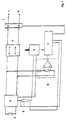
- the residual current is measured within the residual current circuit breaker after the secondary winding of its summation current transformer in the event of a residual current. If it exceeds a predetermined limit value and if it does not switch off the main power contacts within a predetermined time, the supply lines L and N are irreversibly cut in an additional device or an additional device.
- the opening of the main current contacts is recognized by a voltage measurement directly behind the main current contacts.
- the supply lines are cut in the additional device either by opening contacts, cutting lines or by destroying the power lines with the help of a miniature explosive charge.
- the power lines N and L run through the device 1 for separating them via the switching mechanism 2 through the summation current transformer 3 to the consumer 4.
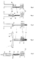
- Figures 2-4 show three electro-mechanical separating means which are suitable for both the phase conductor L and for the neutral conductor N.
- FIG. 4 shows a conductor 15 with a predetermined breaking point 16.
- the insulating body breaks this point as soon as the magnetic core 11 shoots into the coil 13. It is advantageously knife-shaped. If the drive is strong enough, the predetermined breaking point 16 is dispensed with when using an insulated knife 12.
- Fig. 6 shows a plug-in arrangement for separating the lines L and N. The coil 13 pulls the contact pin 10 out of the contact sleeve 9 with the aid of the magnetic core 11.
- FIG. 7 shows a plug contact arrangement like FIG.
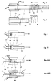
- FIGS. 9 and 10 show a further drive system for the separation of the mains supply lines L and N.
- 17 represents a cartridge-like structure which is filled with an explosive 18, such as powder.
- the cartridge 17 is closed with a piston 19. If the command to disconnect the lines comes, the powder 18 is ignited via the spark gap 20, the piston 19 then performs all of the drive functions described with reference to FIGS. 2-8, which the magnetic core 11 performs there.
- the constriction 21 prevents the disk-shaped piston 19 from emerging from the cartridge 17.
- FIGS. 11 and 12 show a further possibility of pyrotechnic separation of the supply lines.
- On an isolated, for example spherical Capsule 23 is an electrically conductive, self-contained tape 24, which is preferably made of copper, applied.
- the power supply lines that need to be disconnected in the event of a fault are attached to the tape 24 at opposite points 25 and 26.
- In the interior of the capsule there is powder 18 analogously to FIGS. 9 and 10. In the event of a fault, this is ignited analogously to FIGS. 9 and 10 by means of the spark gap 20.
- FIG. 13 shows a separating device similar to FIGS. 11 and 12.
- Two cartridge-like structures 27 and 28 or cartridge-like and piston-like are inserted into one another in an electrically conductive manner and filled with powder 18.
- the powder 18 is located in an insulating capsule 29, into which the ignition lines 30, electrically insulated, lead to the spark gap 20. After ignition, the capsule bursts, the explosion pressure pushes the two structures 27 and 28 apart and thereby reliably separates the mains leads connected to them.
Landscapes
- Engineering & Computer Science (AREA)
- Power Engineering (AREA)
- Breakers (AREA)
Applications Claiming Priority (2)
| Application Number | Priority Date | Filing Date | Title |
|---|---|---|---|
| DE19528918 | 1995-08-07 | ||
| DE1995128918 DE19528918A1 (de) | 1995-08-07 | 1995-08-07 | Fehlerstromschutzschalter mit Notaus-Zusatzschaltgerät |
Publications (1)
| Publication Number | Publication Date |
|---|---|
| EP0788209A1 true EP0788209A1 (fr) | 1997-08-06 |
Family
ID=7768854
Family Applications (1)
| Application Number | Title | Priority Date | Filing Date |
|---|---|---|---|
| EP96112582A Ceased EP0788209A1 (fr) | 1995-08-07 | 1996-08-03 | Disjoncteur à courant de défaut avec interrupteur d'arrêt d'urgence auxiliaire |
Country Status (2)
| Country | Link |
|---|---|
| EP (1) | EP0788209A1 (fr) |
| DE (1) | DE19528918A1 (fr) |
Cited By (3)
| Publication number | Priority date | Publication date | Assignee | Title |
|---|---|---|---|---|
| WO2007123389A1 (fr) * | 2006-04-26 | 2007-11-01 | See Ni Fong | Dispositif de sécurité contre fuite à la terre à alarme temporisée |
| CN108896906A (zh) * | 2018-05-04 | 2018-11-27 | 宁波新胜中压电器有限公司 | 一二次融合开关动作特性测试仪及测试方法 |
| EP4016577A1 (fr) * | 2020-11-26 | 2022-06-22 | Siemens Mobility GmbH | Dispositif électrique intermédiaire, en particulier pour un véhicule ferroviaire |
Families Citing this family (2)
| Publication number | Priority date | Publication date | Assignee | Title |
|---|---|---|---|---|
| DE19735416A1 (de) * | 1997-08-14 | 1999-02-18 | Siemens Ag | Schutzeinrichtung |
| DE19746315A1 (de) * | 1997-10-21 | 1999-05-06 | Abb Patent Gmbh | Einrichtung zum Prüfen eines Fehlerstromschutzschalters |
Citations (8)
| Publication number | Priority date | Publication date | Assignee | Title |
|---|---|---|---|---|
| US3003045A (en) * | 1958-09-08 | 1961-10-03 | Clyde L Tichenor | Electrical switching device |
| DE1904244A1 (de) * | 1968-01-20 | 1970-08-06 | Fuji Electric Co Ltd | Explosionsschalter |
| DE2425212A1 (de) * | 1974-05-24 | 1975-12-04 | Lauerer Friedrich | Redundanz-fehlerstromschutzschalter |
| EP0144660A1 (fr) * | 1983-10-26 | 1985-06-19 | ROBERT KRUPS STIFTUNG & CO. KG. | Dispositif de connexion électrique, comme une prise femelle, pour un consommateur électrique |
| EP0181006A2 (fr) * | 1984-11-09 | 1986-05-14 | Cuisinarts Corporation | Interrupteur de sûreté |
| US4829390A (en) * | 1986-09-15 | 1989-05-09 | Simon Robert E | Electrical switch and circuitry for appliance |
| EP0513405A1 (fr) * | 1991-05-11 | 1992-11-19 | Intermacom A.G. | Méthode et dispositif d'interruption de courant pour appareils et équipements actionnés électriquement |
| EP0563947A1 (fr) * | 1992-04-03 | 1993-10-06 | Dynamit Nobel Aktiengesellschaft | Méthode de protection de circuits, en particulier de circuits à courants forts, contre les surintensité et élément de protection électrique, en particulier pour courants forts |
-
1995
- 1995-08-07 DE DE1995128918 patent/DE19528918A1/de not_active Withdrawn
-
1996
- 1996-08-03 EP EP96112582A patent/EP0788209A1/fr not_active Ceased
Patent Citations (8)
| Publication number | Priority date | Publication date | Assignee | Title |
|---|---|---|---|---|
| US3003045A (en) * | 1958-09-08 | 1961-10-03 | Clyde L Tichenor | Electrical switching device |
| DE1904244A1 (de) * | 1968-01-20 | 1970-08-06 | Fuji Electric Co Ltd | Explosionsschalter |
| DE2425212A1 (de) * | 1974-05-24 | 1975-12-04 | Lauerer Friedrich | Redundanz-fehlerstromschutzschalter |
| EP0144660A1 (fr) * | 1983-10-26 | 1985-06-19 | ROBERT KRUPS STIFTUNG & CO. KG. | Dispositif de connexion électrique, comme une prise femelle, pour un consommateur électrique |
| EP0181006A2 (fr) * | 1984-11-09 | 1986-05-14 | Cuisinarts Corporation | Interrupteur de sûreté |
| US4829390A (en) * | 1986-09-15 | 1989-05-09 | Simon Robert E | Electrical switch and circuitry for appliance |
| EP0513405A1 (fr) * | 1991-05-11 | 1992-11-19 | Intermacom A.G. | Méthode et dispositif d'interruption de courant pour appareils et équipements actionnés électriquement |
| EP0563947A1 (fr) * | 1992-04-03 | 1993-10-06 | Dynamit Nobel Aktiengesellschaft | Méthode de protection de circuits, en particulier de circuits à courants forts, contre les surintensité et élément de protection électrique, en particulier pour courants forts |
Cited By (4)
| Publication number | Priority date | Publication date | Assignee | Title |
|---|---|---|---|---|
| WO2007123389A1 (fr) * | 2006-04-26 | 2007-11-01 | See Ni Fong | Dispositif de sécurité contre fuite à la terre à alarme temporisée |
| CN108896906A (zh) * | 2018-05-04 | 2018-11-27 | 宁波新胜中压电器有限公司 | 一二次融合开关动作特性测试仪及测试方法 |
| CN108896906B (zh) * | 2018-05-04 | 2020-09-11 | 宁波新胜中压电器有限公司 | 一二次融合开关动作特性测试仪及测试方法 |
| EP4016577A1 (fr) * | 2020-11-26 | 2022-06-22 | Siemens Mobility GmbH | Dispositif électrique intermédiaire, en particulier pour un véhicule ferroviaire |
Also Published As
| Publication number | Publication date |
|---|---|
| DE19528918A1 (de) | 1997-02-13 |
Similar Documents
| Publication | Publication Date | Title |
|---|---|---|
| DE102020125293A1 (de) | Kontaktschwebeauslösemechanismen zur verwendung mit schaltvorrichtungen, die pyrotechnische merkmale umfassen | |
| EP0777928B1 (fr) | Disjoncteur a courant de defaut pourvu d'un dispositif de surveillance automatique | |
| EP0495771B1 (fr) | Disjoncteur différentiel | |
| EP0350477A2 (fr) | Dispositif de débranchement pour dérivateurs de surtension | |
| DE69711277T2 (de) | Schutzvorrichtung gegen die Folgen von internen Fehlern in einem elektrischen Gerät | |
| EP3622548B1 (fr) | Disjoncteur pyrotechnique et réseau d'alimentation équipé d'un disjoncteur pyrotechnique | |
| WO1986006222A1 (fr) | Disjoncteur pour courants de defaut | |
| DE3029453C2 (de) | Geräteanordnung zum Netzanschluß | |
| AT405777B (de) | Abtrennvorrichtung für überspannungsableiter | |
| DE19528918A1 (de) | Fehlerstromschutzschalter mit Notaus-Zusatzschaltgerät | |
| DE1763552A1 (de) | Stromunterbrecher mit einer Anordnung zur Schnellwiedereinschaltung | |
| DE2657738A1 (de) | Einrichtung fuer kraftfahrzeuge | |
| EP0083036A1 (fr) | Protection contre le démarrage pour un véhicule électrique | |
| EP0825068A1 (fr) | Dispositif de coupure d'urgence pour réseaux électriques de bord | |
| DE69409356T2 (de) | Prüfeinrichtung für Differentialschutzschalter und diese Vorrichtung enthaltende Differentialschutzschalter | |
| DE2800076C2 (de) | Strombegrenzungsschalter mit elektronischer Steuerschaltung | |
| EP0293376A1 (fr) | Circuit protecteur pour appareils electriques | |
| EP0951046A2 (fr) | Disjoncteur à courant de défaut | |
| DE19523534A1 (de) | Netzspannungsabhängige Fehlerstromschutzeinrichtung | |
| DE4142970A1 (de) | Fehlerstrom- und/oder differenzstromschutzschalter | |
| EP3549150B1 (fr) | Dispositif pour séparer un réseau de bord d'une source d'énergie | |
| EP0676844B1 (fr) | Coupe-circuit auto-surveillant en cas de défaut à la masse | |
| EP0144660A1 (fr) | Dispositif de connexion électrique, comme une prise femelle, pour un consommateur électrique | |
| DE2420465C3 (de) | Elektrischer Leistungsschalter mit einem ersten und einem zweiten Sekundärauslöser | |
| DE19615047A1 (de) | Fehlerstromgeschützte Steckdose |
Legal Events
| Date | Code | Title | Description |
|---|---|---|---|
| PUAI | Public reference made under article 153(3) epc to a published international application that has entered the european phase |
Free format text: ORIGINAL CODE: 0009012 |
|
| AK | Designated contracting states |
Kind code of ref document: A1 Designated state(s): AT BE DE DK ES FR GB IT NL PT SE |
|
| RAP1 | Party data changed (applicant data changed or rights of an application transferred) |
Owner name: AEG NIEDERSPANNUNGSTECHNIK GMBH & CO. KG |
|
| RIN1 | Information on inventor provided before grant (corrected) |
Inventor name: BERTHOLD,RAINER |
|
| 17P | Request for examination filed |
Effective date: 19971209 |
|
| 17Q | First examination report despatched |
Effective date: 19980911 |
|
| GRAG | Despatch of communication of intention to grant |
Free format text: ORIGINAL CODE: EPIDOS AGRA |
|
| STAA | Information on the status of an ep patent application or granted ep patent |
Free format text: STATUS: THE APPLICATION HAS BEEN REFUSED |
|
| 18R | Application refused |
Effective date: 20020329 |