EP0788215A2 - Gebläse-Motor mit einstellbarer Phasensynchronisierung - Google Patents
Gebläse-Motor mit einstellbarer Phasensynchronisierung Download PDFInfo
- Publication number
- EP0788215A2 EP0788215A2 EP97100255A EP97100255A EP0788215A2 EP 0788215 A2 EP0788215 A2 EP 0788215A2 EP 97100255 A EP97100255 A EP 97100255A EP 97100255 A EP97100255 A EP 97100255A EP 0788215 A2 EP0788215 A2 EP 0788215A2
- Authority
- EP
- European Patent Office
- Prior art keywords
- motor
- brushless
- rotor
- stator
- fan
- Prior art date
- Legal status (The legal status is an assumption and is not a legal conclusion. Google has not performed a legal analysis and makes no representation as to the accuracy of the status listed.)
- Granted
Links
- 238000001816 cooling Methods 0.000 claims abstract description 13
- 238000012544 monitoring process Methods 0.000 claims abstract description 5
- 238000007789 sealing Methods 0.000 claims description 26
- 238000000034 method Methods 0.000 claims description 15
- 239000012212 insulator Substances 0.000 claims description 10
- 239000000463 material Substances 0.000 claims description 5
- 239000004642 Polyimide Substances 0.000 claims description 2
- 229920001721 polyimide Polymers 0.000 claims description 2
- 229910001220 stainless steel Inorganic materials 0.000 claims description 2
- 239000010935 stainless steel Substances 0.000 claims description 2
- 238000002955 isolation Methods 0.000 abstract description 2
- 239000007789 gas Substances 0.000 description 33
- 238000013461 design Methods 0.000 description 4
- 238000010586 diagram Methods 0.000 description 4
- 238000012360 testing method Methods 0.000 description 4
- 238000013459 approach Methods 0.000 description 3
- 239000003990 capacitor Substances 0.000 description 3
- 230000001276 controlling effect Effects 0.000 description 3
- 230000003111 delayed effect Effects 0.000 description 3
- 230000009977 dual effect Effects 0.000 description 3
- 230000000670 limiting effect Effects 0.000 description 3
- 230000003068 static effect Effects 0.000 description 3
- PXGOKWXKJXAPGV-UHFFFAOYSA-N Fluorine Chemical compound FF PXGOKWXKJXAPGV-UHFFFAOYSA-N 0.000 description 2
- 230000003247 decreasing effect Effects 0.000 description 2
- 230000000694 effects Effects 0.000 description 2
- 229910052731 fluorine Inorganic materials 0.000 description 2
- 239000011737 fluorine Substances 0.000 description 2
- 229910052736 halogen Inorganic materials 0.000 description 2
- 150000002367 halogens Chemical class 0.000 description 2
- 238000005286 illumination Methods 0.000 description 2
- 238000004519 manufacturing process Methods 0.000 description 2
- 230000003287 optical effect Effects 0.000 description 2
- 230000010355 oscillation Effects 0.000 description 2
- 238000000926 separation method Methods 0.000 description 2
- ZAMOUSCENKQFHK-UHFFFAOYSA-N Chlorine atom Chemical compound [Cl] ZAMOUSCENKQFHK-UHFFFAOYSA-N 0.000 description 1
- RYGMFSIKBFXOCR-UHFFFAOYSA-N Copper Chemical compound [Cu] RYGMFSIKBFXOCR-UHFFFAOYSA-N 0.000 description 1
- 229920004747 ULTEM® 1000 Polymers 0.000 description 1
- XAGFODPZIPBFFR-UHFFFAOYSA-N aluminium Chemical compound [Al] XAGFODPZIPBFFR-UHFFFAOYSA-N 0.000 description 1
- 229910052782 aluminium Inorganic materials 0.000 description 1
- 229910052801 chlorine Inorganic materials 0.000 description 1
- 239000000460 chlorine Substances 0.000 description 1
- 230000006835 compression Effects 0.000 description 1
- 238000007906 compression Methods 0.000 description 1
- 229910052802 copper Inorganic materials 0.000 description 1
- 239000010949 copper Substances 0.000 description 1
- 230000008878 coupling Effects 0.000 description 1
- 238000010168 coupling process Methods 0.000 description 1
- 238000005859 coupling reaction Methods 0.000 description 1
- 238000011161 development Methods 0.000 description 1
- 230000005284 excitation Effects 0.000 description 1
- -1 fluorine (F) Chemical class 0.000 description 1
- 230000017525 heat dissipation Effects 0.000 description 1
- 229910052734 helium Inorganic materials 0.000 description 1
- 239000001307 helium Substances 0.000 description 1
- SWQJXJOGLNCZEY-UHFFFAOYSA-N helium atom Chemical compound [He] SWQJXJOGLNCZEY-UHFFFAOYSA-N 0.000 description 1
- 229910052743 krypton Inorganic materials 0.000 description 1
- DNNSSWSSYDEUBZ-UHFFFAOYSA-N krypton atom Chemical compound [Kr] DNNSSWSSYDEUBZ-UHFFFAOYSA-N 0.000 description 1
- 230000007257 malfunction Effects 0.000 description 1
- 230000007246 mechanism Effects 0.000 description 1
- 239000000203 mixture Substances 0.000 description 1
- 229910052754 neon Inorganic materials 0.000 description 1
- GKAOGPIIYCISHV-UHFFFAOYSA-N neon atom Chemical compound [Ne] GKAOGPIIYCISHV-UHFFFAOYSA-N 0.000 description 1
- 238000000206 photolithography Methods 0.000 description 1
- 238000000746 purification Methods 0.000 description 1
- 238000003908 quality control method Methods 0.000 description 1
- 230000002829 reductive effect Effects 0.000 description 1
- 230000001105 regulatory effect Effects 0.000 description 1
- 230000000284 resting effect Effects 0.000 description 1
- 230000001960 triggered effect Effects 0.000 description 1
- 238000004804 winding Methods 0.000 description 1
Images



Classifications
-
- H—ELECTRICITY
- H02—GENERATION; CONVERSION OR DISTRIBUTION OF ELECTRIC POWER
- H02P—CONTROL OR REGULATION OF ELECTRIC MOTORS, ELECTRIC GENERATORS OR DYNAMO-ELECTRIC CONVERTERS; CONTROLLING TRANSFORMERS, REACTORS OR CHOKE COILS
- H02P6/00—Arrangements for controlling synchronous motors or other dynamo-electric motors using electronic commutation dependent on the rotor position; Electronic commutators therefor
- H02P6/06—Arrangements for speed regulation of a single motor wherein the motor speed is measured and compared with a given physical value so as to adjust the motor speed
-
- F—MECHANICAL ENGINEERING; LIGHTING; HEATING; WEAPONS; BLASTING
- F04—POSITIVE - DISPLACEMENT MACHINES FOR LIQUIDS; PUMPS FOR LIQUIDS OR ELASTIC FLUIDS
- F04D—NON-POSITIVE-DISPLACEMENT PUMPS
- F04D27/00—Control, e.g. regulation, of pumps, pumping installations or pumping systems specially adapted for elastic fluids
- F04D27/004—Control, e.g. regulation, of pumps, pumping installations or pumping systems specially adapted for elastic fluids by varying driving speed
-
- H—ELECTRICITY
- H01—ELECTRIC ELEMENTS
- H01S—DEVICES USING THE PROCESS OF LIGHT AMPLIFICATION BY STIMULATED EMISSION OF RADIATION [LASER] TO AMPLIFY OR GENERATE LIGHT; DEVICES USING STIMULATED EMISSION OF ELECTROMAGNETIC RADIATION IN WAVE RANGES OTHER THAN OPTICAL
- H01S3/00—Lasers, i.e. devices using stimulated emission of electromagnetic radiation in the infrared, visible or ultraviolet wave range
- H01S3/02—Constructional details
- H01S3/03—Constructional details of gas laser discharge tubes
- H01S3/036—Means for obtaining or maintaining the desired gas pressure within the tube, e.g. by gettering, replenishing; Means for circulating the gas, e.g. for equalising the pressure within the tube
-
- H—ELECTRICITY
- H02—GENERATION; CONVERSION OR DISTRIBUTION OF ELECTRIC POWER
- H02K—DYNAMO-ELECTRIC MACHINES
- H02K29/00—Motors or generators having non-mechanical commutating devices, e.g. discharge tubes or semiconductor devices
- H02K29/06—Motors or generators having non-mechanical commutating devices, e.g. discharge tubes or semiconductor devices with position sensing devices
- H02K29/08—Motors or generators having non-mechanical commutating devices, e.g. discharge tubes or semiconductor devices with position sensing devices using magnetic effect devices, e.g. Hall-plates, magneto-resistors
-
- F—MECHANICAL ENGINEERING; LIGHTING; HEATING; WEAPONS; BLASTING
- F05—INDEXING SCHEMES RELATING TO ENGINES OR PUMPS IN VARIOUS SUBCLASSES OF CLASSES F01-F04
- F05D—INDEXING SCHEME FOR ASPECTS RELATING TO NON-POSITIVE-DISPLACEMENT MACHINES OR ENGINES, GAS-TURBINES OR JET-PROPULSION PLANTS
- F05D2270/00—Control
- F05D2270/30—Control parameters, e.g. input parameters
- F05D2270/335—Output power or torque
-
- Y—GENERAL TAGGING OF NEW TECHNOLOGICAL DEVELOPMENTS; GENERAL TAGGING OF CROSS-SECTIONAL TECHNOLOGIES SPANNING OVER SEVERAL SECTIONS OF THE IPC; TECHNICAL SUBJECTS COVERED BY FORMER USPC CROSS-REFERENCE ART COLLECTIONS [XRACs] AND DIGESTS
- Y02—TECHNOLOGIES OR APPLICATIONS FOR MITIGATION OR ADAPTATION AGAINST CLIMATE CHANGE
- Y02B—CLIMATE CHANGE MITIGATION TECHNOLOGIES RELATED TO BUILDINGS, e.g. HOUSING, HOUSE APPLIANCES OR RELATED END-USER APPLICATIONS
- Y02B30/00—Energy efficient heating, ventilation or air conditioning [HVAC]
- Y02B30/70—Efficient control or regulation technologies, e.g. for control of refrigerant flow, motor or heating
Definitions
- the present invention relates generally to brushless DC motors and, more particularly, to a brushless DC motor driven blower-type axial fan used for the circulation of a gas within a laser cavity.
- Excimer lasers generally operate in a pulsed mode. Pulsing is required to provide the gas within the discharge region sufficient time to return to the ground or initial thermal state. In a static gas system, the gas may take times on the order of a second to reach this state, thus severely limiting the repetition rate. Modern laser systems achieve higher repetition rates by actively circulating the gas within the gas discharge region, typically using a tangential blower fan to circulate the gas.
- high gas flow rates and therefore high blower fan speeds are required. Since doubling the speed of the blower fan results in an eight fold increase in the input power to the motor, high blower fan speeds generally result in increased motor and motor coupling complexity and decreased motor life. The primary factor responsible for lowering the motor's life expectancy is the increased operational heat of the motor.
- the present invention provides a brushless DC motor with an adjustable timing feature.
- the timing adjustment allows a specific motor's performance to be optimized by compensating for individual variations in the operating characteristics of the rotor position sensors and/or in their locations.
- the end cap of the stator housing contains three rotor position sensors.
- the end cap can be rotated about the central axis of the rotor, thereby altering the position of the sensors with respect to the stator. Once the location of the sensors has been optimized, the position of the assembly with respect to the stator housing can be fixed.
- the rotor position sensors are affixed to a heat sink within a portion of the motor housing.
- the cooling can either be active or passive. Active cooling techniques include the use of thermoelectric coolers. Passive cooling techniques include increasing the cooling area of the assembly, preferably through the use of cooling fins.
- a structure enclosing the rotor position sensors is used to improve the thermal and electrical isolation of the sensors.
- two brushless DC motors are coupled to a single drive shaft.
- a single command signal is simultaneously sent to both motors, the command signal controlling the drive current applied to the motors.
- the division of the load between the motors is approximately equal.
- the command signal is automatically varied in order to obtain a desired drive shaft speed.
- the drive shaft speed is continually monitored and compared to a preset maximum limit. If the drive shaft speed equals or exceeds the preset limit the motors are temporarily disabled.
- FIG. 1 is an illustration of a compact excimer laser in which a brushless DC motor is used to power a fan which circulates gas within the laser cavity.
- a brushless DC motor is used to power a fan which circulates gas within the laser cavity.
- Fig. 1 is an end view of an excimer laser of a particular design.
- Laser cavity 100 is formed from two housing halves, 101 and 103. Housing halves 101 and 103 are sealed with an O-ring 105 of fluorine and/or chlorine resistant material.
- Within cavity 100 is a cathode 107 and an anode 109.
- an electric discharge is formed within area 111 across a mixture of gases, generally consisting of a rare gas such as krypton (Kr), a halogen such as fluorine (F), and a buffer gas such as helium (He) or neon (Ne).
- the pulse rate is typically quite low. If the gas is static, the gas volume within the discharge area must be given sufficient time to return to its initial thermal state between laser pulses. Generally this return time is on the order of one second, thus limiting the pulse rate in a static gas system to approximately 1 pulse per second. If the gas is circulated the pulse rate can be increased.
- the repetition rate at which the laser can be discharged depends upon the circulation velocity and the rate at which the gas volume within the discharge volume is exchanged. Thus, the higher the circulation velocity, the higher the achievable repetition rate.
- gas is circulated throughout cavity 100 following gas flow lines 119.
- a fan 121 comprised of a plurality of fan blades 123 extending parallel to a fan axis 125, force the circulation of the gas along flow lines 119.
- the circulating gas is cooled using a heat exchanger 127.
- the directional flow of gas is controlled using one or more control vanes 129.
- a portion of the circulating gas can be siphoned off for purification with a filter (not shown), thus extending the life of the gas contained within cavity 100.
- Fig. 1 is preferably mounted outside of cavity 100.
- Fig. 2 is an illustration of a prior art approach to mounting an exterior DC brushless motor 200 to drive fan 121.
- Fan 121 is coupled to a drive shaft 201.
- a rotor 203 At the end of drive shaft 201 is a rotor 203.
- Shaft 201 passes through a bearing structure 205 mounted into the cavity wall 103.
- a stator 207 Surrounding rotor 203 is a stator 207 comprised of a series of windings.
- a sealing assembly 209 In order to prevent the corrosive gases within cavity 100 from passing through bearing structure 205 and into the stator assembly 207, a sealing assembly 209 completely encompasses rotor 203.
- Sealing assembly 209 is constructed of a corrosive resistant material such as stainless steel and is sealed to cavity wall 103 with a corrosive resistant O-ring 211.
- rotor position sensor 213 mounted next to sealing assembly 209 and in close proximity to rotor 203 is at least one rotor position sensor 213, such as a Hall sensor.
- Hall sensors are sensitive to magnetic fields, generating an output voltage which is proportional to the strength of the magnetic field.
- Hall sensors as described herein for use in the present invention, are commercially available from companies such as Honeywell®. The operation of such sensors is well known by those of skill in the art.
- Hall sensor 213 is able to detect the rotational position of the magnets within rotor 203, the output signal of this detector being fed back to a circuit board 215.
- Circuit board 215 directs the power from a power input connector 217 to the stator 207.
- the motor assembly is held in place with a stator housing 219 and an end plate 221.
- Fig. 3 is an illustration of a DC brushless motor according to the present invention. Due to the improved heat dissipation and protection offered by this configuration, the motor and associated electronics are capable of sustaining speeds greater than 4000 RPM in one embodiment.
- this system has the primary components of a drive shaft 301, a rotor 303, a shaft bearing 305, a stator 307, a sealing element 309, Hall sensors 311, a circuit board 313, and a stator housing 315.
- Hall sensors 311 are mounted directly onto circuit board 313, circuit board 313 being mounted to a heat sink portion 317 of end cap 319.
- end cap 319 and associated heat sink portion 317 are constructed of a material with high thermal conductivity such as copper or aluminum, thus efficiently drawing heat away from circuit board 313 and its integral sensors 311.
- Circuit board 313 and sensors 311 are mounted to portion 317 using well known techniques for maximizing thermal contact while avoiding electrical shorts.
- the preferred embodiment of the invention includes an insulator cap 321.
- Insulator cap 321 fits over a section of portion 317, thereby enclosing both the circuit board and the sensors.
- insulator cap 321 is constructed of a polyimide material, such as Ultem® 1000 resin, having good electrical insulating properties as well as good thermal insulating properties. Therefore in this embodiment cap 321 not only reduces the amount of heat absorbed by board 313 and sensors 311, but also limits the possibility of shorting out circuit board 313.
- Fig. 4 is an exploded view of the preferred embodiment. This view clearly shows circuit board 313 and Hall sensors 311. In this embodiment there are three Hall sensors, thus uniquely defining the location of the rotor. Board 313 is mounted to heat sink portion 317 with bolts 401. Insulating cap 321 fits over portion 317, resting on lip 403, and is held in place with bolts 405.
- cap 319 In order to maximize the cooling capacity of end cap 319 and its associated heat sink 317, a section 407 of cap 319 is finned. The fins increase the surface area of cap 319, thereby increasing the possible heat flow through surrounding air. If further cooling is required cap 319 can be actively cooled, for example with thermoelectric coolers (not shown), or forced convection.
- the position of the rotor is determined using non-contacting sensors, preferably at least three Hall sensors. This positional information is important in order to properly time the application of power to the stator, thereby maximizing the efficiency of the motor. However, in order to achieve optimal motor performance the system must be calibrated.
- the effects of the performance variations of the Hall sensors are exacerbated by the mounting location of the sensors for particular applications.
- the motor used to drive a blower fan in an excimer laser system is often mounted outside of the laser cavity.
- a sealing element is interposed between the rotor and the stator as illustrated in Figs. 2-3.
- the sealing element increases the separation distance between sensors 311 and rotor 303 thereby decreasing the magnetic field strength at the location of the sensors.
- the separation distance is further increased due to insulating cup 321.
- the magnetic field strength is also reduced due to the placement of the sensors at the end of the rotor.
- mounting variations in sensors 311 and circuit board 313 may also lead to varying performance characteristics.
- sensors 311 are rigidly attached to circuit board 313 which is, in turn, rigidly attached to end cap 319.
- stator 307 is held rigid with respect to exterior wall 103. In this embodiment stator 307 is fixedly attached to stator housing 315. Housing 315 fits over the flange of sealing element 309. A slot 409 at the edge of housing 315 fits over a pin (not shown) in the flange of element 309.
- end cap 319 and stator 307/stator housing 315 are fixed to the laser cavity by a single assembly bolt 411 and a compression spring 413.
- Bolt 411 passes through the center of end cap 319 and is threaded into an end portion of sealing element 309.
- Element 309 is attached to cavity exterior wall 103 by eight bolts (not shown).
- End cap 319 contains three slots 415 which permit it to rotate around the center axis of the motor assembly, thereby allowing the timing of the motor to be varied. Passing through each slot 415 is a bolt 417, these bolts threaded into housing 315.
- bolts 411 and 417 In order to adjust the timing of the motor, bolts 411 and 417 must be sufficiently loosened to allow cap 319 to rotate with respect to stator housing 315.
- the length of slots 415 determine the degree of rotation permitted.
- the outside edge of end cap 319 contains a null indicator marking 419.
- the permitted degree of rotation on either side of null marking 419 is within about 10 degrees.
- Fig. 6 is an illustration of an assembled motor which is ready for mounting.
- a timing slot 415/bolt 417 combination is clearly visible as are timing marks 419 and 421.
- the end portion of cap 319 contains cooling fins 407.
- Fig. 7 is a flow diagram of the procedure used to time the preferred embodiment of the invention.
- the first step is to apply an appropriate load to the motor assembly (Step 701).
- This load should equal the expected load.
- the load can either be the actual load, for example that resulting from operating an excimer laser such as that shown in Fig. 1, or the load can be simulated.
- the motor assembly shown in Figs. 3-5 is ideally suited to the use of simulated loads for several reasons. First, the stator, stator housing, end cap, and all associated electronics and sensors are contained in a single assembly. Second, due to the 'non-contact' design of this motor, the outer motor assembly can easily be affixed to a testing assembly.
- the testing assembly simply requires a rotor and sealing element identical to that used in the actual motor assembly onto which the outer assembly can be attached.
- the timing of the motor is relatively independent of the rotor, thus allowing the outer motor assembly to be timed and used with any rotor/sealing element combination under the same load conditions.
- a Magtrol Dynamometer Model HD-710 operating under the appropriate speed and load conditions is used to simulate the load.
- Step 703 the motor must warm up to its normal operating temperature (Step 703) to allow for the shift in the operate/release characteristics of the sensors as previously described.
- an operating temperature of 70 °C, measured on the stator housing is considered normal operating temperature.
- the timing of the motor is then adjusted (Step 709) by minimizing the power input (Step 711). When the minimum stator power input is obtained, the timing procedure is complete (Step 713).
- the timing adjustment is made by loosening bolts 417, rotating end cap 319 with respect to stator housing 315, and retightening bolts 417 to allow further testing. Positioning of alignment marks 419 and 421 is then recorded for production quality control purposes.
- Fig. 8 is an illustration of an embodiment of the invention in which two brushless DC motors are used to power a single blower fan within an excimer laser cavity.
- drive shaft 301 of fan 121 is directly coupled at either end to a rotor 303 within a stator housing 315/end cap 319 assembly. Since both motors are directly coupled to the same fan shaft, the motor control circuitry is important in order to avoid excessive loading of one or both motors.
- Fig. 9 is a block diagram illustrating the prior art approach to controlling a dual motor driven fan such as that illustrated in Fig. 8.
- a first motor 901 is driven by a motor drive circuit 903 and a second motor 905 is driven by a second motor drive circuit 907.
- Motors 901 and 905 drive a single fan 909.
- the system also contains a controller 911.
- controller 911 monitors the current of both motors 901 and 902 as well as the speed of fan 909.
- the fan speed can be monitored by monitoring the speed of either motor 901 or 905 since both motors are directly coupled to the same fan.
- controller 911 monitors the operating current in motors 901 and 905.
- the operating current of each motor is directly proportional to its operating load. If controller 911 determines that the operating currents of the two motors is unbalanced, speed control signals are sent by controller 911 to either one or both motor drive circuits, 903 and 907. By applying different speed control signals to the motors, the load on the individual motors is varied thus preventing one motor from carrying a greater load than the other motor. Once controller 911 has matched the operating currents of motors 901 and 905 to within the predetermined operating tolerances, the speed of the fan is again checked.
- controller 911 adjusts the speeds of the two motors and then repeats the operation of attempting to match the operating currents of the two motors.
- Fig. 10 illustrates an embodiment of the blower speed control according to the present invention.
- the system has a first motor 1001, a first motor drive circuit 1003, a second motor 1005, a second motor drive circuit 1007, a fan 1009, and a controller 1011.
- controller 1011 monitors the speed of the fan by monitoring the speed of either motor 1001 or 1005. If the speed of the fan is incorrect, controller 1011 sends out a single drive current command, either to increase or decrease the drive current of the motors. Therefore the drive current of both motors is simultaneously changed, thus eliminating the necessity of matching motor loads as in the prior art.
- controller 1011 sends out a single drive current command, the same circuit can be used with either a single blower motor, as in Figs. 3-5, or with a dual motor system, as shown in Fig. 8.
- Fig. 11 illustrates an alternate embodiment of the blower speed control system shown in Fig. 10.
- the two systems are identical except the one shown in Fig. 11 has a blower fan protection circuit 1101 which prevents the motors from being damaged by operating at too high of a speed.
- protection circuit 1101 continually compares the fan speed with a preset maximum limit. If the fan speed exceeds the preset limit, a disable signal is sent to the motor drive circuits which prevents further operation of the motors until the disable signal is removed. In the preferred embodiment, the disable signal is sent for a predetermined period of time, after which the operation of the motors can be reinitiated.
- the protection circuit may also be used with a single motor system.
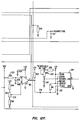
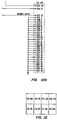
- Fig. 12 is a portion of a laser control circuit which is used to control the blower fan according to the present invention.
- Tachometer input signal seen on connector 1201 (test point 1203), is a TTL level pulse train from the blower controller. The frequency is proportional to the motor speed.
- IC 1205 is a frequency-to-voltage converter which converts pulses at pin 10 to a DC voltage at pin 13. This DC voltage is delayed by the combination of resistor 1207 and capacitor 1209 for almost 1 second to prevent the system from oscillation. The delayed voltage at pin 4 of comparator 1211 is compared with another voltage at pin 5 which is set by potentiometer 1213.
- pin 2 at the output of comparator 1211 goes low and generates an over-speed signal. This signal is sensed by the controller which then shuts the blower off and brings the system down to STANDBY. This output also triggers IC 1215 which is a monostable timer. Pin 3 of this timer is normally low which is inverted to high TTL level by NAND gate 1217.
- pin 3 of the timer goes high for the duration that can be adjusted by potentiometer 1219. In the preferred embodiment this duration is set at 30 seconds.
- pin 3 of the timer goes high, then pin 3 of NAND gate 1217 goes low which causes pin 3 of gate 1221 to go low. This, in turn, will switch pin 8 of gate 1223 to low which turns the blower off for 30 seconds. During this time the computer will not be able to turn the blower on.
- the 30 second off period acts as a watchdog timer that prevents the controller from turning the blower on after an over-speed condition.
- blower speed goes higher, the same changes will happen in the opposite direction, which means pin 6 will go higher and pin 7 will go lower, reducing blower speed ad compensating changes in the system and regulating blower speed. Therefore, although the speed is set by the software, speed control is achieved through hardware.
- analog control voltage from the computer increases, for example due to a malfunction in the system or blower overload, and the speed of the blower does not increase proportionately, then the voltage at pin 5 of 1233 will go higher than pin 6, which will increase the voltage at pin 6 of 1237. This voltage is compared with another voltage which is set by potentiometer 1239.
Landscapes
- Engineering & Computer Science (AREA)
- Electromagnetism (AREA)
- Physics & Mathematics (AREA)
- Power Engineering (AREA)
- Mechanical Engineering (AREA)
- Optics & Photonics (AREA)
- Plasma & Fusion (AREA)
- General Engineering & Computer Science (AREA)
- Control Of Motors That Do Not Use Commutators (AREA)
- Brushless Motors (AREA)
- Structures Of Non-Positive Displacement Pumps (AREA)
- Control Of Positive-Displacement Air Blowers (AREA)
- Lasers (AREA)
Applications Claiming Priority (2)
| Application Number | Priority Date | Filing Date | Title |
|---|---|---|---|
| US59457196A | 1996-01-31 | 1996-01-31 | |
| US594571 | 2000-06-15 |
Publications (3)
| Publication Number | Publication Date |
|---|---|
| EP0788215A2 true EP0788215A2 (de) | 1997-08-06 |
| EP0788215A3 EP0788215A3 (de) | 1997-11-19 |
| EP0788215B1 EP0788215B1 (de) | 2003-04-02 |
Family
ID=24379450
Family Applications (1)
| Application Number | Title | Priority Date | Filing Date |
|---|---|---|---|
| EP97100255A Expired - Lifetime EP0788215B1 (de) | 1996-01-31 | 1997-01-09 | Laser-Gas-Umwälzsystem |
Country Status (6)
| Country | Link |
|---|---|
| US (1) | US5770933A (de) |
| EP (1) | EP0788215B1 (de) |
| JP (1) | JPH09228986A (de) |
| KR (2) | KR100322861B1 (de) |
| CA (1) | CA2190697C (de) |
| DE (1) | DE69720309T2 (de) |
Cited By (4)
| Publication number | Priority date | Publication date | Assignee | Title |
|---|---|---|---|---|
| WO2000007268A1 (en) * | 1998-07-28 | 2000-02-10 | Acculase, Inc. | Improved excimer laser system |
| EP1164667A3 (de) * | 2000-06-08 | 2004-09-29 | Ebara Corporation | Gasentladungslaser |
| EP1670121A1 (de) * | 2004-11-22 | 2006-06-14 | Minebea Co., Ltd. | Elektrische Maschine, insbesondere bürstenloser Gleichstrommotor |
| EP1589641A3 (de) * | 2004-04-22 | 2006-10-04 | Minebea Co., Ltd. | Bürstenloser Gleichstrommotor und Verfahren zum Justieren einer Sensorvorrichtung in einem bürstenlosen Gleichstrommotor |
Families Citing this family (35)
| Publication number | Priority date | Publication date | Assignee | Title |
|---|---|---|---|---|
| US5920164A (en) * | 1996-10-31 | 1999-07-06 | Mfm Technology, Inc. | Brushless linear motor |
| US5848089A (en) * | 1997-07-11 | 1998-12-08 | Cymer, Inc. | Excimer laser with magnetic bearings supporting fan |
| US6757316B2 (en) * | 1999-12-27 | 2004-06-29 | Cymer, Inc. | Four KHz gas discharge laser |
| JP3697036B2 (ja) * | 1997-10-03 | 2005-09-21 | キヤノン株式会社 | 露光装置及びそれを用いた半導体製造方法 |
| JP3169892B2 (ja) * | 1998-04-28 | 2001-05-28 | セイコー精機株式会社 | ターボ分子ポンプ装置 |
| US6144686A (en) * | 1998-08-28 | 2000-11-07 | Cymer, Inc. | Tangential fan with cutoff assembly and vibration control for electric discharge laser |
| US6061376A (en) * | 1998-08-28 | 2000-05-09 | Cymer, Inc. | Tangential fan for excimer laser |
| US6023486A (en) * | 1998-08-28 | 2000-02-08 | Cymer, Inc. | Soldered fan assembly for electric discharge laser |
| JP2000138404A (ja) * | 1998-10-29 | 2000-05-16 | Komatsu Ltd | エキシマレーザ装置用の貫流ファン |
| DE69941930D1 (de) | 1998-11-30 | 2010-03-04 | Ebara Corp | Durch elektrische entladung angeregter excimerlaser |
| JP2000183436A (ja) * | 1998-12-18 | 2000-06-30 | Komatsu Ltd | エキシマレ―ザ装置 |
| JP3766230B2 (ja) * | 1999-04-21 | 2006-04-12 | 株式会社荏原製作所 | エキシマレーザ装置 |
| US6795474B2 (en) * | 2000-11-17 | 2004-09-21 | Cymer, Inc. | Gas discharge laser with improved beam path |
| JP2001050161A (ja) | 1999-08-05 | 2001-02-23 | Ebara Corp | 気体移送機 |
| JP2001111138A (ja) * | 1999-10-04 | 2001-04-20 | Ebara Corp | エキシマレーザ装置 |
| US6765946B2 (en) * | 2000-01-25 | 2004-07-20 | Cymer, Inc. | Fan for gas discharge laser |
| US6847671B1 (en) | 2000-03-29 | 2005-01-25 | Lambda Physik Ag | Blower for gas laser |
| KR20020028668A (ko) * | 2000-10-11 | 2002-04-17 | 밍 루 | 차량의 전동식 조향장치에 사용되는 브러시리스 모터 |
| US6839372B2 (en) * | 2000-11-17 | 2005-01-04 | Cymer, Inc. | Gas discharge ultraviolet laser with enclosed beam path with added oxidizer |
| DE10161945A1 (de) * | 2001-12-17 | 2003-07-17 | W & H Dentalwerk Buermoos Ges | Bürstenloser Elektro-Motor sowie Instrument für eine medizinische Vorrichtung mit einem solchen Motor |
| US20050286599A1 (en) * | 2004-06-29 | 2005-12-29 | Rafac Robert J | Method and apparatus for gas discharge laser output light coherency reduction |
| US8379687B2 (en) | 2005-06-30 | 2013-02-19 | Cymer, Inc. | Gas discharge laser line narrowing module |
| DE102005045283B4 (de) * | 2005-09-22 | 2014-05-15 | Pfeiffer Vacuum Gmbh | Vakuumpumpsystem |
| US7321607B2 (en) * | 2005-11-01 | 2008-01-22 | Cymer, Inc. | External optics and chamber support system |
| US7656114B2 (en) * | 2007-10-03 | 2010-02-02 | Hiwin Mikrosystem Corp. | Servo control apparatus for a linear motor |
| CN101877524B (zh) * | 2009-04-30 | 2013-03-20 | 浙江中科德润科技有限公司 | 一体化轮毂电机 |
| JP5410194B2 (ja) * | 2009-08-07 | 2014-02-05 | 株式会社デンソー | 駆動回路内蔵型モータ |
| US20170005555A1 (en) * | 2015-07-02 | 2017-01-05 | Purdue Research Foundation | Asymmetric salient permanent magnet synchronous machine |
| JP6424921B2 (ja) * | 2017-04-26 | 2018-11-21 | 株式会社明電舎 | ダイナモメータ装置 |
| US11139722B2 (en) * | 2018-03-02 | 2021-10-05 | Black & Decker Inc. | Motor having an external heat sink for a power tool |
| KR102014906B1 (ko) | 2019-07-17 | 2019-08-27 | 임영균 | 샤워 노즐 |
| KR102072511B1 (ko) | 2019-07-17 | 2020-02-03 | 임영균 | 샤워 노즐 |
| KR102055169B1 (ko) | 2019-07-17 | 2019-12-12 | 임영균 | 샤워 노즐 |
| JP2024500674A (ja) * | 2020-12-22 | 2024-01-10 | サイマー リミテッド ライアビリティ カンパニー | ガス放電チャンバブロワのエネルギー消費量を低減すること |
| US20220200401A1 (en) | 2020-12-23 | 2022-06-23 | Black & Decker Inc. | Brushless dc motor with circuit board for winding interconnections |
Citations (1)
| Publication number | Priority date | Publication date | Assignee | Title |
|---|---|---|---|---|
| US4959840A (en) | 1988-01-15 | 1990-09-25 | Cymer Laser Technologies | Compact excimer laser including an electrode mounted in insulating relationship to wall of the laser |
Family Cites Families (14)
| Publication number | Priority date | Publication date | Assignee | Title |
|---|---|---|---|---|
| NL7018060A (de) * | 1970-02-18 | 1971-08-20 | ||
| DE2146893C3 (de) * | 1971-09-20 | 1974-02-07 | Siemens Ag, 1000 Berlin U. 8000 Muenchen | Kollektorloser Gleichstrommotor mit einer durch Hall generatoren gesteuerten, aus Halbleiterschaltelementen aufgebauten Kommutierungseinrichtung |
| US4099143A (en) * | 1977-01-14 | 1978-07-04 | Universal Laser Corp. | Gas recirculating stabilized laser |
| US4086519A (en) * | 1977-02-25 | 1978-04-25 | Electro-Craft Corporation | Hall effect shaft angle position encoder |
| DE3504681A1 (de) * | 1985-02-12 | 1986-09-04 | Deutsche Forschungs- und Versuchsanstalt für Luft- und Raumfahrt e.V., 5000 Köln | Antriebs- und positioniersystem |
| KR880002475B1 (ko) * | 1985-08-21 | 1988-11-14 | 이이수 | 직류 다상 양극성 무정류자 전동기 |
| JPS63240358A (ja) * | 1987-03-25 | 1988-10-06 | Yaskawa Electric Mfg Co Ltd | ブラシレスモ−タのエンコ−ダ調整機構 |
| JPS6455041A (en) * | 1987-08-26 | 1989-03-02 | Tamagawa Seiki Co Ltd | Motor with rotation detector |
| US4891818A (en) * | 1987-08-31 | 1990-01-02 | Acculase, Inc. | Rare gas-halogen excimer laser |
| US5048041A (en) * | 1988-01-15 | 1991-09-10 | Cymer Laser Technologies | Compact excimer laser |
| DE3813064A1 (de) * | 1988-04-19 | 1989-11-02 | Heidolph Elektro Gmbh & Co Kg | Vorrichtung zum justieren des rotorlage-erkennungssystems |
| JPH0749796B2 (ja) * | 1988-09-26 | 1995-05-31 | 三菱電機株式会社 | 密閉形電動圧縮機の保護器 |
| US5377215A (en) * | 1992-11-13 | 1994-12-27 | Cymer Laser Technologies | Excimer laser |
| US5291087A (en) * | 1993-03-03 | 1994-03-01 | Westinghouse Electric Corp. | Sealed electric motor assembly |
-
1996
- 1996-11-19 CA CA002190697A patent/CA2190697C/en not_active Expired - Fee Related
-
1997
- 1997-01-09 EP EP97100255A patent/EP0788215B1/de not_active Expired - Lifetime
- 1997-01-09 DE DE69720309T patent/DE69720309T2/de not_active Expired - Fee Related
- 1997-01-30 KR KR1019970002788A patent/KR100322861B1/ko not_active Expired - Fee Related
- 1997-01-31 JP JP9017966A patent/JPH09228986A/ja active Pending
- 1997-11-13 US US08/969,387 patent/US5770933A/en not_active Expired - Fee Related
-
2001
- 2001-06-22 KR KR1020010035748A patent/KR100343423B1/ko not_active Expired - Fee Related
Patent Citations (1)
| Publication number | Priority date | Publication date | Assignee | Title |
|---|---|---|---|---|
| US4959840A (en) | 1988-01-15 | 1990-09-25 | Cymer Laser Technologies | Compact excimer laser including an electrode mounted in insulating relationship to wall of the laser |
Cited By (4)
| Publication number | Priority date | Publication date | Assignee | Title |
|---|---|---|---|---|
| WO2000007268A1 (en) * | 1998-07-28 | 2000-02-10 | Acculase, Inc. | Improved excimer laser system |
| EP1164667A3 (de) * | 2000-06-08 | 2004-09-29 | Ebara Corporation | Gasentladungslaser |
| EP1589641A3 (de) * | 2004-04-22 | 2006-10-04 | Minebea Co., Ltd. | Bürstenloser Gleichstrommotor und Verfahren zum Justieren einer Sensorvorrichtung in einem bürstenlosen Gleichstrommotor |
| EP1670121A1 (de) * | 2004-11-22 | 2006-06-14 | Minebea Co., Ltd. | Elektrische Maschine, insbesondere bürstenloser Gleichstrommotor |
Also Published As
| Publication number | Publication date |
|---|---|
| KR100322861B1 (ko) | 2002-09-25 |
| US5770933A (en) | 1998-06-23 |
| KR100343423B1 (ko) | 2002-07-12 |
| DE69720309D1 (de) | 2003-05-08 |
| EP0788215B1 (de) | 2003-04-02 |
| KR970060642A (ko) | 1997-08-12 |
| DE69720309T2 (de) | 2004-02-12 |
| EP0788215A3 (de) | 1997-11-19 |
| JPH09228986A (ja) | 1997-09-02 |
| CA2190697C (en) | 2000-07-25 |
| CA2190697A1 (en) | 1997-08-01 |
Similar Documents
| Publication | Publication Date | Title |
|---|---|---|
| US5770933A (en) | Blower motor with adjustable timing | |
| US6509704B1 (en) | Low profile motor | |
| US6504275B2 (en) | Electric motor having rotor-embedded sensor | |
| US5925948A (en) | Axial flow fan motor | |
| US5734241A (en) | Brake control system of a motor | |
| US20030178954A1 (en) | Multiple fault redundant motor | |
| US4378760A (en) | Device for controlling the ventilating means of an internal combustion engine | |
| US20190307017A1 (en) | Motor drive control apparatus, fan, and motor control method | |
| JP2004522040A (ja) | ターボ分子ポンプ | |
| CA2168162C (en) | A switched reluctance motor providing rotor position detection at low speeds without a seperate rotor shaft position sensor | |
| JP2003087966A (ja) | 発電機の保護装置 | |
| US20020003409A1 (en) | Apparatus for motor synchronization | |
| US6819017B2 (en) | Method and apparatus for fan redundancy | |
| US5898296A (en) | Isolation regulator | |
| US5940576A (en) | Electronic control unit for a vacuum pump | |
| JPH11155257A (ja) | インバータユニット付きモータ | |
| KR100330089B1 (ko) | 반도체검사장치의냉각방식 | |
| JPH1137097A (ja) | 冷却ファン付き電動機の冷却ファン駆動制御方法及び装置 | |
| JP2598263Y2 (ja) | 車両のための電気的な機械 | |
| US7023219B2 (en) | A/C generator rotor test apparatus | |
| JPS63173969A (ja) | フアンの回転方向検出方式 | |
| JP3276967B2 (ja) | 回転陽極x線管制御装置 | |
| JPH11101546A (ja) | 冷蔵庫の異常検出装置 | |
| JPH08192376A (ja) | 電動工具 | |
| JP3540574B2 (ja) | 冷蔵庫の異常検出装置 |
Legal Events
| Date | Code | Title | Description |
|---|---|---|---|
| PUAI | Public reference made under article 153(3) epc to a published international application that has entered the european phase |
Free format text: ORIGINAL CODE: 0009012 |
|
| AK | Designated contracting states |
Kind code of ref document: A2 Designated state(s): DE NL |
|
| PUAL | Search report despatched |
Free format text: ORIGINAL CODE: 0009013 |
|
| AK | Designated contracting states |
Kind code of ref document: A3 Designated state(s): DE NL |
|
| 17P | Request for examination filed |
Effective date: 19980515 |
|
| 17Q | First examination report despatched |
Effective date: 20000811 |
|
| RTI1 | Title (correction) |
Free format text: LASER GAS CIRCULATING SYSTEM |
|
| GRAH | Despatch of communication of intention to grant a patent |
Free format text: ORIGINAL CODE: EPIDOS IGRA |
|
| GRAH | Despatch of communication of intention to grant a patent |
Free format text: ORIGINAL CODE: EPIDOS IGRA |
|
| GRAA | (expected) grant |
Free format text: ORIGINAL CODE: 0009210 |
|
| AK | Designated contracting states |
Designated state(s): DE NL |
|
| REF | Corresponds to: |
Ref document number: 69720309 Country of ref document: DE Date of ref document: 20030508 Kind code of ref document: P |
|
| PGFP | Annual fee paid to national office [announced via postgrant information from national office to epo] |
Ref country code: NL Payment date: 20031216 Year of fee payment: 8 |
|
| PLBE | No opposition filed within time limit |
Free format text: ORIGINAL CODE: 0009261 |
|
| STAA | Information on the status of an ep patent application or granted ep patent |
Free format text: STATUS: NO OPPOSITION FILED WITHIN TIME LIMIT |
|
| PGFP | Annual fee paid to national office [announced via postgrant information from national office to epo] |
Ref country code: DE Payment date: 20040301 Year of fee payment: 8 |
|
| 26N | No opposition filed |
Effective date: 20040105 |
|
| PG25 | Lapsed in a contracting state [announced via postgrant information from national office to epo] |
Ref country code: NL Free format text: LAPSE BECAUSE OF NON-PAYMENT OF DUE FEES Effective date: 20050801 |
|
| PG25 | Lapsed in a contracting state [announced via postgrant information from national office to epo] |
Ref country code: DE Free format text: LAPSE BECAUSE OF NON-PAYMENT OF DUE FEES Effective date: 20050802 |
|
| NLV4 | Nl: lapsed or anulled due to non-payment of the annual fee |
Effective date: 20050801 |