EP0788242A1 - Radio-récepteur et méthode de mise en oeuvre - Google Patents
Radio-récepteur et méthode de mise en oeuvre Download PDFInfo
- Publication number
- EP0788242A1 EP0788242A1 EP96309028A EP96309028A EP0788242A1 EP 0788242 A1 EP0788242 A1 EP 0788242A1 EP 96309028 A EP96309028 A EP 96309028A EP 96309028 A EP96309028 A EP 96309028A EP 0788242 A1 EP0788242 A1 EP 0788242A1
- Authority
- EP
- European Patent Office
- Prior art keywords
- synchronisation
- burst
- field
- radio receiver
- quality
- Prior art date
- Legal status (The legal status is an assumption and is not a legal conclusion. Google has not performed a legal analysis and makes no representation as to the accuracy of the status listed.)
- Granted
Links
- 238000000034 method Methods 0.000 title claims description 10
- 238000001514 detection method Methods 0.000 claims description 10
- 238000004891 communication Methods 0.000 claims description 9
- 238000012545 processing Methods 0.000 claims description 5
- 230000001419 dependent effect Effects 0.000 claims 1
- 230000007704 transition Effects 0.000 description 30
- 238000011084 recovery Methods 0.000 description 24
- 230000005540 biological transmission Effects 0.000 description 6
- 230000006866 deterioration Effects 0.000 description 5
- 230000008859 change Effects 0.000 description 2
- 230000011664 signaling Effects 0.000 description 2
- AZFKQCNGMSSWDS-UHFFFAOYSA-N MCPA-thioethyl Chemical compound CCSC(=O)COC1=CC=C(Cl)C=C1C AZFKQCNGMSSWDS-UHFFFAOYSA-N 0.000 description 1
- 230000008901 benefit Effects 0.000 description 1
- 230000001413 cellular effect Effects 0.000 description 1
- 125000004122 cyclic group Chemical group 0.000 description 1
- 230000003628 erosive effect Effects 0.000 description 1
- 230000006872 improvement Effects 0.000 description 1
- 239000004973 liquid crystal related substance Substances 0.000 description 1
- 238000012986 modification Methods 0.000 description 1
- 230000004048 modification Effects 0.000 description 1
- 230000008569 process Effects 0.000 description 1
- 238000012546 transfer Methods 0.000 description 1
Images





Classifications
-
- H—ELECTRICITY
- H04—ELECTRIC COMMUNICATION TECHNIQUE
- H04L—TRANSMISSION OF DIGITAL INFORMATION, e.g. TELEGRAPHIC COMMUNICATION
- H04L7/00—Arrangements for synchronising receiver with transmitter
- H04L7/04—Speed or phase control by synchronisation signals
- H04L7/041—Speed or phase control by synchronisation signals using special codes as synchronising signal
- H04L7/046—Speed or phase control by synchronisation signals using special codes as synchronising signal using a dotting sequence
-
- H—ELECTRICITY
- H04—ELECTRIC COMMUNICATION TECHNIQUE
- H04L—TRANSMISSION OF DIGITAL INFORMATION, e.g. TELEGRAPHIC COMMUNICATION
- H04L1/00—Arrangements for detecting or preventing errors in the information received
- H04L1/20—Arrangements for detecting or preventing errors in the information received using signal quality detector
-
- H—ELECTRICITY
- H04—ELECTRIC COMMUNICATION TECHNIQUE
- H04L—TRANSMISSION OF DIGITAL INFORMATION, e.g. TELEGRAPHIC COMMUNICATION
- H04L7/00—Arrangements for synchronising receiver with transmitter
- H04L7/04—Speed or phase control by synchronisation signals
- H04L7/08—Speed or phase control by synchronisation signals the synchronisation signals recurring cyclically
-
- H—ELECTRICITY
- H04—ELECTRIC COMMUNICATION TECHNIQUE
- H04L—TRANSMISSION OF DIGITAL INFORMATION, e.g. TELEGRAPHIC COMMUNICATION
- H04L1/00—Arrangements for detecting or preventing errors in the information received
- H04L1/004—Arrangements for detecting or preventing errors in the information received by using forward error control
- H04L1/0056—Systems characterized by the type of code used
- H04L1/0061—Error detection codes
-
- H—ELECTRICITY
- H04—ELECTRIC COMMUNICATION TECHNIQUE
- H04L—TRANSMISSION OF DIGITAL INFORMATION, e.g. TELEGRAPHIC COMMUNICATION
- H04L7/00—Arrangements for synchronising receiver with transmitter
- H04L7/0079—Receiver details
- H04L7/0083—Receiver details taking measures against momentary loss of synchronisation, e.g. inhibiting the synchronisation, using idle words or using redundant clocks
Definitions
- This invention relates to radio receivers, and particularly but not exclusively to such receivers forming part of the transceiver of a portable radio telephone or handset, for communication with a base station in a radio telephone system.
- the invention also relates to a method of operation of such radio receivers.
- the invention also relates, particularly but not exclusively, to handsets for communication with base stations in a digital cellular radio telephone system employing transmission by a plurality of carrier frequencies in frames, such as TDMA frames, each consisting of a predetermined number of time slots.
- Any radio system in which information is transmitted in bursts causes problems for the receiving station in maintaining synchronicity with the signals received.
- Many protocols provide for a solution to this problem by including a synchronisation field at the start of a burst to allow the receiving station to synchronise with the signal before signals carrying data or other information are received.
- a synchronisation field comprising a known string of bits is provided at the beginning of each burst so that the receiving station can correlate its timing to that of the incoming signal.
- the known string allows bit synchronisation to be achieved relatively quickly in good conditions ie when the signal is of a high quality.
- the bit synchronisation field must, however, be long enough for bit synchronisation to be achieved under all the circumstances in which the signal quality is suitable to provide information.
- bit synchronisation string is typically a slot synchronisation string that allows the receiving station to locate a particular point in the burst so that the category or type of information carried by the subsequently received bits of that burst can be identified by virtue of their position within the burst.
- Signaling protocols typically provide for error detection so that good data received can be distinguished from corrupt data.
- the quality of a channel for receiving signals can be monitored to determine if a new channel is necessary in order to preserve transfer of the information carried by the signal bursts from the base station to the handset or vice versa. It is desirable to monitor channel quality to allow a better quality channel to be used before too much information is lost.
- the quality of a received signal can be used as a trigger for changing channel.
- a radio receiver for communication in a radio system in which information is transmitted in bursts, a burst having a field for enabling the radio receiver to synchronise with an incoming signal, the radio receiver comprising processing means operable to utilise the interval for the achievement of synchronisation as a measure of signal quality.
- a synchronisation field is typically long enough to enable synchronisation to be achieved when signal quality is less than perfect, there is some redundancy built into the signal ie it is longer than necessary for synchronisation under good conditions. This provides scope for the receiver to use information on the interval for achieving synchronisation to provide information on signal quality.
- This information can be used instead of, or as well as, other signal quality information that can be obtained.
- the advantage of using the synchronisation field to measure signal quality is that a decision to change channels may be made before any data is lost.
- the synchronisation field is particularly useful in detecting sliding collisions that may cause the loss of information at the front end of a data burst.
- Sliding collisions can arise when systems having overlapping spheres of influence operate under the same protocol. This is because a burst in a time slot on one system may occur at a similar time as a burst in a time slot of another system.
- the timing of one system will inevitably drift relative to the other, causing the interference pattern to differ with time.
- a pair of bearer channels utilised on respective systems can, therefore, ' slide ' in and out of interference with one another over a period of time. This type of interference is known as a ' sliding collision ' .
- a method for providing a measure of signal quality in a radio telephone system in which information is transmitted in bursts, a burst having a synchronisation field for enabling synchronisation with an incoming signal, the method comprising utilising the interval for achievement of synchronisation as a measure of signal quality.
- the radio telephone system conforms to the DECT (Digital European Cordless Telecommunications) standard and uses ten carrier frequencies, separated by 1.728 MHz, within a frequency band from 1880 MHz to 1900 MHz.
- This system divides time into TDMA frames, with each frame having a time duration of 10ms.
- Each frame is divided into 24 time slots, numbered from 0 to 23.
- Each frame is divided into two halves, the first half (slots 0 to 11) being reserved for the transmission of the base station and the second half (slots 12 to 23) being reserved for the transmission of the handset.
- a DECT system typically includes one or more fixed parts and several radio fixed parts or base stations 1, 2 supporting respective cells 3, 4. Many portable parts or handsets 5 can use each cell.
- Each fixed part is physically connected to a standard wireline telephone system, each radio fixed part 1, 2 of a common system is physically connected to the fixed part.
- Each handset 5 has an antenna 6, a transceiver 7, a burst mode controller 8 and processing means 9 programmed with algorithms controlling communication with a base station over a communication channel. Information is displayed on a Liquid Crystal Display (LCD) 10.
- LCD Liquid Crystal Display
- the S-field 11 used for synchronisation, and the A-field 12, used to send signaling information in accordance with the DECT protocol are both used when locking on i.e. finding a channel (a combination of carrier frequency and time slot) for receiving system information.
- the B-field 13 is used for sending speech or data to a system user and the Z-field 14 is provided specifically for sliding error detection.
- the A and B fields have their own error detection sub-fields known as Cyclic Redundancy Checks (CRCs) R-CRC 15 and X-CRC 16 respectively.
- CRCs Cyclic Redundancy Checks
- the A-field is 64 bits long with the final 16 bits, the R-CRC 15, providing an error check on the preceding 48 bits.
- the B-field is 320 bits.
- the 4 bit X-CRC 16 provides an error check on the B-field.
- the Z-field 14 is a repetition of the X-CRC 16.
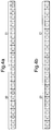
- Figure 4 illustrates the two types of S-field utilised under the DECT standard. One is used in transmissions by the fixed part ( Figure 4a) and the other for transmission by the handset Figure 4b. Both S-fields 11 are similar in that they include a preamble portion 20 used for 'lock' recovery, or bit synchronisation, and a synchronisation word 21 used for slot recovery. The preamble in each case is a sequence of zero/one transitions. If the synchronisation word detected is the known synchronisation word, bit synchronisation is confirmed and a known position within the burst has been established. The receiver uses the synchronisation word to locate the beginning of the A-field and the subsequent fields to obtain the information carried by the burst.
- Lock recovery can be achieved in a number of ways, one of which is illustrated in Figure 5.
- Figure 5 shows a sequence in which two 2x9 bit banks 30, 31 are seen for successive over sample periods for nine times oversampling a received signal.
- the incoming bit stream is sampled 9 times and the over-sampled 1s and 0s are stored in a bank of shift registers.
- the contents of the bank are compared each oversampled clock cycle until the 0-1 or 1-0 transition falls at the junction between two the bit banks.
- the banks contain respectively nine 0s and nine 1s the phase of the bit rate clock on the burst mode controller is shifted to comply with the phase of the clock cycle determined from the oversampling.
- This example uses nine times oversampling. Other oversampling rates could, however, be employed.
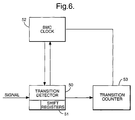
- Figures 6 shows an apparatus for determining a lock recovery point.
- Figure 6 shows a transition detector 50 receiving an incoming burst.
- the transition detector contains shift registers 51 and detects a transition when the two bit banks 30, 31 register a transition as explained previously.
- a transition is detected the phase of a clock 52 in the BMC is adjusted or reset.
- the number of zero-one transitions detected are counted by a transition counter 53.
- the transition counter 53 sends a signal to the BMC clock 52 to prevent it from being adjusted or reset further once a predetermined number of proper transitions have been identified by the transition detector 53.
- Figure 7 is a flow chart describing operation of the apparatus of Figure 6.
- the end of the synchronisation word could be detected and the number of counts to the beginning calculated by subtracting 16 bits from the end point.
- the number of bits to the synchronisation word can be determined in these or other ways. Other measures of the interval to the achievement of synchronisation could, instead, be employed.
- the oversample clock is increased by one 77 until another transition is detected 78.
- a determination is then made as to whether there have been exactly nine oversample bits since the last transition 79. If there have, the BMC clock is adjusted 71, the counter increased and the process continued to detect the next transition. If not, the counter is reset 80, and the oversample clock increased 77 until the next transition is detected 78. Once lock recovery has been achieved, the number of bits to the synchronisation word can be counted.
- the number of transitions between lock recovery and the synchronisation word are as follows: 8, 8, 7, 8, 8, 7, 8, 8, 7, 7, 6, 6, 6, 5, 5
- the increasing interval necessary to establish lock recovery indicates that perhaps the burst is undergoing a sliding collision eroding data at the front end of the burst.
- FIG. 8 An example of how this information can be used as a measure of signal quality is illustrated in Figure 8.
- the received signal is oversampled and a determination as to whether lock recovery has been achieved is made 91 by, for example, the method described in relation to Figure 7.
- the bit transitions are counted 92 until the beginning of the synchronisation word is identified.
- the achievement of slot synchronisation can be verified 93 and the received burst processed 94.
- a running average of the lock recovery point for the most recent four bursts for example, can be calculated 95 and a comparison with the lock recovery point for the two most recent bursts is made 96.
- the channel can again determined to be of poor quality and handover can be requested.
- the synchronisation field can be used simply as another error detection field.
- the synchronisation field is used as another error detection field the in-built hysterisis necessary for a determination that errors result from a permanent channel deterioration rather then fast fades or other temporary signal deteriorations will be necessary in order to prevent unnecessary handover as a result of fast fades or other temporary signal deteriorations.
- Suitable methods and apparatus for handing over are described in copending UK applications 9500799.3 and 9500619.3.
- the present invention includes any novel feature or combination of features disclosed herein either explicitly or any generalisation thereof irrespective of whether or not it relates to the claimed invention or mitigates any or all of the problems addressed.
Landscapes
- Engineering & Computer Science (AREA)
- Computer Networks & Wireless Communication (AREA)
- Signal Processing (AREA)
- Quality & Reliability (AREA)
- Mobile Radio Communication Systems (AREA)
- Time-Division Multiplex Systems (AREA)
Applications Claiming Priority (2)
| Application Number | Priority Date | Filing Date | Title |
|---|---|---|---|
| GB9601987 | 1996-01-31 | ||
| GB9601987A GB2309859B (en) | 1996-01-31 | 1996-01-31 | Radio receivers and methods of operation |
Publications (2)
| Publication Number | Publication Date |
|---|---|
| EP0788242A1 true EP0788242A1 (fr) | 1997-08-06 |
| EP0788242B1 EP0788242B1 (fr) | 1999-03-03 |
Family
ID=10787905
Family Applications (1)
| Application Number | Title | Priority Date | Filing Date |
|---|---|---|---|
| EP96309028A Expired - Lifetime EP0788242B1 (fr) | 1996-01-31 | 1996-12-11 | Radio-récepteur et méthode de mise en oeuvre |
Country Status (5)
| Country | Link |
|---|---|
| US (1) | US5991283A (fr) |
| EP (1) | EP0788242B1 (fr) |
| JP (1) | JP3672693B2 (fr) |
| DE (1) | DE69601620T2 (fr) |
| GB (1) | GB2309859B (fr) |
Cited By (1)
| Publication number | Priority date | Publication date | Assignee | Title |
|---|---|---|---|---|
| EP2299615A1 (fr) * | 2009-09-21 | 2011-03-23 | Imec | Circuit pour la detection de la fin d'une salve |
Families Citing this family (4)
| Publication number | Priority date | Publication date | Assignee | Title |
|---|---|---|---|---|
| US6738364B1 (en) * | 1996-01-31 | 2004-05-18 | Nokia Mobile Phones Limited | Radio receivers and methods of operation |
| DE10040222A1 (de) * | 2000-08-17 | 2002-02-28 | Marconi Comm Gmbh | Verfahren zum Betreiben eines Nachrichten-Empfängers |
| US7320094B2 (en) * | 2003-07-22 | 2008-01-15 | Intel Corporation | Retraining derived clock receivers |
| TWI246339B (en) * | 2004-09-17 | 2005-12-21 | Realtek Semiconductor Corp | Evaluation method for signal transmission quality and tuning method thereof |
Citations (2)
| Publication number | Priority date | Publication date | Assignee | Title |
|---|---|---|---|---|
| US5054035A (en) * | 1989-12-21 | 1991-10-01 | At&T Bell Laboratories | Digital signal quality evaluation circuit using synchronization patterns |
| EP0472511A2 (fr) * | 1990-08-23 | 1992-02-26 | Telefonaktiebolaget L M Ericsson | Basculement d'une station mobile entre canaux à débits moitié et nominal |
Family Cites Families (14)
| Publication number | Priority date | Publication date | Assignee | Title |
|---|---|---|---|---|
| GB2232326A (en) * | 1989-05-26 | 1990-12-05 | Philips Electronic Associated | Data transmission over a tdm duplex frequency channel |
| SE500157C2 (sv) * | 1989-09-13 | 1994-04-25 | Ericsson Telefon Ab L M | Förfarande för att välja basstation, radiokanal och tidslucka vid en mobilstation |
| JP3093243B2 (ja) * | 1990-07-12 | 2000-10-03 | 株式会社東芝 | 移動無線通信システム |
| GB2249918A (en) * | 1990-11-14 | 1992-05-20 | Philips Electronic Associated | Channel scanning in tdd cordless telephone system |
| US5214687A (en) * | 1991-06-05 | 1993-05-25 | Nokia Mobile Phones Ltd. | Method to determine transmission quality |
| IT1250515B (it) * | 1991-10-07 | 1995-04-08 | Sixtel Spa | Rete per area locale senza fili. |
| US5276691A (en) * | 1992-01-21 | 1994-01-04 | Nokia Mobile Phones Ltd. | Method for the control of receiver synchronization in a mobile phone |
| US5333153A (en) * | 1992-01-21 | 1994-07-26 | Motorola, Inc. | Signal quality detection method and apparatus for optimum audio muting |
| US5416778A (en) * | 1992-06-26 | 1995-05-16 | U.S. Philips Corporation | Digital radio communication system and primary and secondary station for use in such a system |
| US6088590A (en) * | 1993-11-01 | 2000-07-11 | Omnipoint Corporation | Method and system for mobile controlled handoff and link maintenance in spread spectrum communication |
| US5598431A (en) * | 1994-12-23 | 1997-01-28 | Motorola, Inc. | Method and apparatus for signal quality detection in a communication system |
| GB2297014B (en) * | 1995-01-10 | 1999-07-28 | Nokia Mobile Phones Ltd | Portable radio telephones and method of operation |
| GB2297013B (en) * | 1995-01-10 | 1999-09-15 | Nokia Mobile Phones Ltd | Portable radio telephones and methods of operation |
| US5666366A (en) * | 1996-05-24 | 1997-09-09 | National Semiconductor Corporation | Inter-base synchronization technique for a TDMA communication system |
-
1996
- 1996-01-31 GB GB9601987A patent/GB2309859B/en not_active Expired - Fee Related
- 1996-12-11 DE DE69601620T patent/DE69601620T2/de not_active Expired - Lifetime
- 1996-12-11 EP EP96309028A patent/EP0788242B1/fr not_active Expired - Lifetime
-
1997
- 1997-01-17 US US08/784,974 patent/US5991283A/en not_active Expired - Fee Related
- 1997-01-30 JP JP01614297A patent/JP3672693B2/ja not_active Expired - Fee Related
Patent Citations (2)
| Publication number | Priority date | Publication date | Assignee | Title |
|---|---|---|---|---|
| US5054035A (en) * | 1989-12-21 | 1991-10-01 | At&T Bell Laboratories | Digital signal quality evaluation circuit using synchronization patterns |
| EP0472511A2 (fr) * | 1990-08-23 | 1992-02-26 | Telefonaktiebolaget L M Ericsson | Basculement d'une station mobile entre canaux à débits moitié et nominal |
Cited By (3)
| Publication number | Priority date | Publication date | Assignee | Title |
|---|---|---|---|---|
| EP2299615A1 (fr) * | 2009-09-21 | 2011-03-23 | Imec | Circuit pour la detection de la fin d'une salve |
| US8380079B2 (en) | 2009-09-21 | 2013-02-19 | Imec | Circuit for end-of-burst detection |
| EP2375601A1 (fr) * | 2010-03-22 | 2011-10-12 | Imec | Circuit pour la detection de la fin d'une salve |
Also Published As
| Publication number | Publication date |
|---|---|
| DE69601620D1 (de) | 1999-04-08 |
| GB2309859A (en) | 1997-08-06 |
| EP0788242B1 (fr) | 1999-03-03 |
| GB9601987D0 (en) | 1996-04-03 |
| DE69601620T2 (de) | 1999-07-22 |
| US5991283A (en) | 1999-11-23 |
| JP3672693B2 (ja) | 2005-07-20 |
| JPH09214416A (ja) | 1997-08-15 |
| GB2309859B (en) | 2000-02-16 |
Similar Documents
| Publication | Publication Date | Title |
|---|---|---|
| US6032033A (en) | Preamble based selection diversity in a time division multiple access radio system using digital demodulation | |
| US5109393A (en) | Mobile communications system insensitive to false frame sync | |
| US8125934B2 (en) | System and method for synchronization signal detection and recovery from false triggers | |
| EP1044518B1 (fr) | Systeme ameliore de commutation d'antenne en diversite pour telephones amrt | |
| WO1994008404A1 (fr) | Systemes d'atennes multiples dans les communications privees par radio | |
| WO1999001000A2 (fr) | Procede d'identification de stations de base d'un reseau cellulaire a division dans le temps dans une station mobile et station mobile ainsi conçue | |
| US6738364B1 (en) | Radio receivers and methods of operation | |
| US6317424B1 (en) | Antenna diversity radio receiving arrangement for telecommunications systems using block-oriented transmission of radio messages | |
| US5436937A (en) | Multi-mode digital phase lock loop | |
| JP4221460B2 (ja) | 移動局を基地局と同期させるための方法 | |
| EP0863686A2 (fr) | Système d'accès à un réseau de radiocommunication sectorisé | |
| EP0788255B1 (fr) | Radio téléphone avec synchronisation protégée contre les erreurs | |
| JP2912097B2 (ja) | 判断指向クロック回復システムを変更するための方法及び装置 | |
| EP0788242B1 (fr) | Radio-récepteur et méthode de mise en oeuvre | |
| US6091718A (en) | Radio receivers and methods of operation | |
| US5598446A (en) | Clock extraction of a clock signal using rising and falling edges of a received transmission signal | |
| KR100354196B1 (ko) | 무선통신시스템및그시스템용무선국 | |
| US5841823A (en) | Method and apparatus for extracting a clock signal from a received signal | |
| EP0757501B1 (fr) | Radio-téléphone et procédé de fonctionnement | |
| US6674735B1 (en) | Radio receivers and methods of operation | |
| US6154457A (en) | Mobile station having improved DCCH synchronization | |
| AU9430598A (en) | Method and apparatus for controlling the reception of data packets in a mobile station | |
| US20020110208A1 (en) | Frame synchronizing signal detecting method for reducing occurrence of error synchronization before link of frame synchronizing signal is established | |
| EP1396955B1 (fr) | Circuit de mesure du taux d'erreur binaire en cas d'absence de synchronisation | |
| JPH09307531A (ja) | ビット誤り率測定方法およびその装置 |
Legal Events
| Date | Code | Title | Description |
|---|---|---|---|
| PUAI | Public reference made under article 153(3) epc to a published international application that has entered the european phase |
Free format text: ORIGINAL CODE: 0009012 |
|
| AK | Designated contracting states |
Kind code of ref document: A1 Designated state(s): DE FR NL SE |
|
| 17P | Request for examination filed |
Effective date: 19980206 |
|
| 17Q | First examination report despatched |
Effective date: 19980403 |
|
| GRAG | Despatch of communication of intention to grant |
Free format text: ORIGINAL CODE: EPIDOS AGRA |
|
| GRAG | Despatch of communication of intention to grant |
Free format text: ORIGINAL CODE: EPIDOS AGRA |
|
| GRAH | Despatch of communication of intention to grant a patent |
Free format text: ORIGINAL CODE: EPIDOS IGRA |
|
| GRAH | Despatch of communication of intention to grant a patent |
Free format text: ORIGINAL CODE: EPIDOS IGRA |
|
| GRAA | (expected) grant |
Free format text: ORIGINAL CODE: 0009210 |
|
| AK | Designated contracting states |
Kind code of ref document: B1 Designated state(s): DE FR NL SE |
|
| REF | Corresponds to: |
Ref document number: 69601620 Country of ref document: DE Date of ref document: 19990408 |
|
| ET | Fr: translation filed | ||
| PLBE | No opposition filed within time limit |
Free format text: ORIGINAL CODE: 0009261 |
|
| STAA | Information on the status of an ep patent application or granted ep patent |
Free format text: STATUS: NO OPPOSITION FILED WITHIN TIME LIMIT |
|
| 26N | No opposition filed | ||
| PGFP | Annual fee paid to national office [announced via postgrant information from national office to epo] |
Ref country code: SE Payment date: 20091207 Year of fee payment: 14 |
|
| PGFP | Annual fee paid to national office [announced via postgrant information from national office to epo] |
Ref country code: NL Payment date: 20091204 Year of fee payment: 14 |
|
| PGFP | Annual fee paid to national office [announced via postgrant information from national office to epo] |
Ref country code: FR Payment date: 20091221 Year of fee payment: 14 |
|
| PGFP | Annual fee paid to national office [announced via postgrant information from national office to epo] |
Ref country code: DE Payment date: 20091203 Year of fee payment: 14 |
|
| REG | Reference to a national code |
Ref country code: NL Ref legal event code: V1 Effective date: 20110701 |
|
| REG | Reference to a national code |
Ref country code: FR Ref legal event code: ST Effective date: 20110831 |
|
| REG | Reference to a national code |
Ref country code: SE Ref legal event code: EUG |
|
| PG25 | Lapsed in a contracting state [announced via postgrant information from national office to epo] |
Ref country code: SE Free format text: LAPSE BECAUSE OF NON-PAYMENT OF DUE FEES Effective date: 20101212 |
|
| PG25 | Lapsed in a contracting state [announced via postgrant information from national office to epo] |
Ref country code: FR Free format text: LAPSE BECAUSE OF NON-PAYMENT OF DUE FEES Effective date: 20110103 |
|
| REG | Reference to a national code |
Ref country code: DE Ref legal event code: R119 Ref document number: 69601620 Country of ref document: DE Effective date: 20110701 |
|
| PG25 | Lapsed in a contracting state [announced via postgrant information from national office to epo] |
Ref country code: DE Free format text: LAPSE BECAUSE OF NON-PAYMENT OF DUE FEES Effective date: 20110701 |
|
| PG25 | Lapsed in a contracting state [announced via postgrant information from national office to epo] |
Ref country code: NL Free format text: LAPSE BECAUSE OF NON-PAYMENT OF DUE FEES Effective date: 20110701 |