EP0788250A2 - Interface optique pour diagnostiques d'une commande optoélectronique de points de cuisson - Google Patents
Interface optique pour diagnostiques d'une commande optoélectronique de points de cuisson Download PDFInfo
- Publication number
- EP0788250A2 EP0788250A2 EP97100681A EP97100681A EP0788250A2 EP 0788250 A2 EP0788250 A2 EP 0788250A2 EP 97100681 A EP97100681 A EP 97100681A EP 97100681 A EP97100681 A EP 97100681A EP 0788250 A2 EP0788250 A2 EP 0788250A2
- Authority
- EP
- European Patent Office
- Prior art keywords
- receiver
- transmitter
- optical interface
- feature
- optoelectronic
- Prior art date
- Legal status (The legal status is an assumption and is not a legal conclusion. Google has not performed a legal analysis and makes no representation as to the accuracy of the status listed.)
- Withdrawn
Links
- 230000003287 optical effect Effects 0.000 title claims abstract description 18
- 230000005693 optoelectronics Effects 0.000 title claims abstract description 7
- 238000010411 cooking Methods 0.000 title 1
- 238000003745 diagnosis Methods 0.000 title 1
- 230000005540 biological transmission Effects 0.000 claims abstract description 12
- 239000000919 ceramic Substances 0.000 claims abstract description 10
- 230000001681 protective effect Effects 0.000 claims description 5
- 230000002457 bidirectional effect Effects 0.000 claims 1
- 230000008878 coupling Effects 0.000 description 2
- 238000010168 coupling process Methods 0.000 description 2
- 238000005859 coupling reaction Methods 0.000 description 2
- 238000010586 diagram Methods 0.000 description 2
- 230000005855 radiation Effects 0.000 description 2
- 230000006978 adaptation Effects 0.000 description 1
- 238000004519 manufacturing process Methods 0.000 description 1
- 238000004886 process control Methods 0.000 description 1
Images

Classifications
-
- G—PHYSICS
- G08—SIGNALLING
- G08C—TRANSMISSION SYSTEMS FOR MEASURED VALUES, CONTROL OR SIMILAR SIGNALS
- G08C23/00—Non-electrical signal transmission systems, e.g. optical systems
- G08C23/04—Non-electrical signal transmission systems, e.g. optical systems using light waves, e.g. infrared
-
- H—ELECTRICITY
- H05—ELECTRIC TECHNIQUES NOT OTHERWISE PROVIDED FOR
- H05B—ELECTRIC HEATING; ELECTRIC LIGHT SOURCES NOT OTHERWISE PROVIDED FOR; CIRCUIT ARRANGEMENTS FOR ELECTRIC LIGHT SOURCES, IN GENERAL
- H05B3/00—Ohmic-resistance heating
- H05B3/68—Heating arrangements specially adapted for cooking plates or analogous hot-plates
- H05B3/74—Non-metallic plates, e.g. vitroceramic, ceramic or glassceramic hobs, also including power or control circuits
-
- G—PHYSICS
- G08—SIGNALLING
- G08C—TRANSMISSION SYSTEMS FOR MEASURED VALUES, CONTROL OR SIMILAR SIGNALS
- G08C2201/00—Transmission systems of control signals via wireless link
- G08C2201/20—Binding and programming of remote control devices
- G08C2201/21—Programming remote control devices via third means
-
- G—PHYSICS
- G08—SIGNALLING
- G08C—TRANSMISSION SYSTEMS FOR MEASURED VALUES, CONTROL OR SIMILAR SIGNALS
- G08C2201/00—Transmission systems of control signals via wireless link
- G08C2201/50—Receiving or transmitting feedback, e.g. replies, status updates, acknowledgements, from the controlled devices
Definitions
- the invention relates to an optical interface, in particular for diagnosing an optoelectronic hotplate control, according to claim 1.
- an external programming device for data input or output for programming systems for process control or the like is known, its coupling to the unit to be programmed as an optically working interface with mutually closed contact surfaces and mutually assignable light Transmitters or light sensors.
- such an optical interface in particular when applied to an external programming and / or diagnostic unit for an optical hotplate controller covered by a protective pane, is to be upgraded with a view to high insensitivity to external or stray influences.
- the coupling according to the invention between a programming and / or diagnostic unit on the one hand and a control unit on the other hand ensures a high transmission quality of the transmitted pulse-width-modulated signals, despite the fact that a mutual galvanic connection is advantageous for simple handling, since the high steepness of the edge means that it is conventional and has no steep edges Ambient light and the high pulse amplitude of transmission pulses from conventional remote controls that are usually not in the immediate vicinity have no influence.
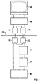
- FIG. 1 shows in the structural application configuration and FIG. 3 in the associated block diagram shows an optical interface between an external programming and / or diagnostic unit DE above a radiation-permeable ceramic pane CE provided as a protective cover and a control unit MC in the form of a microcontroller below the ceramic pane.
- Disc CE as a component of an optoelectronic hotplate control arranged and connected on a circuit board (PL) with a plurality of optoelectronic touch keys (not shown here).
- a first transmitter S1 and a first receiver E1 are used for optical transmission on the upper side of the ceramic disc CE and a second receiver E2 assigned to the first transmitter S1 and a second transmitter S2 assigned to the first receiver E1 are located below the ceramic disc CE.
- the second transmitter S2 and the second receiver E2 are connected to a serial interface output of the microcontroller, which a controller of this type, including the necessary test software, generally has.
- the latter advantageously remains blocked during the transmission time of the activated transmitter; the data are transmitted in half-duplex mode, in which only one of the participants alternately transmits, while the other participant only receives.
- an interface converter SW is provided on the external side between the first transmitter S1 and the first receiver E1, on the one hand, and the external programming and / or diagnostic unit DE, on the other hand, which converts or outputs the programming and / or diagnostic unit DE. incoming signals converted to the so-called TTL level.
- this microcontroller itself can be used as a diagnostic component, in particular during the production process, in order to be able to check the correct functioning of the entire hotplate control; In addition, an initialization or update of operating parameters and, if necessary, customer service can be quickly localized, the errors are possible.
- FIG. 2 shows in its upper first picture the example of a pulse train for a pulse-width-modulated signal which can be transmitted without interference via the first transmitter S1 to the second receiver E2 by means of infrared radiation through the ceramic disc CE and for a specific command configuration in the microcontroller MC the control unit, which in turn can then provide feedback via the second transmitter S2 by infrared radiation through the ceramic disc CE to the first receiver E1 and thus to the programming and / or diagnostic unit.
- the output signals are usually set to high, the data bits to active low.
- an infrared LED provided as the first transmitter S1 is pulsed, whereby no current flows during the transmission pole breaks, but a short current surge is generated during the respective pulse-compliant switch-on in such a way that the necessary high slope and high pulse amplitude is achieved;
- the infrared signal formed in this way is shown with a steep flank during the respective pulse change in accordance with the first signal curve.
- the corresponding signal arriving below the ceramic disc CE at the second receiver E2 is made up of the signal emitted by the first transmitter S1 with increased edge steepness and pulse amplitude and a superimposed noise caused by disturbance variables such as e.g. Room lighting and remote controls together.
- This signal is the input signal of a differentiator DI downstream of the second receiver E2, the output signal of which is a function of the steepness of its input signals.
- a signal change corresponding to the processed pulse edges of the signal curve in the first image leads to a short output pulse with a high amplitude, while a slow signal change only leads to a small output amplitude. This last state of affairs is indicated in the waveform of the fourth image in FIG. 2.
- the differentiator DE is assigned a Schmitt trigger ST with an upper and a lower switching threshold, indicated with a dashed curve in the fourth image, by means of which the original pulse-width-modulated signal according to the signal curve in the fifth image can be back-modulated that a pulse edge is set by a large output amplitude each time a switching threshold is reached.
Landscapes
- Chemical & Material Sciences (AREA)
- Engineering & Computer Science (AREA)
- Ceramic Engineering (AREA)
- Physics & Mathematics (AREA)
- General Physics & Mathematics (AREA)
- Optical Communication System (AREA)
- Cookers (AREA)
Applications Claiming Priority (2)
| Application Number | Priority Date | Filing Date | Title |
|---|---|---|---|
| DE19603295 | 1996-01-30 | ||
| DE1996103295 DE19603295A1 (de) | 1996-01-30 | 1996-01-30 | Optische Schnittstelle, insbesondere zur Diagnose einer optoelektronischen Kochstellensteuerung |
Publications (2)
| Publication Number | Publication Date |
|---|---|
| EP0788250A2 true EP0788250A2 (fr) | 1997-08-06 |
| EP0788250A3 EP0788250A3 (fr) | 2001-11-07 |
Family
ID=7784046
Family Applications (1)
| Application Number | Title | Priority Date | Filing Date |
|---|---|---|---|
| EP97100681A Withdrawn EP0788250A3 (fr) | 1996-01-30 | 1997-01-17 | Interface optique pour diagnostiques d'une commande optoélectronique de points de cuisson |
Country Status (2)
| Country | Link |
|---|---|
| EP (1) | EP0788250A3 (fr) |
| DE (1) | DE19603295A1 (fr) |
Cited By (1)
| Publication number | Priority date | Publication date | Assignee | Title |
|---|---|---|---|---|
| FR2866512A1 (fr) * | 2004-02-12 | 2005-08-19 | Jaeger Controls | Systeme de table de cuisson electrique |
Families Citing this family (3)
| Publication number | Priority date | Publication date | Assignee | Title |
|---|---|---|---|---|
| DE19619927C2 (de) * | 1996-05-17 | 1998-06-04 | Siemens Ag | Optische Schnittstelle |
| DE29818520U1 (de) | 1998-10-20 | 1999-02-11 | industrie automation Energiesysteme GmbH & Co, 79232 March | Einrichtung zur Datenübertragung und zur Freigabe von Funktionen eines Gerätes |
| DE10220723B4 (de) * | 2002-05-10 | 2005-07-28 | Diehl Ako Stiftung & Co. Kg | Verfahren zur drahtlosen Datenübertragung |
Citations (1)
| Publication number | Priority date | Publication date | Assignee | Title |
|---|---|---|---|---|
| DE3921344A1 (de) | 1989-06-29 | 1991-01-10 | Hengstler Gmbh | Externes programmiergeraet |
Family Cites Families (15)
| Publication number | Priority date | Publication date | Assignee | Title |
|---|---|---|---|---|
| DE3243517A1 (de) * | 1982-11-25 | 1984-05-30 | Peter Prof.Dr. Russer | Elektrooptische empfangsantenne |
| DE3717591A1 (de) * | 1987-05-25 | 1988-12-08 | Hartmann & Braun Ag | Schaltungsanordnung zur potentialfreien erfassung von binaeren signalen |
| FR2622754B1 (fr) * | 1987-10-29 | 1990-01-12 | Alcatel Espace | Systeme de transmission radiofrequence-optique, notamment dans le domaine des telecommunications spatiales |
| DE3909126C2 (de) * | 1989-03-20 | 1998-06-04 | Diehl Gmbh & Co | Schaltgerät für einen Kochherd |
| US5142397A (en) * | 1990-01-04 | 1992-08-25 | Dockery Devan T | System for extending the effective operational range of an infrared remote control system |
| DE4019224A1 (de) * | 1990-06-15 | 1991-12-19 | Standard Elektrik Lorenz Ag | Funk-nachrichtenuebertragungssystem, insbesondere zellulares mobilfunksystem |
| US5315645A (en) * | 1990-12-10 | 1994-05-24 | Tek Electronics Manufacturing Corporation | Communication apparatus utilizing digital optical signals |
| ES2048106B1 (es) * | 1992-07-03 | 1995-06-16 | Balay Sa | Sistema para el control remoto de electrodomesticos. |
| FI109496B (fi) * | 1992-08-18 | 2002-08-15 | Nokia Corp | Laitteisto ja menetelmä digitaalisen infrapunavälitteisen tiedonsiirron järjestämiseksi radiopuhelinlaitteen perusosan ja toisen laitteen välillä |
| US5383044B1 (en) * | 1992-09-18 | 1998-09-01 | Recoton Corp | Systems methods and apparatus for transmitting radio frequency remote control signals |
| DE4310230C2 (de) * | 1992-11-26 | 1997-09-11 | Sel Alcatel Ag | Tragbares Teilnehmerendgerät für den Mobilfunk |
| JPH06216778A (ja) * | 1993-01-14 | 1994-08-05 | Mitsubishi Electric Corp | 通信制御装置の復調回路 |
| US5349162A (en) * | 1993-04-05 | 1994-09-20 | Whirlpool Corporation | Fault detection method and apparatus for a domestic appliance |
| DE4433896C1 (de) * | 1994-09-22 | 1995-11-09 | Siemens Ag | Verfahren und Kommunikationssystem zur Reduzierung der Funkübertragungen in drahtlosen Kommunikationssystemen |
| DE9416779U1 (de) * | 1994-10-18 | 1994-12-08 | Bosch-Siemens Hausgeräte GmbH, 81669 München | Sensorgesteuerte Glaskeramik-Kochstelleneinheit |
-
1996
- 1996-01-30 DE DE1996103295 patent/DE19603295A1/de not_active Ceased
-
1997
- 1997-01-17 EP EP97100681A patent/EP0788250A3/fr not_active Withdrawn
Patent Citations (1)
| Publication number | Priority date | Publication date | Assignee | Title |
|---|---|---|---|---|
| DE3921344A1 (de) | 1989-06-29 | 1991-01-10 | Hengstler Gmbh | Externes programmiergeraet |
Cited By (1)
| Publication number | Priority date | Publication date | Assignee | Title |
|---|---|---|---|---|
| FR2866512A1 (fr) * | 2004-02-12 | 2005-08-19 | Jaeger Controls | Systeme de table de cuisson electrique |
Also Published As
| Publication number | Publication date |
|---|---|
| DE19603295A1 (de) | 1997-07-31 |
| EP0788250A3 (fr) | 2001-11-07 |
Similar Documents
| Publication | Publication Date | Title |
|---|---|---|
| DE4036407C2 (de) | Sensorsystem | |
| WO2003030363A2 (fr) | Circuit pourvu d'une unite d'indication optoelectronique | |
| EP4080252A1 (fr) | Rideau lumineux | |
| EP0788250A2 (fr) | Interface optique pour diagnostiques d'une commande optoélectronique de points de cuisson | |
| EP2413667B1 (fr) | Dispositif de commande pour la commande d'une lampe et lampe | |
| EP2056125B1 (fr) | Capteur | |
| DE3637689C1 (de) | Faseroptische Messwerterfassungs- und Uebertragungseinrichtung | |
| DE10211387A1 (de) | Strahlungsimpulse verwendender Sensor | |
| EP3796052B1 (fr) | Agencement de capteur optoélectronique et système de capteur | |
| DE10045097B4 (de) | Sensorkopf, Steuermodul und Mehrfachsensor | |
| DE19619927C2 (de) | Optische Schnittstelle | |
| DE19743981A1 (de) | Verfahren zur Adressierung eines Aktuator-Sensor-Slaves sowie Aktuator-Sensor-Slave und Adressiergerät zur Durchführung des Verfahrens | |
| DE19747248A1 (de) | Reflexionslichtschranke | |
| DE202010008049U1 (de) | Sicherheitslichtgitter | |
| DE19547301C1 (de) | Betätigungsvorrichtung mit zumindest einem optoelektronischen Tastenelement | |
| DE10349978B3 (de) | System, bestehend aus einem Haushaltsgerät und einem externen Gerät | |
| EP0808038A2 (fr) | Dispositif d'affichage avec illumination d'affichage adaptée à la luminosité | |
| EP1598959B1 (fr) | Module d'émission optique | |
| DE3545194C2 (fr) | ||
| EP0779712A1 (fr) | Micro-contrÔleur pour un appareil ménager | |
| DE10245505B4 (de) | Vorrichtung zur Übertragung digitaler Signale zwischen beweglichen Einheiten mit analoger Filterung | |
| DE19547300C1 (de) | Betätigungsvorrichtung mit zumindest einem optoelektronischen Tastenelement | |
| EP1633047A2 (fr) | Commutateur à touche tactile | |
| DE102004042657B4 (de) | Berührungsempfindlicher Tastschalter | |
| DE19852754A1 (de) | Vorrichtung zum Aussenden von optischen Signalen an einen externen technischen Prozeß und/oder zum Empfangen von optischen Signalen von einem externen technischen Prozeß |
Legal Events
| Date | Code | Title | Description |
|---|---|---|---|
| PUAI | Public reference made under article 153(3) epc to a published international application that has entered the european phase |
Free format text: ORIGINAL CODE: 0009012 |
|
| AK | Designated contracting states |
Kind code of ref document: A2 Designated state(s): DE FR GB IT |
|
| RAP1 | Party data changed (applicant data changed or rights of an application transferred) |
Owner name: BSH BOSCH UND SIEMENS HAUSGERAETE GMBH |
|
| PUAL | Search report despatched |
Free format text: ORIGINAL CODE: 0009013 |
|
| AK | Designated contracting states |
Kind code of ref document: A3 Designated state(s): DE FR GB IT |
|
| RIC1 | Information provided on ipc code assigned before grant |
Free format text: 7H 04B 10/10 A, 7H 04L 25/49 B, 7H 05B 3/74 B |
|
| 17P | Request for examination filed |
Effective date: 20020507 |
|
| RAP1 | Party data changed (applicant data changed or rights of an application transferred) |
Owner name: BSH BOSCH UND SIEMENS HAUSGERAETE GMBH |
|
| 17Q | First examination report despatched |
Effective date: 20070830 |
|
| STAA | Information on the status of an ep patent application or granted ep patent |
Free format text: STATUS: THE APPLICATION IS DEEMED TO BE WITHDRAWN |
|
| 18D | Application deemed to be withdrawn |
Effective date: 20070801 |