EP0788434B1 - Dynamsiches vielfarbendruckverfahren und vorrichtung - Google Patents
Dynamsiches vielfarbendruckverfahren und vorrichtung Download PDFInfo
- Publication number
- EP0788434B1 EP0788434B1 EP96927891A EP96927891A EP0788434B1 EP 0788434 B1 EP0788434 B1 EP 0788434B1 EP 96927891 A EP96927891 A EP 96927891A EP 96927891 A EP96927891 A EP 96927891A EP 0788434 B1 EP0788434 B1 EP 0788434B1
- Authority
- EP
- European Patent Office
- Prior art keywords
- positive electrode
- electrode active
- active surface
- colloid
- onto
- Prior art date
- Legal status (The legal status is an assumption and is not a legal conclusion. Google has not performed a legal analysis and makes no representation as to the accuracy of the status listed.)
- Expired - Lifetime
Links
Images


Classifications
-
- B—PERFORMING OPERATIONS; TRANSPORTING
- B41—PRINTING; LINING MACHINES; TYPEWRITERS; STAMPS
- B41M—PRINTING, DUPLICATING, MARKING, OR COPYING PROCESSES; COLOUR PRINTING
- B41M5/00—Duplicating or marking methods; Sheet materials for use therein
- B41M5/20—Duplicating or marking methods; Sheet materials for use therein using electric current
-
- B—PERFORMING OPERATIONS; TRANSPORTING
- B41—PRINTING; LINING MACHINES; TYPEWRITERS; STAMPS
- B41C—PROCESSES FOR THE MANUFACTURE OR REPRODUCTION OF PRINTING SURFACES
- B41C1/00—Forme preparation
- B41C1/10—Forme preparation for lithographic printing; Master sheets for transferring a lithographic image to the forme
- B41C1/105—Forme preparation for lithographic printing; Master sheets for transferring a lithographic image to the forme by electrocoagulation, by electro-adhesion or by electro-releasing of material, e.g. a liquid from a gel
-
- B—PERFORMING OPERATIONS; TRANSPORTING
- B41—PRINTING; LINING MACHINES; TYPEWRITERS; STAMPS
- B41J—TYPEWRITERS; SELECTIVE PRINTING MECHANISMS, i.e. MECHANISMS PRINTING OTHERWISE THAN FROM A FORME; CORRECTION OF TYPOGRAPHICAL ERRORS
- B41J2/00—Typewriters or selective printing mechanisms characterised by the printing or marking process for which they are designed
- B41J2/315—Typewriters or selective printing mechanisms characterised by the printing or marking process for which they are designed characterised by selective application of heat to a heat sensitive printing or impression-transfer material
- B41J2/32—Typewriters or selective printing mechanisms characterised by the printing or marking process for which they are designed characterised by selective application of heat to a heat sensitive printing or impression-transfer material using thermal heads
- B41J2/325—Typewriters or selective printing mechanisms characterised by the printing or marking process for which they are designed characterised by selective application of heat to a heat sensitive printing or impression-transfer material using thermal heads by selective transfer of ink from ink carrier, e.g. from ink ribbon or sheet
Definitions
- the present invention pertains to improvements in the field of dynamic printing. More particularly, the invention relates to an improved multicolor electrocoagulation printing method and apparatus.
- the positive electrode is coated with a dispersion containing an olefinic substance and a metal oxide prior to electrical energization of the negative electrodes in order to weaken the adherence of the dots of coagulated colloid to the positive electrode and also to prevent an uncontrolled corrosion of the positive electrode.
- gas generated as a result of electrolysis upon energizing the negative electrodes is consumed by reaction with the olefinic substance so that there is no gas accumulation between the negative and positive electrodes.
- the dispersion containing the olefinic substance and the metal oxide is applied onto the surface of the positive electrode in a manner so as to form on the electrode surface micro-droplets of olefinic substance containing the metal oxide.
- this may be achieved by means of a device comprising a rotatable brush provided with a plurality of radially extending horsehair bristles having extremities contacting the electrode surface, and a distribution roller arranged in spaced-apart parallel relation to the brush such as to contact the bristles thereof at their extremities.
- the distribution roller has a plurality of peripheral longitudinally extending grooves and is partially immersed in a bath containing the dispersion.
- the grooves are filled with the dispersion which is thus transferred to the bristles to coat the extremities thereof.
- Rotation of the brush causes the coated bristles to transfer the dispersion onto the surface of the positive electrode and thereby form the desired micro-droplets of olefinic substance containing the metal oxide.
- a brush use can be made of a roller provided with a plurality of radially extending strips of chamois leather adapted to contact the electrode surface, the strips being coated in the same manner as the bristles. Rotation of such a roller causes the coated strips to impinge upon the surface of the positive electrode such as to transfer thereon the dispersion and thereby form the desired micro-droplets of olefinic substance containing the metal oxide.
- the electrocoagulation printing ink which is injected into the gap defined between the positive and negative electrodes consists essentially of a liquid colloidal dispersion containing an electrolytically coagulable colloid, a dispersing medium, a soluble electrolyte and a coloring agent. Where a pigment is used, a dispersing agent is added for uniformly dispersing the pigment into the ink.
- the negative and positive electrodes, the positive electrode coating device and the ink injector are arranged to define a printing unit and several printing units each using a coloring agent of different color are disposed in tandem relation to produce several differently colored images of coagulated colloid which are transferred at respective transfer stations onto the substrate in superimposed relation to provide the desired polychromic image.
- the printing units can be arranged around a single roller adapted to bring the substrate into contact with the dots of colored, coagulated colloid produced by each printing unit, and the substrate which is in the form of a continuous web is partially wrapped around the roller and passed through the respective transfer stations for being imprinted with the differently colored images in superimposed relation.
- each printing unit of the above multicolor printing apparatus requires a high precision cylinder which is usually in stainless steel, as a positive electrode, such an apparatus is not only cumbersome but also very costly.
- high precision cylinders are required for forming differently coloured images of coagulated colloid, it is difficult to provide a polychromic image in which the differently coloured images are perfectly superimposed.
- a multicolour electrocoagulation printing method comprising the steps of: a) providing a single positive electrode formed of an electrolytically inert metal and having a continuous passivated surface moving at substantially constant speed along a predetermined path, said passivated surface defining a positive electrode active surface; b) forming on said positive electrode active surface a plurality of dots of coloured, coagulated colloid by electrocoagulation of an electrolytically coagulable colloid in the presence of a colouring agent, said dots of coloured, coagulated colloid being representative of a desired image; c) bringing a substrate into contact with the dots of coloured, coagulated colloid to cause transfer of the coloured, coagulated colloid from the positive electrode active surface onto said substrate and thereby imprint said substrate with the image; and d) repeating steps (b) and (c) several times to define a corresponding number of printing stages arranged at predetermined locations along said path and each using a colouring agent of different colour, and to thereby produce several differently
- multicolour electrocoagulation printing apparatus comprising: a single positive electrode formed of an electrolytically inert metal and having a continuous passivated surface defining a positive electrode active surface; means for moving said positive electrode active surface at a substantially constant speed along a predetermined path; and a plurality of printing units arranged at predetermined locations along said path, each printing unit comprising: means for forming on said positive electrode active surface a plurality of dots of coloured, coagulated colloid by electrocoagulation of an electrolytically coagulable colloid in the presence of a colouring agent of different colour, said dots of coloured, coagulated colloid being representative of a desired image; and means for bringing a substrate into contact with the dots of coloured, coagulated colloid at a respective transfer station to cause transfer of the coloured, coagulated colloid from the positive electrode active surface onto said substrate and thereby imprint said substrate with the image.
- the electrocoagulation printing method and apparatus to be described utilize a single positive electrode on which dots of coloured, coagulated colloid are formed in sequence and the substrate which is generally in the form of a web travels independently of the positive electrode, from one printing unit to another, so as to contact the coloured, coagulated colloid in sequence.
- the invention enables one to significantly improve the registration of the differently coloured images upon their transfer onto the web or other substrate, thereby providing a polychromic image of high definition.
- the positive electrode used can be in the form of a moving endless belt as described in Applicant's US Patent No. 4,661,222, or in the form of a revolving cylinder as described in the aforementioned US Patent No. 4,895,629.
- the printing units are arranged around the positive cylindrical electrode.
- step (b) of the above electrocoagulation printing method is carried out by:
- Suitable electrolytically inert metals from which the positive and negative electrodes can be made are stainless steel, platinum, chromium, nickel and aluminum.
- the positive electrode is preferably made of stainless steel or aluminum so that upon electrical energization of the negative electrodes, dissolution of the passive oxide film on such an electrode generates trivalent ions which then initiate coagulation of the colloid.
- the gap which is defined between the positive and negative electrodes can range from about 50 ⁇ to about 100 ⁇ , the smaller the electrode gap the sharper are the dots of coagulated colloid produced. Where the electrode gap is of the order of 50 ⁇ , the negative electrodes are the preferably spaced from one another by a distance of about 75 ⁇ .
- Suitable olefinic substances which may be used to coat the surface of the positive electrode include unsaturated fatty acids such as arachidonic acid, linoleic acid, linolenic acid, oleic acid and palmitoleic acid and unsaturated vegetable oils such as corn oil, linseed oil, olive oil, peanut oil, soybean oil and sunflower oil.
- the olefinic substance is advantageously applied onto the positive electrode active surface in the form of an oily dispersion containing the metal oxide as dispersed phase.
- suitable metal oxides include aluminum oxide, ceric oxide, chromium oxide, cupric oxide, magnesium oxide, manganese oxide, titanium dioxide and zinc oxide; chromium oxide is the preferred metal oxide.
- the amount of metal oxide may range from about 20 to about 60% by weight, based on the total weight of the dispersion.
- the olefinic substance and the metal oxide are present in the dispersion in substantially equal amounts.
- a particularly preferred dispersion contains about 50 wt.% of oleic acid or linoleic acid and about 50 wt.% of chromium oxide.
- the oily dispersion containing the olefinic substance and the metal oxide is advantageously applied onto the positive electrode active surface by providing a distribution roller extending parallel to the positive cylindrical electrode and having a peripheral coating comprising an oxide ceramic material, applying the oily dispersion onto the ceramic coating to form on a surface thereof a film of the oily dispersion uniformly covering the surface of the ceramic coating, the film of oily dispersion breaking down into micro-droplets containing the olefinic substance in admixture with the metal oxide and having substantially uniform size and distribution, and transferring the micro-droplets from the ceramic coating onto the positive electrode active surface.
- a distribution roller having a ceramic coating comprising an oxide ceramic material enables one to form on a surface of such a coating a film of the oily dispersion which uniformly covers the surface of the ceramic coating and thereafter breaks down into micro-droplets containing the olefinic substance in admixture with the metal oxide and having substantially uniform size and distribution.
- the micro-droplets formed on the surface of the ceramic coating and transferred onto the positive electrode active surface generally have a size ranging from about 1 to about 5 ⁇ .
- a particularly preferred oxide ceramic material forming the aforesaid ceramic coating comprises a fused mixture alumina and titania.
- a mixture may comprise about 60 to about 90 weight % of alumina and about 10 to about 40 weight % of titania.
- the oily dispersion is applied onto the ceramic coating by disposing an applicator roller parallel to the distribution roller and in pressure contact engagement therewith to form a first nip, and rotating the applicator roller and the distribution roller in register while feeding the oily dispersion into the first nip, whereby the oily dispersion upon passing through the first nip forms a film uniformly covering the surface of the ceramic coating.
- the micro-droplets are advantageously transferred from the distribution roller to the positive electrode by disposing a transfer roller parallel to the distribution roller and in contact engagement therewith to form a second nip, positioning the transfer roller in pressure contact engagement with the positive electrode to form a third nip, and rotating the transfer roller and the positive electrode in register for transferring the micro-droplets from the distribution roller to the transfer roller at the second nip and thereafter transferring the micro-droplets from the transfer roller to the positive electrode at the third nip.
- the applicator roller and the transfer roller are each provided with a peripheral covering of a resilient material which is resistant to attack by the olefinic substance, such as a synthetic rubber material.
- a resilient material which is resistant to attack by the olefinic substance, such as a synthetic rubber material.
- a polyurethane having a Shore A hardness of about 50 to about 70 in the case of the applicator roller, or a Shore A hardness of about 60 to about 80 in the case of the transfer roller.
- step (b)(ii) of the electrocoagulation printing method of the invention is preferably carried out by providing first and second distribution rollers extending parallel to the positive cylindrical electrode and each having a peripheral coating comprising an oxide ceramic material, applying the oily dispersion onto the ceramic coating of the first distribution roller to form on a surface thereof a film of the oily dispersion uniformly covering the surface of the ceramic coating, the film of oily dispersion at least partially breaking down into micro-droplets containing the olefinic substance in admixture with the metal oxide and having substantially uniform size and distribution, transferring the at least partially broken film from the first distribution roller to the second distribution roller
- the oily dispersion is applied onto the ceramic coating of the first distribution roller by disposing an applicator roller parallel to the first distribution roller and in pressure contact engagement therewith to form a first nip, and rotating the applicator roller and the first distribution roller in register while feeding the oily dispersion into the first nip, whereby the oily dispersion upon passing through the first nip forms a film uniformly covering the surface of the ceramic coating.
- the at least partially broken film of oily dispersion is transferred from the first distribution roller to the second distribution roller and the micro-droplets are transferred from the second distribution roller to the positive electrode by disposing a first transfer roller between the first distribution roller and the second distribution roller in parallel relation thereto, positioning the first transfer roller in pressure contact engagement with the first distribution roller to form a second nip and in contact engagement with the second distribution roller to form a third nip, rotating the first distribution roller and the first transfer roller in register for transferring the at least partially broken film from the first distribution roller to the first transfer roller at the second nip, disposing a second transfer roller parallel to the second distribution roller and in pressure contact engagement therewith to form a fourth nip, positioning the second transfer roller in pressure contact engagement with the positive electrode to form a fifth nip, and rotating the second distribution roller, the second transfer roller and the positive electrode in register for transferring the at least partially broken film from the first transfer roller to the second distribution roller at the third nip, then transferring the micro-
- step (b)(iii) of the above electrocoagulation printing method is advantageously carried out by continuously discharging the colloidal dispersion onto the positive electrode active surface from a fluid discharge means disposed adjacent the electrode gap at a predetermined height relative to the positive electrode and allowing the colloidal dispersion to flow downwardly along the positive electrode active surface, the colloidal dispersion being thus carried by the positive electrode upon rotation thereof to the electrode gap to fill same.
- excess colloidal dispersion flowing downwardly off the positive electrode active surface is collected and the collected colloidal dispersion is recirculated back to the fluid discharge means.
- the colloid generally used is a linear colloid of high molecular weight, that is, one having a molecular weight comprised between about 10,000 and about 1,000,000, preferably between 100,000 and 600,000.
- suitable colloids include natural polymers such as albumin, gelatin, casein and agar, and synthetic polymers such as polyacrylic acid, polyacrylamide and polyvinyl alcohol.
- a particularly preferred colloid is an anionic copolymer of acrylamide and acrylic acid having a molecular weight of about 250,000 and sold by Cyanamid Inc. under the trade mark ACCOSTRENGTH 86.
- the colloid is preferably used in an amount of about 6.5 to about 12% by weight, and more preferably in an amount of about 7% by weight, based on the total weight of the colloidal dispersion. Water is preferably used as the medium for dispersing the colloid to provide the desired colloidal dispersion.
- the colloidal dispersion also contains a soluble electrolyte and a coloring agent.
- Preferred electrolytes include alkali metal halides and alkaline earth metal halides, such as lithium chloride, sodium chloride, potassium chloride and calcium chloride.
- the electrolyte is preferably used in an amount of about 6.5 to about 9% by weight, based on the total weight of the dispersion.
- the coloring agent can be a dye or a pigment. Examples of suitable dyes which may be used to color the colloid are the water soluble dyes available from HOECHST such a Duasyn Acid Black for coloring in black and Duasyn Acid Blue for coloring in cyan, or those available from RIEDEL-DEHAEN such as Anti-Halo Dye Blue T.
- Pina for coloring in cyan Anti-Halo Dye AC Magenta Extra V01 Pina for coloring in magenta and Anti-Halo Dye Oxonol Yellow N. Pina for coloring in yellow.
- a pigment which are available from CABOT CORP. such as Carbon Black Monarch® 120 for coloring in black, or those available from HOECHST such as Hostaperm Blue B2G or B3G for coloring in cyan, Permanent Rubine F6B or L6B for coloring in magenta and Permanent Yellow DGR or DHG for coloring in yellow.
- a dispersing agent is added for uniformly dispersing the pigment into the dispersion.
- Suitable dispersing agents include the non-ionic dispersing agent sold by ICI Canada Inc. under the trade mark SOLSPERSE 27000.
- the pigment is preferably used in an amount of about 6.5 to about 12% by weight, and the dispersing agent in an amount of about 0.4 to about 6% by weight, based on the total weight of the dispersion.
- any remaining non-coagulated colloid is removed from the positive electrode active surface, for example, by scraping the surface with a soft rubber squeegee, so as to fully uncover the colored, coagulated colloid.
- the non-coagulated colloid thus removed is collected and mixed with the collected colloidal dispersion, and the collected colloidal dispersion in admixture with the collected non-coagulated colloid is recirculated back to the aforesaid fluid discharge means.
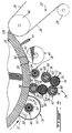
- a multicolor electrocoagulation printing apparatus comprising a central positive electrode 20 in the form of a revolving cylinder and four identical printing units 22 arranged around the cylindrical electrode 20.
- the first printing unit 22A at the left of the figure is adapted to print in yellow color
- the fourth printing unit 22D in black color is adapted to print in black color
- the cylindrical electrode 20 extends vertically and has a shaft 24 which is driven by a motor (not shown) for rotating the electrode about a vertical axis coincident with the shaft 24.
- a substrate in the form of a continuous web 26 is fed to the printing units for being imprinted with differently colored images which are transferred at respective transfer stations onto the web in superimposed relation to provide a polychromic image, the web 26 being guided to the respective transfer stations by guide rollers 28.
- the printing units 22 each comprise a cleaning device 30 for cleaning the surface 32 of the positive electrode 20, a positive electrode coating device 34 for coating the surface 32 with an olefinic substance and a metal oxide, a polishing brush 36 for polishing the olefin and metal oxide-coated surface 32, a device 38 for discharging a colloid onto the surface 32, a printing head 40 provided with negative electrodes 42 for electrocoagulating the colloid to form on the positive electrode surface 32 dots of colored, coagulated colloid representative of a desired image and a soft rubber squeegee 44 for removing any remaining non-coagulated colloid from the surface 32.
- a cleaning device 30 for cleaning the surface 32 of the positive electrode 20
- a positive electrode coating device 34 for coating the surface 32 with an olefinic substance and a metal oxide
- a polishing brush 36 for polishing the olefin and metal oxide-coated surface 32
- a device 38 for discharging a colloid onto the surface 32
- a printing head 40 provided with negative
- Each printing unit 22 further includes a pressure roller 46 for bringing the web 26 into contact with the dots of colored, coagulated colloid to cause transfer of the colored, coagulated colloid onto the web 26 and thereby imprint the web with the image.
- a pressure roller 46 for bringing the web 26 into contact with the dots of colored, coagulated colloid to cause transfer of the colored, coagulated colloid onto the web 26 and thereby imprint the web with the image.
- the positive electrode cleaning devices 30 each comprise a rotating brush 48 and two high pressure water injectors 50 arranged in a housing 52.
- Each brush 48 is provided with a plurality of radially extending bristles 54 made of horsehair and having extremities contacting the surface 32. Any coagulated colloid remaining on the surface 32 after transfer of the dots of colored, coagulated colloid at the transfer station of a preceding printing unit is thus removed by the brush 48 and washed away by the powerful jets of water produced by the injectors 50.
- the positive electrode coating devices 34 each comprise a vertically extending distribution roller 56, an applicator roller 58 extending parallel to the distribution roller 56 and in pressure contact engagement therewith to form a nip 60, and a transfer roller 62 extending parallel to the roller 56 and in contact engagement therewith to form a nip 64.
- the transfer roller 62 is in pressure contact engagement with the positive electrode 20 to form a nip 66 and permit the roller 62 to be driven by the positive electrode 20 upon rotation thereof.
- Each coating device 34 further includes a feeding device 68 for supplying to the applicator roller 58 the olefinic substance in the form of an oily dispersion containing the metal oxide as dispersed phase.
- the distribution roller 56 has a solid core 70 of metal provided with a peripheral coating 72 of oxide ceramic material.
- a pair of stub shafts 74 (only one shown) integral with the core 70 extends outwardly from the extremities of the roller 56.
- the applicator roller 58 and transfer roller 62 also have a solid core 76 of metal, but are provided with a peripheral covering 78 of polyurethane.
- the rollers 56 and 58 are rotated in register by means of a motor (not shown) driving the shaft 74 of the distribution roller 56. The drive from the motor rotates the distribution roller 56 in a counterclockwise manner, which in turn transmits a clockwise rotation to the applicator roller 58.
- the feeding device 68 is adapted to discharge the oily dispersion onto the applicator roller 58 at an upper portion thereof.
- the dispersion then flows downwardly under gravity along the roller 58 and is carried to the nip 60 by the roller 58 during rotation thereof.
- the dispersion upon passing through the nip 60 forms a film uniformly covering the surface of the ceramic coating 70 of the distribution roller 56, the film breaking down into micro-droplets containing the olefinic substance in admixture with the metal oxide and having substantially uniform size and distribution.
- the micro-droplets formed on the roller 56 are carried by the latter to the nip 64 where they are transferred onto the transfer roller 62.
- the micro-droplets are then carried by the roller 62 to the nip 66 where they are transferred onto the positive electrode 20.
- the positive electrode coating device 34' illustrated in Fig. 3 is similar to the device 34 shown in Fig. 2, except there are two distribution rollers 56 and 56' with an additional transfer roller 62' arranged therebetween. Such an arrangement ensures that the film of oily dispersion formed on the distribution roller 56 substantially completely breaks down into the desired micro-droplets prior to transfer onto the positive electrode 20, should the film only partially break down on the surface of the ceramic coating 72 of the distribution roller 56.
- the transfer roller 62' extends parallel to the distribution rollers 56 and 56' and in pressure contact engagement with the roller 56 to form a nip 80 and permit the roller 62' to be driven by the distribution roller 56 upon rotation thereof, the transfer roller 62' being in contact engagement with the distribution roller 56' to form a nip 64'.
- the distribution roller 56, applicator roller 58 and transfer roller 62' thus rotate in register.
- the second distribution roller 56' is in pressure contact engagement with the transfer roller 62 to form a nip 82 and permit the roller 56' to be driven by the transfer roller 62 upon rotation thereof.
- the distribution roller 56', transfer roller 62 and positive electrode 20 thus rotate in register.
- any partially broken film of oily dispersion formed on the surface of the ceramic coating 72 of the distribution roller 56 is transferred from the roller 56 to the transfer roller 62' at the nip 80 and thereafter transferred from the roller 62' to the distribution roller 56' at the nip 64', the film substantially completely breaking down on the surface of the ceramic coating 72 of the roller 56' into the desired micro-droplets having substantially uniform size and distribution.
- the micro-droplets of olefinic substance containing the metal oxide are then transferred from the roller 56' to the transfer roller 62 at the nip 82 and thereafter transferred from the roller 62 to the positive electrode 20 at the nip 66.
- the polishing brushes 36 used for polishing the olefin and metal oxide-coated surface 32 of the positive electrode 20 are similar to the brushes 48, each brush 36 being provided with a plurality of radially extending bristles 54 made of horsehair and having extremities contacting the surface 32.
- the friction caused by the bristles 54 contacting the surface 32 upon rotation of the brush 36 has been found to increase the adherence of the micro-droplets onto the positive electrode surface 32.
- each printing head 40 comprises a cylindrical body 84 mounted between a pair of upper and lower arms 86,86' which are pivotally connected to a column 88 with bushings 90, for pivotal movement of the printing head 40 between an operative position (shown in Figs. 1, 2 and 3) whereat the negative electrodes 42 are spaced from the positive electrode 20 by a constant predetermined gap 92 and a cleaning position (shown in Fig. 4) whereat the negative electrodes 42 are exposed to permit cleaning thereof.
- the column 88 is mounted on a horizontal beam 94 provided with a metal reinforcing member 96, the beam 94 being supported at a predetermined height by a plurality of vertical beams 98 (only one shown).
- the column 88 is fixed at its upper end to an attachment arm 100 which is connected to the shaft 24 of the electrode 20.
- a pair of collars 102,102' fixed to the column 88 support the upper and lower arms 86 and 86', respectively.
- the printing head 40 includes a pair of stub shafts 104,104' extending through the arms 86 and 86', respectively, bushings 106 being provided to enable the body 84 to be rotated about a vertical axis coincident with the shafts 104,104' and thereby permitting a greater access to the negative electrodes 42 for cleaning same.
- a releasable locking mechanism (not shown) is provided to secure the body 84 in the desired position.
- each printing head 40 is electrically insulated from one another and arranged in rectilinear alignment along the length of the body 84 to define a series of corresponding negative electrode active surfaces 108, as best shown in Fig. 5.
- the printing head 40 is positioned relative to the positive electrode 20 such that the surfaces 108 of the negative electrodes 42 are disposed in a plane parallel to the central longitudinal axis of the electrode 20 and are spaced from the positive electrode surface 32 by the gap 92.
- the electrodes 42 are also spaced from one another by a distance at least equal to the electrode gap 92 to prevent edge corrosion of the negative electrodes.
- the device 38 which is used to fill the electrode gap 92 with a colloidal dispersion containing an electrolytically coagulable colloid, a dispersing medium, a soluble electrolyte and a coloring agent comprises an elongated hollow body 110 defining a container for receiving the colloidal dispersion and a fluid discharge nozzle 112 at the lower end of the body 110 for continuously discharging the dispersion onto the positive electrode surface 32.
- the body 110 is fixed to the upper arm 86 such that when the printing head 40 is in the working position, the nozzle 112 is disposed adjacent the electrode gap 92 at a predetermined height relative to the positive electrode 20.
- colloidal dispersion As the colloidal dispersion is being discharged from the nozzle 112 onto the positive electrode surface 32, it flows downwardly along the surface 32 and is carried by the positive electrode 30 upon rotation thereof to the electrode gap 92 to fill same. Excess colloidal dispersion flowing downwardly off the surface 32 is collected in a trough 114 which is connected by conduit 116 to a reservoir 118. A recirculation pump 120 is connected to the reservoir 118 for recirculating the collected dispersion back to the device 38 through conduit 122.
- the trough 114 has an arcuate outer wall 124 adapted to be contacted by a stop member 126 fixed to the lower arm 86' when the printing head is moved to the operative position, for providing the desired electrode gap 92.
- a similar stop member 126 is fixed to the upper arm 86 for contact engagement with an abutment member (not shown) disposed above the electrode 20.
- Electrodegizing of selected ones of the negative electrodes 42 causes point-by-point selective coagulation and adherence of the colloid onto the olefin and metal oxide-coated surface 32 of the positive electrode 20 opposite the electrode active surfaces 108 of the energized negative electrodes 42 while the electrode 20 is rotating, thereby forming a series of corresponding dots of colored, coagulated colloid representative of a desired image.
- any remaining non-coagulated colloid is removed from the positive electrode surface 32 by the squeegee 44 so as to fully uncover the dots of colored, coagulated colloid adhered on the surface 32.
- Any non-coagulated colloid removed by the squeegee 44 is collected in the trough 114, mixed with excess colloidal dispersion in the reservoir 118 and the collected non-coagulated colloid in admixture with the excess colloidal dispersion is recirculated back to the device 38 by the pump 120, for discharge onto the positive electrode surface 32.
- the optical density of the dots of colored, coagulated colloid may be varied by varying the voltage and/or pulse duration of the pulse-modulated signals applied to the negative electrodes 42. Synchronisation of the data furnished to the printing heads 40 is ensured by proper electronic circuitry (not shown).
- the pressure rollers 46 which serve to bring the web 26 into contact with the dots of colored, coagulated colloid at the respective transfer stations are each in pressure contact engagement with the positive electrode 20 to form a nip 128 through which the web 26 is passed and permit the rollers 46 to be driven by the positive electrode 20 upon rotation thereof.
- the colored, coagulated colloid is transferred onto the web 26 to thereby imprint same with the image.
- the differently colored images produced by the printing units 22A, 22B, 22C and 22D are thus transferred onto the web 26 in superimposed relation to provide a polychromic image. Since a single positive electrode 20 is used and the web 26 contacts only the positive electrode surface 32 upon passing through the respective nip 128 of each transfer station, a polychromic image of high definition is obtained.
Landscapes
- Chemical & Material Sciences (AREA)
- Dispersion Chemistry (AREA)
- Engineering & Computer Science (AREA)
- Manufacturing & Machinery (AREA)
- Printing Methods (AREA)
- Ink Jet (AREA)
- Wet Developing In Electrophotography (AREA)
- Battery Electrode And Active Subsutance (AREA)
Claims (17)
- Mehrfarben-Elektrokoagulationsdruckverfahren mit den folgenden Verfahrensschritten:a) Bereitstellen einer einzelnen, positiven Elektrode (20), die aus einem elektrolytisch inaktiven Metall gebildet ist und eine kontinuierlich passivierte Oberfläche (32) aufweist, die sich mit einer im wesentlichen konstanten Geschwindigkeit entlang eines vorbestimmten Weges bewegt, wobei die passivierte Oberfläche (32) eine positive, aktive Elektrodenoberfläche definiert;b) Bilden mehrerer gefärbter, koagulierter Kolloidpunkte auf der positiven, aktiven Elektrodenoberfläche (32) mit Hilfe der Elektrokoagulation eines elektrolytisch koagulierbaren Kolloids in Anwesenheit eines Farbagenses, wobei die gefärbten, koagulierten Kolloidpunkte für ein gewünschtes Bild repräsentativ sind;c) Herstellen des Kontakts zwischen einem Substrat (26) und den gefärbten, koagulierten Kolloidpunkten, um einen Übertragung des gefärbten, koagulierten Kolloids von der positiven, aktiven Elektrodenoberfläche (32) aufdas Substrat (26) zu veranlassen, wodurch das Substrat (26) mit dem Bild bedruckt wird; undd) mehrfaches Wiederholen der Schritte b) und c), um eine entsprechende Anzahl von Druckstufen zu definieren, die in vorbestimmten Orten entlang des Weges angeordnet sind und die jeweils ein Farbagens verschiedener Farbe nutzen, wodurch mehrere verschiedenfarbiger Bilder koagulierter Kolloide erzeugt werden, die in einer überlagernden Beziehung in jeweiligen Übertragungsstellungen auf das Substrat (26) übertragen werden, so daß ein mehrfarbiges Bild entsteht.
- Verfahren nach Anspruch 1, dadurch gekennzeichnet, daß die positive Elektrode (20) als eine zylindrische Elektrode ausgebildet ist, die eine zentrale Längsachse aufweist, und die sich um die Längsachse mit im wesentlichen konstanter Geschwindigkeit dreht, und daß die Druckstufen um die positive, zylindrische Elektrode (20) herum angeordnet sind.
- Verfahren nach Anspruch 1 oder 2, wobei der Verfahrensschritt b) wie folgt ausgeführt wird:i) Bereitstellen mehrerer negativer, elektrolytisch inaktiver Elektroden (42), die von einander elektrische isoliert sind und in einer geradlinigen Ausrichtung angeordnet sind, um eine Folge entsprechender negativer, aktiver Elektrodenoberflächen (108) zu definieren, die in einer Ebene parallel zur Längsachse der positiven Elektrode (20) angeordnet sind und von der positiven, aktiven Elektrodenoberfläche mit Hilfe eines konstanten, vorbestimmten Spaltes (92) beabstandet sind, wobei die negativen Elektroden in einem Abstand voneinander angeordnet sind, derwenigstens gleich dem Elektrodenspalt (92) ist;ii) Beschichten der positiven, aktiven Elektrodenoberfläche (32) mit einer olefinischen Substanz und einem Metalloxid, um aufder Oberfläche Mikrotröpfchen der olefinischen Substanz auszubilden, die das Metalloxid enthalten;iii) Füllen des Elektrodenspaltes (42) mit einer im wesentlichen flüssigen, kolloidalen Dispersion, die das elektrolytisch koagulierbare Kolloid, das Farbagens, ein flüssiges Dispergierungsmedium und einen löslichen Elektrolyt enthält;iv) elektrisches Beaufschlagen von ausgewählten, negativen Elektroden der negativen Elektroden (42), um Punkt für Punkt eine selektive Koagulation und Haftung des Kolloids an der mit Olefin und Metalloxid beschichteten, positiven, aktiven Elektrodenoberfläche (32) zu veranlassen, die den aktiven Elektrodenoberflächen (108) der beaufschlagten negativen Elektroden (42) gegenüberliegt, wobei sich die positive Elektrode (20) hierbei dreht, wodurch die gefärbten, koagulierten Kolloidpunkte ausgebildet werden; undv) Entfernen jeglichen verbleibenden nicht koagulierten Kolloids von der positiven, aktiven Elektrodenoberfläche.
- Verfahren nach Anspruch 3, dadurch gekennzeichnet, daß der Verfahrensschritt b) ii) dadurch ausgeführt wird:daß eine Verteilerwalze (56) vorgesehen ist, die sich parallel zur positiven Elektrode (20) erstreckt und eine äußere Beschichtung (72) aufweist, die ein Oxid-Keramik-Material enthält,daß die olefinische Substanz in Form einer öligen Dispersion, die das Metalloxid in der dispergierten Phase enthält, auf die Keramikbeschichtung (72) angewendet wird, um auf einer Oberfläche der Keramikbeschichtung (72) einen Film der öligen Dispersion zu bilden, der die Oberfläche der Keramikbeschichtung (72) gleichmäßig bedeckt, wobei der Film der öligen Dispersion in Mikrotröpfchen zerfällt, die die olefinische Substanz mit einer Beimischung des Metalloxids enthalten, und die eine im wesentlichen gleichmäßige Größe und Verteilung aufweisen, unddaß die Mikrotröpfchen von der Keramikbeschichtung (72) auf die positive, aktive Elektrodenoberfläche übertragen werden.
- Verfahren nach einem der Ansprüche 1 bis 3, gekennzeichnet durch den weiteren Verfahrensschritt: Entfernen jeglichen verbleibenden koagulierten Kolloids von der positiven, aktiven Elektrodenoberfläche (32) nach Verfahrensschritt c) jeder Druckstufe.
- Mehrfarben-Elektrokoagulationsdruckvorrichtung, die Vorrichtung aufweisend:eine positive Elektrode (20), die aus einem elektrolytisch inaktiven Metall gebildet ist und eine kontinuierlich passivierte Oberfläche (32) aufweist, welche eine positive, aktive Elektrodenoberfläche definiert;Mittel zum Bewegen der positiven, aktiven Elektrodenoberfläche mit einer im wesentlichen konstanten Geschwindigkeit entlang eines vorbestimmten Weges; undmehrere Druckeinheiten (22), die in vorbestimmten Stellungen entlang des Weges angeordnet sind, jede Druckeinheit (22) aufweisend:Mittel (34, 34', 38, 42, 44) zum Ausbilden mehrerer gefärbter, koagulierter Kolloidpunkte auf der positiven, aktiven Elektrodenoberfläche mit Hilfe der Elektrokoagulation eines elektrolytisch koagulierbaren Kolloids in der Anwesenheit eines verschiedenfarbigen, gefärbten Agens, wobei die gefärbten, koagulierten Kolloidpunkte für ein gewünschtes Bild repräsentativ sind; undMittel (46), um ein Substrat (26) in einer jeweiligen Übertragungsstation mit den gefärbten, koagulierten Kolloidpunkten in Kontakt zu bringen, so daß eine Übertragung des gefärbten, koagulierten Kolloids von der positiven, aktiven Elektrodenoberfläche (32) auf das Substrat (26) veranlaßt wird, wodurch das Substrat (26) mit dem Bild bedruckt wird.
- Vorrichtung nach Anspruch 6, dadurch gekennzeichnet, daß die positive Elektrode (26) als eine zylindrische Elektrode ausgebildet ist, die eine zentrale Längsachse aufweist, und daß die Mittel zum Bewegen der positiven, aktiven Elektrodenoberfläche Mittel zum Drehen der positiven, zylindrischen Elektrode um die Längsachse umfassen, wobei die Druckeinheiten (22) um die positive, zylindrische Elektrode (32) herum angeordnet sind.
- Vorrichtung nach Anspruch 6 oder 7, die Mittel zum Ausbilden der gefärbten, koagulierten Kolloidpunkte aufweisend:mehrere negative, elektrolytisch inaktiven Elektroden (42), die voneinander elektrische isoliert sind und in einer geradlinigen Ausrichtung angeordnet sind, um eine Folge entsprechender negativer, aktiver Elektrodenoberflächen (108) zu definieren, die in einer Ebene parallel zu der Längsachse der positiven Elektrode (20) angeordnet sind und durch einen konstanten, vorbestimmten Spalt (92) von der positiven, aktiven Elektrodenoberfläche (32) beabstandet sind, wobei die negativen Elektroden (42) in einem Abstand voneinander beabstandet sind, der wenigstens gleich dem Elektrodenspalt (92) ist;Mittel (34, 34') zur Beschichtung derpositiven, aktiven Elektrodenoberfläche mit einer olefinischen Substanz und einem Metalloxid, um aufder Oberfläche (32) Mikrotröpfchen der olefinischen Substanz zu bilden, die das Metalloxid enthalten;Mittel (38) zum Füllen des Elektrodenspalts (32) mit einer im wesentlichen flüssigen, kolloidalen Dispersion die das elektrolytisch koagulierbare Kolloid, das Farbagens, ein flüssiges Dispergierungsmedium und einen löslichen Elektrolyt enthält;Mittel für elektrische Beaufschlagung ausgewählter negativer Elektroden (42), um Punkt für Punkt eine getrennte Koagulation und Haftung des Kolloids aufder mit Olefin und Metalloxid beschichteten, positiven, aktiven Elektrodenoberfläche (32) zu veranlassen, die der aktiven Elektrodenoberfläche der beaufschlagten negativen Elektroden (108) gegenüberliegt, wobei sich die positive Elektrode (20) hierbei dreht, wodurch die gefärbten, koagulierten Kolloidpunkte gebildet werden; undMittel (44) zum Entfernen jeglichen verbleibenden nicht-koagulierten Kolloids von der positiven, aktiven Elektrodenoberfläche.
- Vorrichtung nach Anspruch 8, dadurch gekennzeichnet, daß die negativen Elektroden (42) entlang der Länge eines gestreckten Kopfes (40) angeordnet sind, wobei der Kopf (40) eine Längsachse aufweist und um eine Schwenkachse geschwenkt werden kann, die sich parallel zur Längsachse des Kopfes (40) erstreckt, um die negativen Elektroden (42) zwischen einer ersten Stellung und einer zweiten Stellung zu bewegen, wobei die negativen, aktiven Elektrodenoberflächen (108) in der ersten Stellung durch den konstanten, vorbestimmten Spalt (42) von den positiven, aktiven Elektrodenoberflächen beabstandet sind, und wobei die negativen, aktiven Elektrodenoberflächen (108) in der zweiten Stellung freiliegend sind, um eine Reinigung zu ermöglichen.
- Vorrichtung nach Anspruch 8, die Mittel (34) zum Beschichten der positiven, aktiven Elektrodenoberfläche (32) aufweisend:eine Verteilerwalze (56), die sich beabstandet und parallel zu der positiven Elektrode erstreckt, wobei die Verteilerwalze eine äußere Beschichtung (72) aufweist, die ein Oxid-Keramik-Material umfaßt,Anwendungsmittel (58, 68) zum Anwenden der olefinischen Substanz in Form einer öligen Dispersion, die das Metalloxid in der dispergierten Phase enthält, auf die Keramikbeschichtung (72), um aufeiner Oberfläche der Keramikbeschichtung (72) einen Film der öligen Dispersion zu bilden, der die Oberfläche der Keramikbeschichtung (72) gleichmäßig bedeckt, wobei der Film der öligen Dispersion in Mikrotröpfchen zerfällt, die die olefinische Substanz mit einer Beimischung des Metalloxids enthalten und eine im wesentlichen gleiche Größe und Verteilung aufweisen, undÜbertragungsmittel (62), die zwischen der Verteilerwalze (56) und der positiven Elektrode (20) zur Übertragung der Mikrotröpfchen von der Keramikbeschichtung (72) auf die positive, aktive Elektrodenoberfläche (32) angeordnet sind.
- Vorrichtung nach Anspruch 8, die Mittel (34') zur Beschichtung der positiven Elektrodenoberfläche (32) aufweisend:erste und zweite Verteilerwalzen (56, 56'), die beabstandet und parallel zueinander und zu der positiven Elektrode (20) angeordnet sind, wobei die ersten und die zweiten Verteilerwalzen (56, 56') jeweils eine äußere Beschichtung (72) aufweisen, die ein Oxid-Keramik-Material enthält,Anwendungsmittel (58, 68) zum Anwenden der olefinischen Substanz in Form einer öligen Dispersion, die das Metalloxid in der dispergierten Phase enthält, auf die Keramikbeschichtung (72) der ersten Verteilerwalze (56), um aufeiner Oberfläche der ersten Verteilerwalze (56) einen Film der öligen Dispersion zu bilden, der die Oberfläche der Keramikbeschichtung (72) gleichmäßig bedeckt, wobei der Film der öligen Dispersion wenigstens teilweise in Mikrotröpfchen zerfällt, die die olefinische Substanz mit einer Beimischung des Metalloxids enthalten, und die im wesentlichen eine gleichmäßige Größe und Verteilung aufweisen,erste Übertragungsmittel (62'), die zwischen der ersten Verteilerwalze (65) und der zweiten Verteilerwalze (56') zur Übertragung des wenigstens teilweise zerfallenen Films von der ersten Verteilerwalze (56) aufdie zweite Verteilerwalze (56') so angeordnet sind, daß der Film im wesentlichen vollständig auf der Keramikbeschichtung (72) der zweiten Verteilerwalze (56') in die Mikrotröpfehen zerfällt, die eine im wesentlichen gleichmäßige Größe und Verteilung aufweisen, undzweite Übertragungsmittel (62), die zwischen der zweiten Verteilerwalze (56) und der positiven Elektrode (20) zur Übertragung der Mikrotröpfchen von der Keramikbeschichtung (72) der zweiten Verteilerrolle (56') auf die positive, aktive Elektrodenoberfläche (32) angeordnet sind.
- Vorrichtung nach Anspruch 8, wobeijede der Druckeinheiten (22) weiterhin Mittel (36) zum Polieren der mit Olefin und Metalloxid beschichteten, positiven, aktiven Elektrodenoberfläche (32) vor dem Füllen des Elektrodenspalts (92) mit der kolloidalen Dispersion umfaßt, um die Haftung der Mikrotröpfchen aufder positiven, aktiven Elektrodenoberfläche (32) zu verbessern.
- Vorrichtung nach Anspruch 8, dadurch gekennzeichnet, daß sich die positive Elektrode (20) quer erstreckt, und daß die Mittel (38) zum Füllen des Elektrodenspalts (92) mit der kolloidalen Dispersion Fluidausstoßmittel (38) umfassen, die ihr das kontinuierliche Ausstoßen der kolloidalen Dispersion aufdie positive, aktive Elektrodenoberfläche (32) benachbart zu dem Elektrodenspalt (92) und in einer vorbestimmten Höhe relativ zu der positiven Elektrode (20) angeordnet sind, wobei die kolloidale Dispersion entlang der positiven, aktiven Elektrodenoberfläche 32 abwärts fließt und mittels der positiven Elektrode (20) bei deren Drehung zu dem Elektrodenspalt (92) getragen wird, um diesen zu füllen.
- Vorrichtung nach Anspruch 6 oder 7, dadurch gekennzeichnet, daß wenigstens zwei Druckeinheiten (22) vorgesehen sind, diejeweils eine der Druckwalzen (46) umfassen, und daß die Druckwalzen (46) paarweise angeordnet sind, wobei Paare der Druckwalzen (46) diametral zueinander angeordnet sind.
- Vorrichtung nach einem der Ansprüche 6 bis 8, dadurch gekennzeichnet, daß jede der Druckeinheiten (22) Mittel (30) zum Entfernen jeglichen verbleibenden koagulierten Kolloids von der positiven, aktiven Elektrodenoberfläche (32) nach der Übertragung der gefärbten, koagulierten Kolloidpunkte auf das Substrat (26) umfaßt.
- Vorrichtung nach Anspruch 6, dadurch gekennzeichnet, daß das elektrolytische Edelmetall ein rostfreier Stahl oder Aluminium ist.
- Vorrichtung nach Anspruch 8, dadurch gekennzeichnet, daß die olefinische Substanz aus einer Gruppe ausgewählt ist, die Arachidonsäure, Ölsäure, Linolsäure, Linolensäure, Palmitoleinsäure, Maisöl, Leinsamenöl, Olivenöl, Erdnußöl, Sojabohnenöl und Sonnenblumenöl umfaßt, und daß das Metalloxid aus einer Gruppe ausgewählt ist, die Aluminiumoxid, Cerdioxid, Chromoxid, Kupferoxid, Magnesiumoxid, Maganoxid, Titandioxid und Zinkoxid umfaßt.
Applications Claiming Priority (3)
| Application Number | Priority Date | Filing Date | Title |
|---|---|---|---|
| CA2156978 | 1995-08-25 | ||
| CA002156978A CA2156978C (en) | 1995-08-25 | 1995-08-25 | Multicolor dynamic printing method and apparatus |
| PCT/JP1996/002366 WO1997007984A1 (en) | 1995-08-25 | 1996-08-26 | Multicolor dynamic printing method and apparatus |
Publications (2)
| Publication Number | Publication Date |
|---|---|
| EP0788434A1 EP0788434A1 (de) | 1997-08-13 |
| EP0788434B1 true EP0788434B1 (de) | 1999-12-22 |
Family
ID=4156493
Family Applications (1)
| Application Number | Title | Priority Date | Filing Date |
|---|---|---|---|
| EP96927891A Expired - Lifetime EP0788434B1 (de) | 1995-08-25 | 1996-08-26 | Dynamsiches vielfarbendruckverfahren und vorrichtung |
Country Status (9)
| Country | Link |
|---|---|
| EP (1) | EP0788434B1 (de) |
| JP (1) | JPH10507981A (de) |
| KR (1) | KR970706970A (de) |
| CN (1) | CN1164840A (de) |
| AU (1) | AU703802B2 (de) |
| CA (1) | CA2156978C (de) |
| DE (1) | DE69605763T2 (de) |
| NZ (1) | NZ315770A (de) |
| WO (1) | WO1997007984A1 (de) |
Family Cites Families (2)
| Publication number | Priority date | Publication date | Assignee | Title |
|---|---|---|---|---|
| US4661222A (en) * | 1986-03-27 | 1987-04-28 | Elcorsy Inc. | Monochromic and polychromic printing of an image reproduced by electro-coagulation of a colloid |
| CA1334017C (en) * | 1989-04-12 | 1995-01-17 | Adrien Castegnier | High-speed electrocoagulation printing method and apparatus |
-
1995
- 1995-08-25 CA CA002156978A patent/CA2156978C/en not_active Expired - Fee Related
-
1996
- 1996-08-26 JP JP9510112A patent/JPH10507981A/ja not_active Withdrawn
- 1996-08-26 NZ NZ315770A patent/NZ315770A/xx unknown
- 1996-08-26 EP EP96927891A patent/EP0788434B1/de not_active Expired - Lifetime
- 1996-08-26 DE DE69605763T patent/DE69605763T2/de not_active Expired - Fee Related
- 1996-08-26 KR KR1019970702742A patent/KR970706970A/ko not_active Withdrawn
- 1996-08-26 WO PCT/JP1996/002366 patent/WO1997007984A1/en not_active Ceased
- 1996-08-26 CN CN96190966A patent/CN1164840A/zh active Pending
- 1996-08-26 AU AU67545/96A patent/AU703802B2/en not_active Ceased
Also Published As
| Publication number | Publication date |
|---|---|
| CA2156978C (en) | 1998-12-15 |
| CN1164840A (zh) | 1997-11-12 |
| JPH10507981A (ja) | 1998-08-04 |
| KR970706970A (ko) | 1997-12-01 |
| WO1997007984A1 (en) | 1997-03-06 |
| CA2156978A1 (en) | 1997-02-26 |
| AU703802B2 (en) | 1999-04-01 |
| AU6754596A (en) | 1997-03-19 |
| NZ315770A (en) | 1999-02-25 |
| DE69605763D1 (de) | 2000-01-27 |
| DE69605763T2 (de) | 2000-06-15 |
| EP0788434A1 (de) | 1997-08-13 |
Similar Documents
| Publication | Publication Date | Title |
|---|---|---|
| US5538601A (en) | Electrocoagulation printing and apparatus | |
| US5908541A (en) | Multicolor electrocoagulation printing method and apparatus | |
| US5693206A (en) | Electrocoagulation printing apparatus | |
| US6045674A (en) | Intermittent electrocoagulation printing method and apparatus | |
| EP0899094B1 (de) | Mehrfarben -Elektrokoagulationsdruckverfahren und Vorrichtung | |
| EP0788434B1 (de) | Dynamsiches vielfarbendruckverfahren und vorrichtung | |
| EP1084829B1 (de) | Elektrokoagulationsdruckverfahren und Vorrichtung zur Erzeugung von erhöhter Bildauflösung | |
| US5690803A (en) | Method of enhancing transfer of coagulated colloid onto a substrate during electrocoagulation printing | |
| US5690801A (en) | Method of rendering an electrocoagulation printed image water-fast | |
| CA2214606C (en) | Method of preventing anode abrasion during electrocoagulation printing | |
| US5863402A (en) | Method of preventing anode abrasion during electrocoagulation printing | |
| US6551481B2 (en) | Electrocoagulation printing method and apparatus providing color juxtaposition | |
| CA2355458C (en) | Electrocoagulation printing method and apparatus providing color juxtaposition | |
| CA2282188C (en) | Intermittent electrocoagulation printing method and apparatus | |
| US5690802A (en) | Method of increasing coagulation efficiency during electrocoagulation printing | |
| CA2334265C (en) | Electrocoagulation printing method and apparatus providing enhanced image resolution | |
| CA2194130C (en) | Method of enhancing transfer of coagulated colloid onto a substrate during electrocoagulation printing | |
| CA2169669C (en) | Method of preventing formation of undesirable background on electrocoagulation printed images | |
| CA2194129C (en) | Method of rendering an electrocoagulation printed image water-fast | |
| EP1285748A2 (de) | Elektrokoagulationsdruckverfahren und Vorrichtung mit Farbennebeneinanderstellung | |
| US6458261B2 (en) | Electrocoagulation printing method and apparatus providing enhanced image resolution | |
| EP1348546A2 (de) | Elektrokoagulationsdruckverfahren zur Erzeugung von Bildern mit erhöhter optischer Dichte | |
| EP0845355B1 (de) | Vorrichtung zum drucken mittels elektrokoagulation | |
| EP1084827A2 (de) | Positive elektrode für den Elektrokoagulationsdruck | |
| JPWO1997047474A1 (ja) | 電気凝固印刷装置 |
Legal Events
| Date | Code | Title | Description |
|---|---|---|---|
| PUAI | Public reference made under article 153(3) epc to a published international application that has entered the european phase |
Free format text: ORIGINAL CODE: 0009012 |
|
| 17P | Request for examination filed |
Effective date: 19970520 |
|
| AK | Designated contracting states |
Kind code of ref document: A1 Designated state(s): DE FR GB IT |
|
| 17Q | First examination report despatched |
Effective date: 19981113 |
|
| GRAG | Despatch of communication of intention to grant |
Free format text: ORIGINAL CODE: EPIDOS AGRA |
|
| GRAG | Despatch of communication of intention to grant |
Free format text: ORIGINAL CODE: EPIDOS AGRA |
|
| GRAH | Despatch of communication of intention to grant a patent |
Free format text: ORIGINAL CODE: EPIDOS IGRA |
|
| GRAH | Despatch of communication of intention to grant a patent |
Free format text: ORIGINAL CODE: EPIDOS IGRA |
|
| GRAA | (expected) grant |
Free format text: ORIGINAL CODE: 0009210 |
|
| AK | Designated contracting states |
Kind code of ref document: B1 Designated state(s): DE FR GB IT |
|
| REF | Corresponds to: |
Ref document number: 69605763 Country of ref document: DE Date of ref document: 20000127 |
|
| ITF | It: translation for a ep patent filed | ||
| ET | Fr: translation filed | ||
| PLBE | No opposition filed within time limit |
Free format text: ORIGINAL CODE: 0009261 |
|
| STAA | Information on the status of an ep patent application or granted ep patent |
Free format text: STATUS: NO OPPOSITION FILED WITHIN TIME LIMIT |
|
| 26N | No opposition filed | ||
| REG | Reference to a national code |
Ref country code: GB Ref legal event code: IF02 |
|
| PGFP | Annual fee paid to national office [announced via postgrant information from national office to epo] |
Ref country code: FR Payment date: 20030808 Year of fee payment: 8 |
|
| PGFP | Annual fee paid to national office [announced via postgrant information from national office to epo] |
Ref country code: GB Payment date: 20030820 Year of fee payment: 8 |
|
| PGFP | Annual fee paid to national office [announced via postgrant information from national office to epo] |
Ref country code: DE Payment date: 20030904 Year of fee payment: 8 |
|
| PG25 | Lapsed in a contracting state [announced via postgrant information from national office to epo] |
Ref country code: GB Free format text: LAPSE BECAUSE OF NON-PAYMENT OF DUE FEES Effective date: 20040826 |
|
| PG25 | Lapsed in a contracting state [announced via postgrant information from national office to epo] |
Ref country code: DE Free format text: LAPSE BECAUSE OF NON-PAYMENT OF DUE FEES Effective date: 20050301 |
|
| GBPC | Gb: european patent ceased through non-payment of renewal fee |
Effective date: 20040826 |
|
| PG25 | Lapsed in a contracting state [announced via postgrant information from national office to epo] |
Ref country code: FR Free format text: LAPSE BECAUSE OF NON-PAYMENT OF DUE FEES Effective date: 20050429 |
|
| REG | Reference to a national code |
Ref country code: FR Ref legal event code: ST |
|
| PG25 | Lapsed in a contracting state [announced via postgrant information from national office to epo] |
Ref country code: IT Free format text: LAPSE BECAUSE OF NON-PAYMENT OF DUE FEES;WARNING: LAPSES OF ITALIAN PATENTS WITH EFFECTIVE DATE BEFORE 2007 MAY HAVE OCCURRED AT ANY TIME BEFORE 2007. THE CORRECT EFFECTIVE DATE MAY BE DIFFERENT FROM THE ONE RECORDED. Effective date: 20050826 |