EP0788558B1 - Method and apparatus for adding aluminum and calcium to molten lead - Google Patents
Method and apparatus for adding aluminum and calcium to molten lead Download PDFInfo
- Publication number
- EP0788558B1 EP0788558B1 EP95931106A EP95931106A EP0788558B1 EP 0788558 B1 EP0788558 B1 EP 0788558B1 EP 95931106 A EP95931106 A EP 95931106A EP 95931106 A EP95931106 A EP 95931106A EP 0788558 B1 EP0788558 B1 EP 0788558B1
- Authority
- EP
- European Patent Office
- Prior art keywords
- housing
- lead
- calcium
- impeller
- aluminum
- Prior art date
- Legal status (The legal status is an assumption and is not a legal conclusion. Google has not performed a legal analysis and makes no representation as to the accuracy of the status listed.)
- Expired - Lifetime
Links
- XAGFODPZIPBFFR-UHFFFAOYSA-N aluminium Chemical compound [Al] XAGFODPZIPBFFR-UHFFFAOYSA-N 0.000 title claims abstract description 124
- 239000011575 calcium Substances 0.000 title claims abstract description 120
- 229910052791 calcium Inorganic materials 0.000 title claims abstract description 116
- OYPRJOBELJOOCE-UHFFFAOYSA-N Calcium Chemical compound [Ca] OYPRJOBELJOOCE-UHFFFAOYSA-N 0.000 title claims abstract description 112
- 229910052782 aluminium Inorganic materials 0.000 title claims abstract description 105
- 238000000034 method Methods 0.000 title claims abstract description 34
- 239000002245 particle Substances 0.000 claims abstract description 54
- 229910045601 alloy Inorganic materials 0.000 claims abstract description 16
- 239000000956 alloy Substances 0.000 claims abstract description 16
- 230000008569 process Effects 0.000 claims abstract description 13
- 239000002142 lead-calcium alloy Substances 0.000 claims abstract description 9
- 239000000463 material Substances 0.000 claims description 4
- HCHKCACWOHOZIP-UHFFFAOYSA-N Zinc Chemical compound [Zn] HCHKCACWOHOZIP-UHFFFAOYSA-N 0.000 claims 1
- 229910052725 zinc Inorganic materials 0.000 claims 1
- 239000011701 zinc Substances 0.000 claims 1
- 238000011084 recovery Methods 0.000 description 51
- 238000007792 addition Methods 0.000 description 26
- 238000004090 dissolution Methods 0.000 description 22
- 239000002184 metal Substances 0.000 description 21
- 229910052751 metal Inorganic materials 0.000 description 20
- 239000003153 chemical reaction reagent Substances 0.000 description 16
- 238000013461 design Methods 0.000 description 12
- 239000007788 liquid Substances 0.000 description 10
- 239000002923 metal particle Substances 0.000 description 10
- 239000007787 solid Substances 0.000 description 10
- 238000006243 chemical reaction Methods 0.000 description 9
- 230000003647 oxidation Effects 0.000 description 8
- 238000007254 oxidation reaction Methods 0.000 description 8
- 238000012360 testing method Methods 0.000 description 8
- 238000002474 experimental method Methods 0.000 description 7
- 229910000978 Pb alloy Inorganic materials 0.000 description 6
- 239000011261 inert gas Substances 0.000 description 6
- 230000014759 maintenance of location Effects 0.000 description 6
- 239000000155 melt Substances 0.000 description 6
- 230000008018 melting Effects 0.000 description 6
- 238000002844 melting Methods 0.000 description 6
- 238000012545 processing Methods 0.000 description 6
- -1 calcium-aluminum-lead Chemical compound 0.000 description 5
- 230000001681 protective effect Effects 0.000 description 5
- 239000006023 eutectic alloy Substances 0.000 description 4
- 239000007789 gas Substances 0.000 description 4
- 229910000464 lead oxide Inorganic materials 0.000 description 4
- YEXPOXQUZXUXJW-UHFFFAOYSA-N oxolead Chemical compound [Pb]=O YEXPOXQUZXUXJW-UHFFFAOYSA-N 0.000 description 4
- 238000003756 stirring Methods 0.000 description 4
- 229910000882 Ca alloy Inorganic materials 0.000 description 3
- 238000004458 analytical method Methods 0.000 description 3
- 238000005516 engineering process Methods 0.000 description 3
- 238000007667 floating Methods 0.000 description 3
- 239000003517 fume Substances 0.000 description 3
- 239000000203 mixture Substances 0.000 description 3
- 239000000843 powder Substances 0.000 description 3
- XLYOFNOQVPJJNP-UHFFFAOYSA-N water Substances O XLYOFNOQVPJJNP-UHFFFAOYSA-N 0.000 description 3
- 229910000838 Al alloy Inorganic materials 0.000 description 2
- XKRFYHLGVUSROY-UHFFFAOYSA-N Argon Chemical compound [Ar] XKRFYHLGVUSROY-UHFFFAOYSA-N 0.000 description 2
- UFHFLCQGNIYNRP-UHFFFAOYSA-N Hydrogen Chemical compound [H][H] UFHFLCQGNIYNRP-UHFFFAOYSA-N 0.000 description 2
- 239000002253 acid Substances 0.000 description 2
- 238000005275 alloying Methods 0.000 description 2
- 230000001419 dependent effect Effects 0.000 description 2
- 230000007613 environmental effect Effects 0.000 description 2
- 230000006872 improvement Effects 0.000 description 2
- 238000012423 maintenance Methods 0.000 description 2
- 239000000126 substance Substances 0.000 description 2
- 238000012935 Averaging Methods 0.000 description 1
- 239000004484 Briquette Substances 0.000 description 1
- 239000005997 Calcium carbide Substances 0.000 description 1
- 229910001245 Sb alloy Inorganic materials 0.000 description 1
- ULGYAEQHFNJYML-UHFFFAOYSA-N [AlH3].[Ca] Chemical compound [AlH3].[Ca] ULGYAEQHFNJYML-UHFFFAOYSA-N 0.000 description 1
- PRSMTOHTFYVJSQ-UHFFFAOYSA-N [Ca].[Pb] Chemical compound [Ca].[Pb] PRSMTOHTFYVJSQ-UHFFFAOYSA-N 0.000 description 1
- AZDRQVAHHNSJOQ-UHFFFAOYSA-N alumane Chemical group [AlH3] AZDRQVAHHNSJOQ-UHFFFAOYSA-N 0.000 description 1
- 229910052787 antimony Inorganic materials 0.000 description 1
- 239000002140 antimony alloy Substances 0.000 description 1
- 229910052786 argon Inorganic materials 0.000 description 1
- QVGXLLKOCUKJST-UHFFFAOYSA-N atomic oxygen Chemical compound [O] QVGXLLKOCUKJST-UHFFFAOYSA-N 0.000 description 1
- 230000008901 benefit Effects 0.000 description 1
- 230000008859 change Effects 0.000 description 1
- 230000002301 combined effect Effects 0.000 description 1
- 238000011161 development Methods 0.000 description 1
- 238000003487 electrochemical reaction Methods 0.000 description 1
- 239000003792 electrolyte Substances 0.000 description 1
- 230000005496 eutectics Effects 0.000 description 1
- 239000012530 fluid Substances 0.000 description 1
- 210000004907 gland Anatomy 0.000 description 1
- 239000008187 granular material Substances 0.000 description 1
- 230000036541 health Effects 0.000 description 1
- 238000002347 injection Methods 0.000 description 1
- 239000007924 injection Substances 0.000 description 1
- 229910001338 liquidmetal Inorganic materials 0.000 description 1
- 238000004519 manufacturing process Methods 0.000 description 1
- 239000000320 mechanical mixture Substances 0.000 description 1
- 229910001092 metal group alloy Inorganic materials 0.000 description 1
- 150000002739 metals Chemical class 0.000 description 1
- 238000012986 modification Methods 0.000 description 1
- 230000004048 modification Effects 0.000 description 1
- 239000001301 oxygen Substances 0.000 description 1
- 229910052760 oxygen Inorganic materials 0.000 description 1
- 230000000737 periodic effect Effects 0.000 description 1
- 230000001737 promoting effect Effects 0.000 description 1
- 230000000717 retained effect Effects 0.000 description 1
- 230000000630 rising effect Effects 0.000 description 1
- 239000000243 solution Substances 0.000 description 1
- CLZWAWBPWVRRGI-UHFFFAOYSA-N tert-butyl 2-[2-[2-[2-[bis[2-[(2-methylpropan-2-yl)oxy]-2-oxoethyl]amino]-5-bromophenoxy]ethoxy]-4-methyl-n-[2-[(2-methylpropan-2-yl)oxy]-2-oxoethyl]anilino]acetate Chemical compound CC1=CC=C(N(CC(=O)OC(C)(C)C)CC(=O)OC(C)(C)C)C(OCCOC=2C(=CC=C(Br)C=2)N(CC(=O)OC(C)(C)C)CC(=O)OC(C)(C)C)=C1 CLZWAWBPWVRRGI-UHFFFAOYSA-N 0.000 description 1
- 238000013022 venting Methods 0.000 description 1
Images

Classifications
-
- C—CHEMISTRY; METALLURGY
- C22—METALLURGY; FERROUS OR NON-FERROUS ALLOYS; TREATMENT OF ALLOYS OR NON-FERROUS METALS
- C22C—ALLOYS
- C22C1/00—Making non-ferrous alloys
- C22C1/02—Making non-ferrous alloys by melting
-
- B—PERFORMING OPERATIONS; TRANSPORTING
- B01—PHYSICAL OR CHEMICAL PROCESSES OR APPARATUS IN GENERAL
- B01F—MIXING, e.g. DISSOLVING, EMULSIFYING OR DISPERSING
- B01F23/00—Mixing according to the phases to be mixed, e.g. dispersing or emulsifying
- B01F23/50—Mixing liquids with solids
- B01F23/51—Methods thereof
- B01F23/511—Methods thereof characterised by the composition of the liquids or solids
-
- B—PERFORMING OPERATIONS; TRANSPORTING
- B01—PHYSICAL OR CHEMICAL PROCESSES OR APPARATUS IN GENERAL
- B01F—MIXING, e.g. DISSOLVING, EMULSIFYING OR DISPERSING
- B01F27/00—Mixers with rotary stirring devices in fixed receptacles; Kneaders
- B01F27/80—Mixers with rotary stirring devices in fixed receptacles; Kneaders with stirrers rotating about a substantially vertical axis
- B01F27/91—Mixers with rotary stirring devices in fixed receptacles; Kneaders with stirrers rotating about a substantially vertical axis with propellers
-
- B—PERFORMING OPERATIONS; TRANSPORTING
- B01—PHYSICAL OR CHEMICAL PROCESSES OR APPARATUS IN GENERAL
- B01F—MIXING, e.g. DISSOLVING, EMULSIFYING OR DISPERSING
- B01F27/00—Mixers with rotary stirring devices in fixed receptacles; Kneaders
- B01F27/05—Stirrers
- B01F27/11—Stirrers characterised by the configuration of the stirrers
- B01F27/15—Stirrers with tubes for guiding the material
Definitions
- This invention relates to a method for simultaneous addition of aluminum and calcium and alloys thereof to molten lead for the production of lead-calcium alloys.
- lead-calcium alloy grids were developed since these alloys greatly reduce the amount of hydrogen gas generated by the electrochemical reaction. As little as 0.1% calcium in the lead alloy is sufficient to reduce gassing to a level where the battery can virtually be sealed and no water additions are required.
- calcium may be introduced by adding calcium carbide as in U.S. Patent No. 1,941,534 to Betterton, which issued January 2, 1934.
- the metallurgical difficulty with producing lead-calcium alloys is not in general related to the addition of calcium to molten lead since, as discussed above, there are several alternative alloying methods.
- the major problems relate to the fade of calcium once it has been dissolved in the liquid lead pool.
- Lead-calcium alloys are very prone to the loss of calcium due to oxidation at the melt surface where reactive calcium dissolved in the molten lead comes in contact with oxygen in atmospheric air.
- a solution to the problems associated with calcium fade is given by the addition of minor amounts of aluminum (0.005% to 0.05%) to the lead-calcium alloy.
- Aluminum forms a tenacious oxide layer on the surface of the lead alloy melt thereby minimizing the oxidation of calcium.
- the molten lead temperature has to be raised above aluminum's melting point (660°C) which is considerably higher than the normal range for lead processing. Due to its reactive nature, calcium metal is usually added at about 420°C. Hence there is an incompatibility between the melt temperatures at which solid aluminum and calcium metals can be added. Alternatively, pre-melted liquid aluminum can be poured and stirred into the lead bath; however, this requires a second furnace to melt the aluminum.
- the eutectic alloy allows for simultaneous addition of calcium and aluminum in a ratio of approximately 3 Ca:1 Al at molten lead temperatures of about 570°C.
- reagent recoveries with this alloy are higher than for the pure calcium and aluminum metal addition practices outlined above; calcium and aluminum recoveries of 90% and 70% respectively can be expected with the alloy.
- the major difficulty arising with the use of this alloy is, however, that the addition ratio is 3 Ca:1 Al which often does not correspond to the proportion of calcium and aluminum required by the lead alloy specifications.
- the desired Ca:Al ratio in the final lead alloy can be as high as 10:1.
- U.S. Patent 4,627,961 issued December 9, 1986 to Dudek, calls for the simultaneous addition of calcium and aluminum by compressing a mechanical mixture of the respective metal granules into a briquette. The briquettes are then added into a vortex created by stirring molten lead at temperatures between 550 and 600°C. The major difficulty with this method is unpredictability in the amount of calcium and aluminum recovered in the melt. Trials with calcium/aluminum briquettes, described in column 1 of aforesaid U.S. Patent No. 4,808,376, show highly variable results with calcium recoveries varying by up to 10% and aluminum recoveries varying by over 34%.
- the present invention utilizes a simple system for simultaneous addition of calcium and aluminum metals at normal lead processing temperatures (typically 560°C and in any event below 660°C) with high and predictable recoveries and minimal oxidation and fume emissions.
- the present invention makes use of the exothermic release of heat provided when calcium metal dissolves in molten lead.
- the heat release associated with calcium dissolution will cause a sharp local increase in the temperature of the lead surrounding the dissolving calcium particles. Since high melt temperatures are required to dissolve aluminum in lead, any aluminum particles coming in contact with the locally superheated lead adjacent to a calcium particle will dissolve rapidly.
- the temperature of the lead bath will normally be less than 660°C.
- a further aspect of the invention is an apparatus for introducing calcium and aluminum into a bath of molten lead as specified in claim 5 or 8.
- proper swirling of the lead is partially dependent on the shape of the housing and partially dependent on the nature and position of the impeller.
- the housing is constricted to impede flow of lead through the bottom opening and to assist in recirculation.
- the lower portion of the tubular housing converges downwardly, providing a conical constriction leading to an outlet opening which may be about one half the maximum diameter of the housing and may be less than the impeller diameter. This helps to promote radial liquid flow to ensure that the calcium and aluminum particles are held in the tubular housing for an adequate length of time.
- the design and location of the impeller is critical to establishing optimum liquid flow patterns inside the tubular housing.
- the impeller is located inside the housing just above the bottom opening, or at least closer to the bottom outlet than to a mid point of the downwardly converging portion.
- the conical constriction in the bottom portion of the tubular housing is extremely important since it restricts the flow of lead through the bottom opening and thereby promotes radial flow. Without this constriction in the diameter of the tubular housing, the vortex would favour more axial flow thereby enabling calcium and particularly aluminum solid particles to escape the housing before being completely dissolved into the lead.
- the impeller is located near the point of constriction inside the tubular housing.
- flow inside the housing reverses with liquid lead from the bulk melt being drawn in through the bottom opening and passing out of the top openings.
- the canopy above the top openings ensures that any unreacted calcium and aluminum particles which may be inadvertently discharged through the top openings are caught in the canopy because of their high buoyancy relative to lead and are thereby prevented from floating to the surface of the lead bath where they would be lost as unreacted reagent.
- the rotary impeller used in both embodiments herein is preferably at least partially of the centrifugal type, so that the lead in the region of the impeller is caused to move both radially and axially and to strike the walls of the tubular housing, and to swirl around adjacent to the wall before leaving the outlet.
- the tubular housing is constricted in diameter so as to decrease axial flow and promote more radial flow within the housing. This is an important aspect of the present invention since it increases residence time of the aluminum and calcium particles inside the tubular housing.
- Fig. 1 shows the essential elements of prior art U.S. Patent No. 3,741,754 used for adding reactive metal, such as calcium, to molten lead while using a protective gas covering provided by an inert gas.
- a supply chute 12 forming the lower end of a feed hopper is used to deliver a supply of the reactive material.
- a cylindrical housing 16 which is closed at its top end 17 and open at its bottom end 18 is supported by support arm 20 from a movable frame 24.
- An inner chamber 26 is centrally disposed within housing 16. Within chamber 26 is located an impeller 28 of the marine or axial flow type attached to rotary shaft 29, which shaft extends up through gland 30 and has its upper end driven by a motor/gear box combination also mounted on frame 24.
- a vibrator 31 is connected to the base of chute 12 to assist flow of the reactive metal into the lead bath 32.
- An inert gas stream is provided through supply conduit 33; this assists movement of reactive particles into the top of housing 16.
- Frame 24 is arranged to be movable over a molten metal bath to be treated.
- the frame 24 is positioned to insert part of housing 16 and all of inner chamber 26 below the surface 32 of the molten lead.
- Inert gas is supplied through conduit 33, and the lead temperature adjusted to 900 to 950°F (i.e. 482 to 510°C).
- Calcium particles are supplied at a rate of about 115 grams per second (about 15 pounds per minute), while the impeller 28 is rotated at about 280 rpm to produce a deep vortex in the bath.
- the impeller tends to pull liquid lead upwardly through the annular space between the housing 16 and the inner chamber 26 and then downwardly through the chamber and out through its bottom outlet into the bath.
- the calcium particles are mixed with the molten lead during this movement.
- calcium-lead alloys were reportedly made ranging in calcium content from about 0.025% to 1.5% by weight calcium, based on the combined weight of calcium and lead in the alloy.
- the prior patent also reported that the addition of 6 mesh calcium nodules at a rate of about 115 grams per second (about 15 pounds per minute) to a lead bath at 480-510°C produced calcium recovery of about 88% by weight, i.e. about 88% of all calcium input became a part of the calcium-lead alloy.
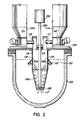
- Fig. 2 shows the preferred embodiment of apparatus in accordance with the invention which has been found to overcome the shortcomings of the prior art apparatus of Fig. 1.
- two supply chutes 111 and 112 are provided from two separate hoppers 111a and 112a for calcium and aluminum particles or for calcium/aluminum alloy particles. These chutes pass into the otherwise closed top 113 of tubular housing 116 having an open bottom end outlet 117.
- the chutes can, if required, also be used for the introduction of a protective inert gas into the top of the housing.
- the housing and chutes are carried by a frame part 124 which can be moved into place as required over a vessel 125 containing the molten lead, the upper surface of which is indicated at 132.
- the closed top 113 accommodates drive shaft 129 of motor 130 which carries impeller 128 at its lower end.
- the housing 116 has a series of slots 118 around its periphery, which provide inlet means located at relatively small depth below the surface 132 of the lead; i.e. a depth which is small relative to that of the bottom outlet 117.
- a downwardly diverging frusto-conical deflector or canopy 119 is fixed to the outer surface of the housing 116 just above the slots 118; this ensures that melt entering the slots is not contaminated with surface dross or the like.
- the impeller 128 and the design of the housing 116 lie in the nature of the impeller 128 and the design of the housing 116.
- the impeller instead of being a marine or axial flow type propeller, as shown in the '754 patent, is at least partially of the centrifugal flow type.
- the blades of the impeller are set at an angle of between 40° and 50° to the horizontal impeller plane, preferably about 45°; rather than the shallower angle usual with axial flow type impellers.
- Applicants' impeller provides both substantial radial flow as well as axial flow; axial flow ensures that lead is moved through the housing while centrifugal flow ensures that it is swirled around in the housing long enough to become alloyed with the calcium and aluminum.
- an impeller of this kind may be termed a modified turbine impeller.
- the axial flow impeller in the '754 patent was more than two thirds the internal diameter of the housing, in the present invention the impeller diameter is less than one-half the diameter of the cylindrical portion of the housing 116 and is preferably slightly smaller than the diameter of the bottom outlet.
- the housing is wholly cylindrical in shape, applicants' housing 116 is cylindrical in the upper portion and constricted by a frusto-conical lower section 116a.
- the turbine impeller in combination with the frusto-conical constriction create a vortex with sufficient radial flow such that particles of the feed metals are caused to swirl around within the housing between the wall and the impeller, and above the impeller, and this ensures close proximity of the calcium and aluminum particles and maximizes their retention time within the housing.
- the exothermic reaction between the calcium and the lead heats the lead within the housing and adjacent to the particles and this causes dissolving of the aluminum.
- protective gas if desired can be introduced into the housing through chutes 111 and 112 or by a separate inlet port. While the use of a protective gas is not essential, tests show that use of an inert gas such as argon will improve calcium recovery by as much as 15 to 20%.
- a conical housing similar to that shown in Fig. 2 was inserted into a 1250 kg molten lead bath.
- the lead melt was initially maintained at 560°C. 1.45 kg of calcium metal particles and 0.21 kg of aluminum metal particles were added simultaneously to the lead vortex generated with the impeller operating at 600 rpm inside the conical reaction housing.
- the reagents were introduced into the melt over a 7 to 8 minute time interval. Stirring inside the housing continued for up to 20 minutes from the start of reagent feeding. Samples were taken for chemical spectrographic analysis from the bulk lead pool outside the housing at 0, 5, 10 and 20 minute intervals from the start of reagent feeding. The results below indicate that, with the housing and impeller combination with this preferred embodiment, calcium recovery reached 92.7% by 10 minutes and 96.1% after 20 minutes. Aluminum recovery is exceptionally high reaching 81.6% at 10 minutes and increased to 82.7% after 20 minutes.
- Example 2 The exact same experiment as described in Example 1 was repeated to confirm calcium and aluminum particle dissolution and recovery with the apparatus of this invention as described. Once again, dissolution was complete at the 10 minute mark, that is within 2 to 3 minutes after the end of reagent feeding. Final calcium analyzed at 1050 ppm (92.3% recovery) and the aluminum analyzed at 165 ppm (98.2% recovery).
- FIG. 3 A second embodiment of this invention as shown in Fig. 3, in which the same reference numerals are used for parts which are the same as those of Fig. 2.
- the Fig. 3 arrangement allows for the turbine impeller 228 to be located approximately at the elevation where the cylindrical portion of the housing meets the constricted portion 216a.
- the impeller design and the frusto-conical lower section of the housing promote combined axial and radial flow patterns as shown by the arrows in Fig. 3. In this case, however, it has been found that raising the position of the impeller results in a reversal of the metal flow with liquid lead flowing in through the bottom opening and out the top openings.
- rotating impeller 228 at sufficient speed e.g.
- a conical housing similar to that shown in Fig. 3 was inserted into a 1250 kg molten lead bath.
- the lead melt was initially maintained at 560°C. 1.48 kg of calcium metal particles and 0.21 kg of aluminum metal particles were added simultaneously to the lead vortex generated with the impeller operating at 600 rpm inside the conical reaction housing.
- the reagents were introduced into the melt over a 7 to 8 minute time interval. Stirring inside the housing continued for up to 20 minutes from the start of reagent feeding. Samples were taken for chemical spectrographic analysis from the bulk lead pool outside the housing at 0, 5, 10 and 20 minute intervals from the start of reagent feeding.
- the 40 ppm increase in calcium levels between 10 and 20 minutes is considered insignificant; hence dissolution with the housing was complete at 10 minutes, that is within 2 to 3 minutes after end of reagent feeding.
Landscapes
- Chemical & Material Sciences (AREA)
- Chemical Kinetics & Catalysis (AREA)
- Engineering & Computer Science (AREA)
- Materials Engineering (AREA)
- Mechanical Engineering (AREA)
- Metallurgy (AREA)
- Organic Chemistry (AREA)
- Dispersion Chemistry (AREA)
- Manufacture And Refinement Of Metals (AREA)
- Manufacture Of Metal Powder And Suspensions Thereof (AREA)
- Cell Electrode Carriers And Collectors (AREA)
- Mixers Of The Rotary Stirring Type (AREA)
Applications Claiming Priority (3)
| Application Number | Priority Date | Filing Date | Title |
|---|---|---|---|
| CA002132485A CA2132485A1 (en) | 1994-05-09 | 1994-09-20 | Method and apparatus for adding aluminum and calcium to molten lead |
| CA2132485 | 1994-09-20 | ||
| PCT/CA1995/000525 WO1996009418A1 (en) | 1994-09-20 | 1995-09-19 | Method and apparatus for adding aluminum and calcium to molten lead |
Publications (2)
| Publication Number | Publication Date |
|---|---|
| EP0788558A1 EP0788558A1 (en) | 1997-08-13 |
| EP0788558B1 true EP0788558B1 (en) | 1999-02-10 |
Family
ID=4154364
Family Applications (1)
| Application Number | Title | Priority Date | Filing Date |
|---|---|---|---|
| EP95931106A Expired - Lifetime EP0788558B1 (en) | 1994-09-20 | 1995-09-19 | Method and apparatus for adding aluminum and calcium to molten lead |
Country Status (13)
| Country | Link |
|---|---|
| EP (1) | EP0788558B1 (cs) |
| JP (1) | JPH10505880A (cs) |
| AT (1) | ATE176688T1 (cs) |
| AU (1) | AU687636B2 (cs) |
| BR (1) | BR9508848A (cs) |
| CZ (1) | CZ82697A3 (cs) |
| DE (1) | DE69507831T2 (cs) |
| DK (1) | DK0788558T3 (cs) |
| ES (1) | ES2128759T3 (cs) |
| GR (1) | GR3029968T3 (cs) |
| NO (1) | NO971138D0 (cs) |
| NZ (1) | NZ292491A (cs) |
| WO (1) | WO1996009418A1 (cs) |
Family Cites Families (3)
| Publication number | Priority date | Publication date | Assignee | Title |
|---|---|---|---|---|
| US1386503A (en) * | 1921-08-02 | And milo w | ||
| US3741754A (en) * | 1971-04-29 | 1973-06-26 | States Smelting Refining & Min | Method for making metal alloys |
| US4439398A (en) * | 1981-11-13 | 1984-03-27 | Rsr Corporation | Method of alloying calcium and aluminum into lead |
-
1995
- 1995-09-19 DK DK95931106T patent/DK0788558T3/da active
- 1995-09-19 DE DE69507831T patent/DE69507831T2/de not_active Expired - Fee Related
- 1995-09-19 CZ CZ97826A patent/CZ82697A3/cs unknown
- 1995-09-19 AT AT95931106T patent/ATE176688T1/de active
- 1995-09-19 ES ES95931106T patent/ES2128759T3/es not_active Expired - Lifetime
- 1995-09-19 EP EP95931106A patent/EP0788558B1/en not_active Expired - Lifetime
- 1995-09-19 AU AU34678/95A patent/AU687636B2/en not_active Ceased
- 1995-09-19 BR BR9508848-2A patent/BR9508848A/pt not_active Application Discontinuation
- 1995-09-19 NZ NZ292491A patent/NZ292491A/en unknown
- 1995-09-19 WO PCT/CA1995/000525 patent/WO1996009418A1/en not_active Ceased
- 1995-09-19 JP JP8510478A patent/JPH10505880A/ja active Pending
-
1997
- 1997-03-12 NO NO971138A patent/NO971138D0/no not_active Application Discontinuation
-
1999
- 1999-04-16 GR GR990401047T patent/GR3029968T3/el unknown
Also Published As
| Publication number | Publication date |
|---|---|
| DE69507831D1 (de) | 1999-03-25 |
| DK0788558T3 (da) | 1999-09-20 |
| ATE176688T1 (de) | 1999-02-15 |
| DE69507831T2 (de) | 1999-08-19 |
| JPH10505880A (ja) | 1998-06-09 |
| BR9508848A (pt) | 2002-04-16 |
| WO1996009418A1 (en) | 1996-03-28 |
| EP0788558A1 (en) | 1997-08-13 |
| AU3467895A (en) | 1996-04-09 |
| AU687636B2 (en) | 1998-02-26 |
| ES2128759T3 (es) | 1999-05-16 |
| NZ292491A (en) | 1997-06-24 |
| CZ82697A3 (en) | 1997-12-17 |
| GR3029968T3 (en) | 1999-07-30 |
| NO971138L (no) | 1997-03-12 |
| NO971138D0 (no) | 1997-03-12 |
Similar Documents
| Publication | Publication Date | Title |
|---|---|---|
| JP4341985B2 (ja) | 金属および金属合金を製造する方法 | |
| US3792848A (en) | Device for improving reactions between two components of a metallurgical melt | |
| US4618427A (en) | Method of treating and breaking up a liquid with the help of centripetal force | |
| JPH0765126B2 (ja) | 溶融金属処理装置および処理方法 | |
| HK27686A (en) | Stirring equipment for the dispersion of gas during the treatment of metal baths | |
| EP0392900B1 (fr) | Procédé et installation de traitement d'un liquide avec un gaz | |
| KR20010079741A (ko) | 직접 제련 방법 | |
| AU747623B2 (en) | Injector for gas treatment of molten metals | |
| EP0556343B1 (en) | Jet flow device for injecting gas into molten metal | |
| JP2005068506A (ja) | 溶銑の脱硫方法及び脱硫装置 | |
| EP1462530A1 (en) | Apparatus for refining molten metal and method for refining molten metal using the same | |
| US2786755A (en) | Method and apparatus for alloying magnesium | |
| US5547634A (en) | Method for adding aluminum and calcium to molten lead | |
| EP0788558B1 (en) | Method and apparatus for adding aluminum and calcium to molten lead | |
| JP2003119509A (ja) | 溶銑予備処理方法及びインペラー装置 | |
| CA1110078A (en) | Method and apparatus for the refining of melts by means of a pulverous solid material and/or a gas | |
| CA2132485A1 (en) | Method and apparatus for adding aluminum and calcium to molten lead | |
| US4240618A (en) | Stirrer for metallurgical melts | |
| EP4006471A1 (en) | Metal melting device, screen plate for melting metal, and method for melting metal | |
| US3741754A (en) | Method for making metal alloys | |
| US4605438A (en) | Apparatus and method for forming a wear-resistant metal composition | |
| CN222567754U (zh) | 电池粉浸出反应装置 | |
| JPH07113131B2 (ja) | Al又はAl合金溶湯の脱ガス法及びその装置 | |
| JP2007204843A (ja) | ガス吹込みノズル装置およびそれを備えたガス吹込み設備 | |
| USRE27548E (en) | Spitz etal method op repining copper |
Legal Events
| Date | Code | Title | Description |
|---|---|---|---|
| PUAI | Public reference made under article 153(3) epc to a published international application that has entered the european phase |
Free format text: ORIGINAL CODE: 0009012 |
|
| 17P | Request for examination filed |
Effective date: 19970303 |
|
| AK | Designated contracting states |
Kind code of ref document: A1 Designated state(s): AT BE CH DE DK ES FR GB GR IE IT LI NL SE |
|
| 17Q | First examination report despatched |
Effective date: 19970902 |
|
| GRAG | Despatch of communication of intention to grant |
Free format text: ORIGINAL CODE: EPIDOS AGRA |
|
| GRAG | Despatch of communication of intention to grant |
Free format text: ORIGINAL CODE: EPIDOS AGRA |
|
| GRAH | Despatch of communication of intention to grant a patent |
Free format text: ORIGINAL CODE: EPIDOS IGRA |
|
| GRAH | Despatch of communication of intention to grant a patent |
Free format text: ORIGINAL CODE: EPIDOS IGRA |
|
| GRAA | (expected) grant |
Free format text: ORIGINAL CODE: 0009210 |
|
| AK | Designated contracting states |
Kind code of ref document: B1 Designated state(s): AT BE CH DE DK ES FR GB GR IE IT LI NL SE |
|
| PG25 | Lapsed in a contracting state [announced via postgrant information from national office to epo] |
Ref country code: GR Free format text: LAPSE BECAUSE OF NON-PAYMENT OF DUE FEES Effective date: 19990210 |
|
| REF | Corresponds to: |
Ref document number: 176688 Country of ref document: AT Date of ref document: 19990215 Kind code of ref document: T |
|
| REG | Reference to a national code |
Ref country code: CH Ref legal event code: EP |
|
| REG | Reference to a national code |
Ref country code: CH Ref legal event code: NV Representative=s name: KEMENY AG PATENTANWALTBUERO |
|
| REG | Reference to a national code |
Ref country code: IE Ref legal event code: FG4D |
|
| REF | Corresponds to: |
Ref document number: 69507831 Country of ref document: DE Date of ref document: 19990325 |
|
| ITF | It: translation for a ep patent filed | ||
| REG | Reference to a national code |
Ref country code: ES Ref legal event code: FG2A Ref document number: 2128759 Country of ref document: ES Kind code of ref document: T3 |
|
| ET | Fr: translation filed | ||
| PG25 | Lapsed in a contracting state [announced via postgrant information from national office to epo] |
Ref country code: DK Free format text: LAPSE BECAUSE OF NON-PAYMENT OF DUE FEES Effective date: 19990919 |
|
| REG | Reference to a national code |
Ref country code: DK Ref legal event code: T3 |
|
| PLBE | No opposition filed within time limit |
Free format text: ORIGINAL CODE: 0009261 |
|
| STAA | Information on the status of an ep patent application or granted ep patent |
Free format text: STATUS: NO OPPOSITION FILED WITHIN TIME LIMIT |
|
| 26N | No opposition filed | ||
| PGFP | Annual fee paid to national office [announced via postgrant information from national office to epo] |
Ref country code: GB Payment date: 20000822 Year of fee payment: 6 |
|
| PGFP | Annual fee paid to national office [announced via postgrant information from national office to epo] |
Ref country code: CH Payment date: 20000823 Year of fee payment: 6 |
|
| PGFP | Annual fee paid to national office [announced via postgrant information from national office to epo] |
Ref country code: SE Payment date: 20000828 Year of fee payment: 6 Ref country code: BE Payment date: 20000828 Year of fee payment: 6 |
|
| PGFP | Annual fee paid to national office [announced via postgrant information from national office to epo] |
Ref country code: FR Payment date: 20000830 Year of fee payment: 6 |
|
| PGFP | Annual fee paid to national office [announced via postgrant information from national office to epo] |
Ref country code: IE Payment date: 20000905 Year of fee payment: 6 |
|
| PGFP | Annual fee paid to national office [announced via postgrant information from national office to epo] |
Ref country code: ES Payment date: 20000913 Year of fee payment: 6 |
|
| PGFP | Annual fee paid to national office [announced via postgrant information from national office to epo] |
Ref country code: AT Payment date: 20000925 Year of fee payment: 6 |
|
| PGFP | Annual fee paid to national office [announced via postgrant information from national office to epo] |
Ref country code: NL Payment date: 20000930 Year of fee payment: 6 |
|
| PG25 | Lapsed in a contracting state [announced via postgrant information from national office to epo] |
Ref country code: IE Free format text: LAPSE BECAUSE OF NON-PAYMENT OF DUE FEES Effective date: 20010919 Ref country code: GB Free format text: LAPSE BECAUSE OF NON-PAYMENT OF DUE FEES Effective date: 20010919 Ref country code: AT Free format text: LAPSE BECAUSE OF NON-PAYMENT OF DUE FEES Effective date: 20010919 |
|
| PG25 | Lapsed in a contracting state [announced via postgrant information from national office to epo] |
Ref country code: SE Free format text: LAPSE BECAUSE OF NON-PAYMENT OF DUE FEES Effective date: 20010920 Ref country code: ES Free format text: LAPSE BECAUSE OF NON-PAYMENT OF DUE FEES Effective date: 20010920 |
|
| PG25 | Lapsed in a contracting state [announced via postgrant information from national office to epo] |
Ref country code: LI Free format text: LAPSE BECAUSE OF NON-PAYMENT OF DUE FEES Effective date: 20010930 Ref country code: CH Free format text: LAPSE BECAUSE OF NON-PAYMENT OF DUE FEES Effective date: 20010930 Ref country code: BE Free format text: LAPSE BECAUSE OF NON-PAYMENT OF DUE FEES Effective date: 20010930 |
|
| PGFP | Annual fee paid to national office [announced via postgrant information from national office to epo] |
Ref country code: DE Payment date: 20011002 Year of fee payment: 7 |
|
| REG | Reference to a national code |
Ref country code: GB Ref legal event code: IF02 |
|
| BERE | Be: lapsed |
Owner name: TIMMINCO LTD Effective date: 20010930 |
|
| PG25 | Lapsed in a contracting state [announced via postgrant information from national office to epo] |
Ref country code: NL Free format text: LAPSE BECAUSE OF NON-PAYMENT OF DUE FEES Effective date: 20020401 |
|
| EUG | Se: european patent has lapsed |
Ref document number: 95931106.9 |
|
| GBPC | Gb: european patent ceased through non-payment of renewal fee |
Effective date: 20010919 |
|
| REG | Reference to a national code |
Ref country code: CH Ref legal event code: PL |
|
| PG25 | Lapsed in a contracting state [announced via postgrant information from national office to epo] |
Ref country code: FR Free format text: LAPSE BECAUSE OF NON-PAYMENT OF DUE FEES Effective date: 20020531 |
|
| NLV4 | Nl: lapsed or anulled due to non-payment of the annual fee |
Effective date: 20020401 |
|
| REG | Reference to a national code |
Ref country code: FR Ref legal event code: ST |
|
| REG | Reference to a national code |
Ref country code: IE Ref legal event code: MM4A |
|
| REG | Reference to a national code |
Ref country code: DK Ref legal event code: EBP |
|
| PG25 | Lapsed in a contracting state [announced via postgrant information from national office to epo] |
Ref country code: DE Free format text: LAPSE BECAUSE OF NON-PAYMENT OF DUE FEES Effective date: 20030401 |
|
| NLV4 | Nl: lapsed or anulled due to non-payment of the annual fee |
Effective date: 20020401 |
|
| REG | Reference to a national code |
Ref country code: ES Ref legal event code: FD2A Effective date: 20021011 |
|
| PG25 | Lapsed in a contracting state [announced via postgrant information from national office to epo] |
Ref country code: IT Free format text: LAPSE BECAUSE OF NON-PAYMENT OF DUE FEES;WARNING: LAPSES OF ITALIAN PATENTS WITH EFFECTIVE DATE BEFORE 2007 MAY HAVE OCCURRED AT ANY TIME BEFORE 2007. THE CORRECT EFFECTIVE DATE MAY BE DIFFERENT FROM THE ONE RECORDED. Effective date: 20050919 |