EP0788686B1 - Agencements de repeteurs rf auto-reglables pour systemes de telephonie sans fil - Google Patents
Agencements de repeteurs rf auto-reglables pour systemes de telephonie sans fil Download PDFInfo
- Publication number
- EP0788686B1 EP0788686B1 EP95934025A EP95934025A EP0788686B1 EP 0788686 B1 EP0788686 B1 EP 0788686B1 EP 95934025 A EP95934025 A EP 95934025A EP 95934025 A EP95934025 A EP 95934025A EP 0788686 B1 EP0788686 B1 EP 0788686B1
- Authority
- EP
- European Patent Office
- Prior art keywords
- signal
- transmit
- repeater
- level
- receive
- Prior art date
- Legal status (The legal status is an assumption and is not a legal conclusion. Google has not performed a legal analysis and makes no representation as to the accuracy of the status listed.)
- Expired - Lifetime
Links
- 238000012546 transfer Methods 0.000 claims description 12
- 238000000034 method Methods 0.000 claims description 10
- 239000004020 conductor Substances 0.000 claims description 9
- 230000005540 biological transmission Effects 0.000 claims description 6
- 230000011664 signaling Effects 0.000 claims description 4
- 230000008878 coupling Effects 0.000 claims description 3
- 238000010168 coupling process Methods 0.000 claims description 3
- 238000005859 coupling reaction Methods 0.000 claims description 3
- 230000003321 amplification Effects 0.000 claims 1
- 230000000694 effects Effects 0.000 claims 1
- 238000003199 nucleic acid amplification method Methods 0.000 claims 1
- 239000004606 Fillers/Extenders Substances 0.000 description 43
- 238000005259 measurement Methods 0.000 description 6
- 230000000903 blocking effect Effects 0.000 description 5
- 239000003990 capacitor Substances 0.000 description 5
- 238000010586 diagram Methods 0.000 description 5
- 238000012986 modification Methods 0.000 description 5
- 230000004048 modification Effects 0.000 description 5
- 230000002238 attenuated effect Effects 0.000 description 3
- 238000005516 engineering process Methods 0.000 description 3
- 238000013459 approach Methods 0.000 description 2
- 238000003780 insertion Methods 0.000 description 2
- 230000037431 insertion Effects 0.000 description 2
- 230000003044 adaptive effect Effects 0.000 description 1
- 239000000969 carrier Substances 0.000 description 1
- 238000004891 communication Methods 0.000 description 1
- 230000001276 controlling effect Effects 0.000 description 1
- 239000000835 fiber Substances 0.000 description 1
- 239000013307 optical fiber Substances 0.000 description 1
- 230000001105 regulatory effect Effects 0.000 description 1
Images



Classifications
-
- H—ELECTRICITY
- H04—ELECTRIC COMMUNICATION TECHNIQUE
- H04B—TRANSMISSION
- H04B7/00—Radio transmission systems, i.e. using radiation field
- H04B7/24—Radio transmission systems, i.e. using radiation field for communication between two or more posts
- H04B7/26—Radio transmission systems, i.e. using radiation field for communication between two or more posts at least one of which is mobile
-
- H—ELECTRICITY
- H04—ELECTRIC COMMUNICATION TECHNIQUE
- H04W—WIRELESS COMMUNICATION NETWORKS
- H04W52/00—Power management, e.g. Transmission Power Control [TPC] or power classes
- H04W52/04—Transmission power control [TPC]
- H04W52/52—Transmission power control [TPC] using AGC [Automatic Gain Control] circuits or amplifiers
-
- H—ELECTRICITY
- H04—ELECTRIC COMMUNICATION TECHNIQUE
- H04B—TRANSMISSION
- H04B7/00—Radio transmission systems, i.e. using radiation field
- H04B7/005—Control of transmission; Equalising
-
- H—ELECTRICITY
- H04—ELECTRIC COMMUNICATION TECHNIQUE
- H04B—TRANSMISSION
- H04B7/00—Radio transmission systems, i.e. using radiation field
- H04B7/14—Relay systems
- H04B7/15—Active relay systems
- H04B7/155—Ground-based stations
- H04B7/15528—Control of operation parameters of a relay station to exploit the physical medium
- H04B7/15535—Control of relay amplifier gain
Definitions
- the present invention relates to RF repeater arrangements for use in wireless telephone systems and, more particularly, for linking base stations to mobile wireless handsets in such systems, and is applicable to Time Division Duplex (TDD) signals and to Frequency Division Duplex (FDD) signals.
- TDD Time Division Duplex
- FDD Frequency Division Duplex
- the invention may be used in wireless telephone systems using a signal conduit (e.g. co-axial cable, fibre optic cable. microwave links, infra-red links, cable TV plant or a combination of two or more thereof) to link a number of RF repeater elements, e.g. microcell extenders, to a base station.
- a signal conduit e.g. co-axial cable, fibre optic cable. microwave links, infra-red links, cable TV plant or a combination of two or more thereof
- RF repeater elements e.g. microcell extenders
- Base stations are employed to interface public switched telephone networks to RF signals, i.e. base stations transmit and receive RF signals to and from wireless telephony networks.
- a base station can support a number of simultaneous voice links.
- Such base stations have RF signal transmitting and receiving equipment and control equipment and can be connected through a coaxial cable or other signal conduit to one or more RF repeaters, which interface with wireless handsets, i.e. broadcast transmit signals from the base station to the wireless handsets as radio signals and also receive radio signals from the handsets and pass them to the base stations.
- the RF repeaters can be utilized to increase substantially the area which can be served by one base station.
- RF repeater it is in many cases advantageous to make such an RF repeater as an arrangement of two RF repeater parts or elements, i.e. a first part or base station extender which interfaces with the base station and a second part or microcell extender which interfaces with the handsets. These two parts may be physically separated from one another by a long distance, e.g. several kilometres, and connected by a signal conduit in the form of e.g. co-axial cable or optical fibre cable.
- the second or handset part of the RF repeater arrangement is often one of a number of such handset interface parts provided at different locations and connected in common to the first or base station interface part. In this way, there is provided an RF repeater which enables a single base station to serve a number of different locations.
- a problem in the present RF repeater technology is the need to provide timing and level adjustment information to the second parts of the RF repeater which takes account their unique placements in the signal conduit network. For example, if the second RF repeater part is interconnected by 100 meters of co-axial cable to the first RF repeater part, it perceives the signal level attenuated by the 100 metres of co-axial cable. However, the RF loss factor over this co-axial cable length will be quite different from that experienced by another second RF repeater part that is interconnected by 200 metres of co-axial cable. To be able to broadcast the correct signal level, it is necessary to determine and compensate for the RF loss factors unique to the respective second RF repeater parts.
- an RF repeater arrangement for linking a base station and a wireless handset in a wireless telephone system, the RF repeater arrangement comprising a first RF repeater part for connection to the base station , a second RF repeater part for transmitting radio signals to, and receiving radio signals from, the wireless handset, and a signal conduit connecting the first repeater part to a second RF repeater part.
- the first RF repeater part contains a signal level detector for measuring the power associated with a transmit signal from the base station.
- the measurement of the RF transmit power from the base station is quantised at the first RF repeater part. and then output as data on e.g. a control channel at 10.7 MHz. used for communication between the first and second RF repeater parts. Because the control channel is not used per se as a pilot signal, it can be many octaves in frequency from the RF signals and so presents no likelihood of generating spurious emissions or other difficulties.
- the base station normally has an internal level control, and so is guaranteed to provide a known output level on a per carrier basis. It is pointed out that a multicarrier TDMA base station and an FDMA base station vary the number of carriers present according to the demand for voice traffic. Thus. in such systems the net power output (i.e. the sum of the individual carrier powers), from the base station varies. making the RF signal unsuitable for use as a pilot signal.
- the second RF repeater part demodulates the control channel and recovers the RF level information. This level information is then compared to the output of a signal level detector situated inside the second RF repeater part.
- a signal level regulator in the second RF repeater part is adjusted to increase the transmit signal level at the second RF repeater part to a predetermined ratio of the transmit signal level at the first RF repeater part.
- the receive path gain can be derived from the transmit path gain information.
- the transmit path gain and the receive path gain are the same for non-heterodyne signal transport over the signal conduit.
- the second RF repeater part can use this method of gain adjustment for both transmit and receive path gain adjustment.
- the base station provides regulated bursts of RF (e.g. the CSC channels in CT-2 Plus systems or a beacon signal in the DECT system) at such a level and with such regularity that the first RF repeater part can clearly identify the bursts.
- RF e.g. the CSC channels in CT-2 Plus systems or a beacon signal in the DECT system
- the transmit-receive timing can be deduced from the signal level detector used to make the level measurements at the first RF repeater part.
- key timing information may also be provided.
- Figure 1 shows a telephone system which includes a base station 10 for interfacing with a public switched telephone network (not shown) and, more particularly, for receiving baseband transmit signals from the public switched telephone network and outputting them as Time Division Duplex (TDD) or Frequency Division Duplex (FDD) transmit signals, and also for converting incoming TDD or FDD receive signals into baseband signals which are applied to the public switch telephone network.
- TDD Time Division Duplex
- FDD Frequency Division Duplex
- the base station 10 is connected to an RF repeater arrangement which, in the present embodiment of the invention, comprises a first RF repeater part in the form of a base station extender (BEX) 12 connected by signal conduits in the form of co-axial cables 14 and 16 to second RF repeater parts in the form of microcell extenders (MEXs) 18 and 19, which are provided with antennas 20 for exchanging the transmit and receive signals with a mobile wireless handset 22 as radio signals.
- BEX base station extender
- MEXs microcell extenders
- the above-described RF repeater arrangement has the advantage that only one base station 10 is required to exchange the transmit and receive signals with the handset 22, provided that the handset 22 is located within the coverage zone of one or the other of the microcell extenders 18 and 19, so that the effective range of coverage of the base station 10 is thus increased by the use of the two microcell extenders 18 and 19.
- this telephone system is not restricted to the use of only two microcell extenders 18 and 19, but may include a plurality of microcell extenders, which may be arranged with overlapping coverage zones so as to form a roamer corridor over which the handset 22 may roam while communicating with the base station 10.
- the transmit signals which are attenuated by the co-axial cables 14 and 16 as well as by the base station extender 12 and the microcell extenders 18 and 19, are subject to different attenuations, and correspondingly different signal level losses, between the base station extender 12 and the microcell extenders 18 and 19. Similar assymmetrics in attenuation losses may be increased by the addition of RF splitters to form sub-nets of microcell extenders off, say, the co-axial cable 16. Likewise, the receive signals are differently attenuated in passing from the antennas 20 to the base station 10. The present invention provides means for compensating these signal losses, as described below.
- a connector 24 which is connected to the base station 10, is connected through a DC blocking capacitor 26.
- a high pass filter 28 and a second DC blocking capacitor 30 to a splitter 32, which is provided with two co-axial connectors 34 for connection to the co-axial cables 14 and 16.
- the base station 10 will output the transmit signal for one millisecond at 944 MHz and will then receive the receive signal for one millisecond at 944 MHz.
- the transmission from the base station 10 is typically at a high signal level. e.g. 10 milliWatts, while the receive signals are typically at a low power level. e.g. 1 nano Watt.
- the basestation extender 12 also has a power input conductor 36, which is connected from an alternating current supply (not shown) to a power supply 38, which outputs DC or low frequency AC power through the splitter 32 to the central conductors of the co-axial cables 34 for powering the remote microcell extenders 18 and 19.
- a directional coupler 40 which connects a portion of the base station transmit signal to a first signal power level detector 42, which comprises a standard diode detector circuit.
- a first signal power level detector 42 which comprises a standard diode detector circuit.
- the signal level at the detector 42 produces a 1 millisecond pulse having a pulse height proportional to the magnitude of the transmit signal from the base station 10.
- This pulse is supplied to a microprocessor controller 44, which quantises the height of the pulse and encodes signal level data, representing the pulse height, in a data stream which is modulated, by a frequency shift keyed (FSK) modulator 46, onto a 10.7 MHz subcarrier as data, as described in greater detail below.
- FSK frequency shift keyed
- the modulated signal level data then passes through a low pass filter 48 to a directional coupler 50, connected between the high pass filter 28 and the DC blocking capacitor 30, for transmission through the co-axial cables 14 and 16 to the microcell extenders 18 and 19.
- the microprocessor controller 44 is implemented as a Motorola 68HCl1 microprocessor with on-chip analog-to-digital converters.
- the directionality of the directional coupler 40 favours pickup of transmit signals from the base station 10, and does not favour pickup of receive signals from the handset 22.
- This directionality in association with the difference in magnitude of the transmit and receive signals. allows the microprocessor controller 44 to differentiate simply between the transmit signals and the receive signals. As a consequence of being able to recognize the transmit signal pulses from the receive pulses, the microprocessor controller 44 can use the level detector 42 to define the transmit/receive timing necessary for synchronization of the second RF repeater parts.
- This method of deriving transmit receive timing is only useful once a handset has an established signal link with a base station (i.e. there is a valid transmit pulse from the base station to detect). This method is generally not applicable in the absence of a base station-handset link.
- the CSC may be used to provide full transmit-receive timing at all time epochs, when used in conjunction with timing derived during a voice link.
- This transmit/receive timing is encoded into the FSK data stream by the microprocessor controller 44.
- microcell extender 18 is shown in greater detail in the block diagram of Figure 3 and is intended for TDD operation using the CT-2 Plus protocol, and it is to be understood that the microcell extenders 18 and 19 are similar to one another.
- the microcell extender 18 has an input in the form of a co-axial connector 52 for connection to the co-axial cable 14.
- the co-axial connector 52 is connected through a DC blocking capacitor 54, a directional coupler 56, a high pass filter 58 and a variable attenuator 60 to the input of a band limited TDD amplifier 62.
- the variable attenuator 60 and the amplifier 62 form a signal level regulator for adjusting the levels of the transmit and receive signals.
- the output of the band limited TDD amplifier 62 is connected through a directional coupler 64 and the output of the microcell extender 18 to the antenna 20.
- the co-axial connector 52 is also connected to a DC switching regulator 64, the output of which provides DC power to all the electronic circuits in Figure 3.
- the directional coupler 56 supplies a portion of the incoming signal, from the co-axial cable 14, through a lowpass filter 66, to preferentially pass the 10.7 MHz signal, to a 10.7 MHz frequency shift keyed demodulator 68, the output of which contains the signal level data and the transmit-receive synchronization data provided, as described above, by the base station extender 12.
- a portion of the output of the band limited TDD amplifier 62 is supplied by the directional coupler 64 to a second level detector 70, which detects the power level of the amplified transmit signal being supplied to the antenna 20 and provides this level to a control device in the form of a microprocessor controller 72.
- the level detector 70 is implemented by a circuit identical to that of the level detector 42 in Figure 2, i.e. a standard diode detector circuit. This will often result in some easing of temperature, tolerancing and linearity constraints since the use of identical level detectors 70 and 42 will typically result in these imperfections cancelling out.
- the signal level data output from the demodulator 68 is compared in the microprocessor controller 72 with the quantised level from the level detector 70 to determine the difference in the levels of the transmit signal at the base station extender 12 and at the microcell extender 18 and the microprocessor controller 82 correspondingly adjusts the variable attenuator 60 so as to cause the level of the amplified transmit signal supplied to the antenna 20 to a predetermined ratio, e.g. 1:1, relative to that of the transmit signal detected by the level detector 42 of Figure 2.
- a predetermined ratio e.g. 1:1
- the microcell extender 18 will adjust its output so that the signal level at the antenna 20 is e.g. substantially identical to that at the output of the base station 10. The same holds true for the transmit signal level at the antenna 20 of the microcell extender 19.
- the directional coupler 64 has a preference for coupling the transmit signal power to the power detector 70. and does not couple the receive signal power well.
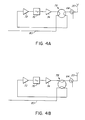
- FIGS. 4a and 4b show in greater detail the band limited time division duplex amplifier 62.
- the band limited time division duplex amplifier 62 which comprises a pair of amplifiers 72 and 74 connected in series, with a band limiting filter 76 connected between the amplifiers 72 and 74.
- the output of the amplifier 76 and the input of the amplifier 72 are connected to respective terminals of a transfer switch indicated generally by reference numeral 78.
- the antenna 20 and a conductor 80, extending from the variable attenuator 60. are connected to two other terminals of the transfer switch 78.
- the transfer switch 78 has two switch states. As shown in Figure 4A, in a first switch state, which is a "receive" state in which the receive signal from the handset 22 is being received by the antenna 20, the transfer switch 78 connects the antenna 20 to the input of the amplifier 72 and also connects the output of the amplifier 78 to the variable attenuator 60, so that the receive signal is amplified by the amplifiers 72 and 74 and the gain is controlled by the variable attenuator 60 so as to counteract attenuation between the antenna 20 and the base station 10.
- a second switch state of the transfer switch 78 as illustrated in Figure 4B, the conductor 80 from the variable attenuator 60 is connected to the input of the amplifier 72, while the output of the amplifier 74 is connected to the antenna 20.
- the transmit signal after attenuation by the variable attenuator 60, is amplified by the amplifiers 72 and 74 to counteract signal loss between the base station and the antenna 20, as described above.
- the changes in the state of the transfer switch 78 are controlled by control outputs from the microprocessor controller 72 in accordance with the timing derived from the transmit and receive signals.
- the amplifiers 72 and 74 are used to amplify both the transmit signals and also the receive signals. and the transmit and receive signal gains are equal.
- the amplifier and switch arrangement shown in Figures 4A and 4B therefore enables the microcell extender 18 to automatically compensate for both the transmit signal loss from the base station 10 to the antenna 20 and, also, the receive signal loss from the antenna 20 to the base station 10.
- Figure 5 shows a modification of the telephone system illustrated in Figure 1. More particularly, in the modification illustrated in Figure 5. an in-line amplifier unit 90, which is similar to the microcell extenders 18 and 19, is connected between the base station extender 12 and the microcell extender 19 for amplifying the transmit and receive signals passing through the co-axial cable 16, and to relay the boosted signals to the microcell extender 19 or the base station extender 12, as the case may be.
- an in-line amplifier unit 90 which is similar to the microcell extenders 18 and 19, is connected between the base station extender 12 and the microcell extender 19 for amplifying the transmit and receive signals passing through the co-axial cable 16, and to relay the boosted signals to the microcell extender 19 or the base station extender 12, as the case may be.
- the in-line amplifier unit 90 is similar to the microcell extender 18 shown in Figure 3, except that the antenna 20 is omitted and is replaced by a co-axial connector 91 ( Figure 3) for connection to a co-axial cable 16A ( Figure 5) extending to the microcell extender 19.
- This arrangement allows microcell extender 10 to be connected to the base station by a physically longer, and hence more lossy, length of co-axial cable.
- a bypass conductor 92 interconnects the co-axial connectors 52 and 91, i.e. the input and output of the in-line amplifier unit 90 and is provided with a switch 94. Closure of the switch 94 connects the 10.7 MHz subcarrier and the power from the connector 52 to the connector 91 and, thus, to the microcell 19.
- the output level of the in-amplifier unit 90 When employing this in-line configuration, it is generally preferable to set the output level of the in-amplifier unit 90 lower than the usual transmit level. This allows the cascaded intermodulation budget for the in-line amplifier unit 90 and the end-of-line microcell extender 19 to be dominated solely by the end-of-line performance. Therefore, in operation, the closure of the switch 94 is detected by the microprocessor controller 72 and the variable attenuator 60 is adjusted by the microprocessor controller 72 in order to ensure that the detected signal level at connector 91 is, typically, one tenth of the signal output level at the base station 10. The in-line transmit gain will equal the in-line receive gain.
- the transmit and receive signals are in the form of time division duplex signals.
- the above-described apparatus of Figures 1. 2 and 3 can be readily adapted for frequency division duplex operation.
- band limited TDD amplifier 62 of Figure 3 is replaced by a band limited FDD amplifier 100, as shown in Figure 6.
- the remaining components of the microcell extender shown in Figure 6 are similar to those of Figure 3 and, therefore, have been referenced by the same reference numerals and will not again be described herein.
- the band limited FDD amplifier 100 of Figure 6 is illustrated in greater detail in Figure 7.
- a conductor 102 from the variable attenuator 60, is connected to a duplexer 104, which supplies the transmit signal through a band limiting filter 106 to a transmit amplifier 108, and which receives. from a band limiting filter 110 and a receive signal amplifier 112, the receive signal, which is then supplied through the conductor 102 to the variable attenuator 60.
- the output of the transmit signal amplifier 108, and the filter 110 are connected to a further duplexer 114, which is connected through the directional coupler 68 to the antenna 20.
- duplexers 104 and 114 may, if required, be replaced by RF splitters/combiners.
- the transmit amplifier 108 and filter 106 are physically distinct from the receive amplifier 112 and filter 110. Since the transmit signal levels are typically many orders of magnitude larger then the receive signal levels, the power detectors 42 ( Figure 2) and 70 ( Figure 3) can easily be used by the microprocessor 72 to distinguish the transmit power levels from the receive signal power levels.
- the receive amplifier 112 of Figure 7 has a known gain relative to the transmit amplifier 108, the receive path gain between the antenna 20 and the base station 10 is again well controlled and determined by the signal level adjustment employed for the transmit signal gain.
- microprocessor 72 of Figure 3 will typically operate as follows, for the concrete example of CT-2 Plus, which has 1 ms transmit and 1 ms receive epochs.
- microprocessors 72 and 44 have so far been described for TDD operation.
- similar software can be employed for FDD operation vis-a-vis level control, but the timing control software may be limited to assisting in FDD-TDMA systems to selecting certain time slots for broadcast/reception by certain array members.
Landscapes
- Engineering & Computer Science (AREA)
- Computer Networks & Wireless Communication (AREA)
- Signal Processing (AREA)
- Radio Relay Systems (AREA)
- Mobile Radio Communication Systems (AREA)
- Transceivers (AREA)
- Input Circuits Of Receivers And Coupling Of Receivers And Audio Equipment (AREA)
Claims (18)
- Dispositif répéteur RF d'un dispositif de téléphonie sans fil, pour diffuser un signal d'émission provenant d'un poste de base (10) à destination d'un appareil mobile (22), et pour fournir au poste de base (10) un signal de réception émis par l'appareil mobile (22), ce dispositif comportant un premier élément répéteur RF (12) qui fonctionne en interface avec le poste de base (10), et au moins un deuxième élément répéteur RF (18,19,90) séparé du premier élément répéteur RF (12), et pourvu d'une antenne pour échanger avec l'appareil mobile (22) des signaux d'émission et de réception sous forme de signaux radio, une ligne de transmission de signaux (14,16,16A) étant prévue pour relier le premier élément répéteur RF (12) au deuxième élément répéteur RF (18,19,90), caractérisé en ce que le premier élément répéteur RF (12) comporte un premier détecteur de niveau (42), pour détecter le niveau du signal d'émission qui parvient au premier élément répéteur RF (12), et un modulateur (46), pour traduire le niveau du signal ainsi détecté en modulant une onde porteuse qui passe sur la ligne de signaux (14,16,16A) vers le deuxième élément répéteur RF (18,19,90), et en ce que le deuxième élément répéteur RF (18,19,90) comporte un régulateur de niveau des signaux (62) pour amplifier le signal d'émission, un deuxième détecteur de niveau (70), pour détecter le niveau du signal d'émission amplifié par le régulateur de niveau (62), un démodulateur (68) pour démoduler le signal de niveau provenant du premier élément répéteur RF (12), et un organe de contrôle (72) pour comparer le niveau du signal démodulé et le niveau du signal détecté par le deuxième détecteur de niveau (70), afin de commander le régulateur de niveau des signaux (62), ce régulateur de niveau (62) ayant un gain variable suivant les ordres de l'organe de contrôle (72), pour augmenter le niveau du signal détecté par le deuxième détecteur de niveau (70), de manière à obtenir un rapport prédéterminé avec le niveau détecté par le premier détecteur de niveau (42).
- Dispositif répéteur RF selon la revendication 1, caractérisé en ce que le régulateur de niveau des signaux (62) comporte un commutateur de transfert (78), pour appliquer altemativement le signal d'émission et le signal de réception au régulateur de niveau des signaux (62), pour que le signal d'émission et le signal de réception soient amplifiés l'un et l'autre avec des gains égaux.
- Dispositif répéteur RF selon la revendication 1, caractérisé en ce que le premier élément répéteur RF (12) comporte un processeur (44), pour quantifier et coder l'émission du premier détecteur de niveau (42), et des moyens pour fixer en conséquence les instants du signal d'émission et du signal de réception émis par le premier détecteur de niveau (42), le modulateur (46) étant sous le contrôle du processeur (44).
- Disposltif répéteur RF selon l'une des revendications 1, 2 ou 3, caractérisé en ce que le premier élément répéteur (12) comporte un organe de jonction (40), pour appliquer le signal d'émission et le signal de réception au premier détecteur de niveau (42), cet organe de jonction (40) étant pourvu d'un sélecteur directionnel pour appliquer le signal d'émission de préférence au premier détecteur de niveau (42), afin de permettre au processeur de distinguer le signal d'émission par rapport au signal de réception.
- Disposltif répéteur RF selon l'une des revendications 1, 2 ou 3, caractérisé en ce que l'organe de contrôle (72) comporte des moyens pour régler les instants des opérations, d'après un signal d'ordre ou signal de balisage émis par le poste de base (10), en l'absence d'une liaison entre ce poste de base et l'appareil mobile.
- Dispositif répéteur RF selon l'une des revendications 1, 2 ou 3, caractérisé en ce que le régulateur de niveau des signaux (62) comporte un commutateur de transfert (78), pour appliquer alternativement le signal d'émission et le signal de réception au régulateur de niveau des signaux (62), le commutateur se trouvant alors tantôt en régime d'émission et tantôt en régime de réception, pour assurer l'amplification du signal d'émission et du signal de réception avec des gains égaux dans les deux cas, l'organe de contrôle (72) comportant des moyens pour changer le régime de fonctionnement du commutateur de transfert (78), suivant les instants fixés par l'organe de contrôle (72) pour le signal d'émission et le signal de réception.
- Dispositif répéteur RF selon la revendication 1, caractérisé en ce qu'il comporte en outre un bloc amplificateur (90) monté en série, relié par la ligne de signaux (16,16A) au poste de base (10) et au deuxième élément répéteur RF (19), ce bloc amplificateur (90) étant pourvu d'un autre régulateur de niveau des signaux (62) pour amplifier le signal d'émission, d'un autre détecteur de niveau (70) pour détecter le niveau du signai d'émission amplifié par le deuxième régulateur de niveau (62), d'un démodulateur (68) pour démoduler les indications de niveau des signaux provenant du premier élément répéteur RF (12), d'un autre organe de contrôle (72), pour comparer les indications démodulées de niveau des signaux et le niveau des signaux détecté par l'autre détecteur de niveau des signaux (70), afin de produire un autre signal de commande destiné à l'autre régulateur de niveau des signaux (62), ce dernier régulateur (62) ayant un gain variable en fonction de l'autre signal de commande, afin d'augmenter le niveau du signal détecté par l'autre détecteur de niveau (70), de manière à obtenir un rapport prédéterminé vis-à-vis du niveau détecté par le premier détecteur de niveau (42).
- Dispositif répéteur RF selon la revendication 7, caractérisé en ce que l'autre régulateur de niveau des signaux (62) comporte un commutateur de transfert (78), pour appliquer alternativement le signal d'émission et le signal de réception à l'autre régulateur de niveau des signaux (62), afin d'assurer l'amplification du signal d'émission et du signal de réception avec des gains égaux dans les deux cas.
- Dispositif répéteur RF selon la revendication 7 ou 8, caractérisé en ce que l'amplificateur (90) monté en série comporte une borne d'entrée (52), une borne de sortie (91), un conducteur de dérivation (92) entre les bornes d'entrée et de sortie, et un commutateur (94) disposé sur le conducteur de dérivation (92) pour relier celui-ci à une source d'alimentation et mettre en communication les bornes d'entrée et de sortie.
- Dispositif répéteur RF selon la revendication 1, caractérisé en ce que le régulateur des signaux est pourvu d'un amplificateur (62,100), pour amplifier les signaux d'émission et de réception, le deuxième détecteur de niveau des signaux (70) détectant le niveau du signal d'émission amplifié par l'amplificateur (62,100) et le niveau du signal de réception intercepté par l'antenne (20), et d'un atténuateur à effet variable (60) monté entre la ligne des signaux (14,16) et l'amplificateur (62,100), en ce que l'organe de contrôle comporte un microprocesseur de commande (72), pour comparer les indications de niveau des signaux démodulés et le niveau du signal d'émission détecté par le deuxième détecteur de niveau des signaux (70), afin de régler en conséquence l'effet de l'atténuateur (60), pour compenser l'atténuation des signaux d'émission et de réception sur la ligne des signaux (14,16), et en ce que le microprocesseur de commande (72) est relié à l'amplificateur (62,100), pour régler celui-ci en fonction des signaux d'émission et de réception.
- Dispositif répéteur RF selon la revendication 10, caractérisé en ce que l'amplificateur (62,100) est pourvu d'une borne d'entrée, d'une borne de sortie, et d'un commutateur de transfert (78) commandé par la cadence alternative fixée par le deuxième microprocesseur (72), tantôt pour relier la borne de sortie à l'antenne (20) afin de diffuser le signal d'émission amplifié, et tantôt pour relier l'antenne à la borne d'entrée afin d'amplifier le signal de réception, de manière à assurer la même amplification pour le signal d'émission et le signal de réception.
- Dispositif répéteur RF selon la revendication 10 ou 11, caractérisé en ce qu'il comporte des commutateurs directionnels (40,64), pour appliquer sélectivement les signaux d'émission et de réception à l'un ou à l'autre des deux détecteurs de niveau (42,70), ces commutateurs directionnels (40,64) étant adaptés à appliquer de préférence le signal d'émission au premier élément répéteur RF (12), et dépendant à cet effet d'un microprocesseur de commande (44) relié au détecteur de niveau des signaux (42) pour quantifier le signal d'émission, et relié également aux deux détecteurs de niveau (42,70) pour permettre aux microprocesseurs (44,72) de distinguer le signal d'émission par rapport au signal de réception.
- Procédé pour diffuser un signal d'émission provenant d'un poste de base (10) à destination d'un appareil mobile (22), et pour fournir au poste de base (10) un signal de réception provenant de l'appareil mobile (22), dans un système de téléphonie sans fil utilisant un dispositif répéteur RF pourvu d'un premier élément répéteur RF (12) qui fonctionne en interface avec le poste de base (10), d'au moins un deuxième élément répéteur RF (18,19) séparé du premier élément répéteur RF (12) et d'une antenne (20) pour échanger des signaux d'émission et de réception avec le poste mobile (22) sous forme de signaux radio, une ligne de transmission des signaux (14,16) étant prévue entre le premier élément répéteur RF (12) et le deuxième élément répéteur RF (18,19), caractérisé en ce qu'il comporte les phases opératoires suivantes: on détecte le niveau du signal de transmission, au moyen du premier élément répéteur RF (12); en fonction du niveau ainsi détecté, on module une onde porteuse envoyée au deuxième élément répéteur RF (18,19) par la ligne de transmission (14,16); on amplifie, à l'endroit du deuxième élément répéteur RF (18,19), le signal ainsi transmis à cet élément; on démodule ensuite ce signal de niveau provenant du premier élément répéteur RF (12); on compare le niveau de ce signal démodulé et le niveau du signal détecté par le deuxième élément répéteur RF (18,19), pour produire un ordre de réglage de l'amplification du signal d'émission, à l'endroit du deuxième élément répéteur RF (18,19); et on diffuse alors vers le poste mobile (22) le signal d'émission ainsi amplifié.
- Procédé selon la revendication 13, caractérisé en ce qu'on applique alternativement à un amplificateur (62,100) le signal d'émission et le signal de réception, pour amplifier le signal d'émission et le signal de réception avec des gains égaux dans les deux cas.
- Procédé selon la revendication 13, caractérisé en ce qu'on règle l'instant du signal d'émission et celui du signal de réception à l'endroit du premier élément répéteur RF (12), pour synchroniser le fonctionnement des deux éléments répéteur RF (12,18,19).
- Procédé selon la revendication 15, caractérisé en ce qu'on utilise un commutateur directionnel (40) associé au premier élément répéteur RF (12), pour appliquer le signal d'émission de préférence à ce premier élément, afin de distinguer le signal d'émission par rapport au signal de réception.
- Procédé selon la revendication 13, caractérisé en ce qu'on fixe les instants de chaque régime de fonctionnement d'après un signal d'ordre ou signal de balisage émis par le poste de base (10), en l'absence d'une liaison entre ce poste et l'appareil mobile.
- Procédé selon la revendication 13, caractérisé en ce qu'on amplifie le signal d'émission et le signal de réception, en les traitant dans un amplificateur (90) disposé entre les deux éléments répéteurs RF (12,18,19), en fonction du niveau du signal détecté par le premier élément répéteur RF (12).
Applications Claiming Priority (3)
| Application Number | Priority Date | Filing Date | Title |
|---|---|---|---|
| US327746 | 1994-10-24 | ||
| US08/327,746 US5634191A (en) | 1994-10-24 | 1994-10-24 | Self-adjusting RF repeater arrangements for wireless telephone systems |
| PCT/CA1995/000591 WO1996013103A1 (fr) | 1994-10-24 | 1995-10-20 | Agencements de repeteurs rf auto-reglables pour systemes de telephonie sans fil |
Publications (2)
| Publication Number | Publication Date |
|---|---|
| EP0788686A1 EP0788686A1 (fr) | 1997-08-13 |
| EP0788686B1 true EP0788686B1 (fr) | 1998-12-09 |
Family
ID=23277870
Family Applications (1)
| Application Number | Title | Priority Date | Filing Date |
|---|---|---|---|
| EP95934025A Expired - Lifetime EP0788686B1 (fr) | 1994-10-24 | 1995-10-20 | Agencements de repeteurs rf auto-reglables pour systemes de telephonie sans fil |
Country Status (7)
| Country | Link |
|---|---|
| US (1) | US5634191A (fr) |
| EP (1) | EP0788686B1 (fr) |
| KR (1) | KR970707655A (fr) |
| AT (1) | ATE174460T1 (fr) |
| AU (1) | AU3648495A (fr) |
| DE (1) | DE69506579D1 (fr) |
| WO (1) | WO1996013103A1 (fr) |
Families Citing this family (71)
| Publication number | Priority date | Publication date | Assignee | Title |
|---|---|---|---|---|
| US5590173A (en) * | 1992-08-05 | 1996-12-31 | Beasley; Andrew S. | Delay insensitive base station-to-handset interface for radio telephone systems |
| US5832364A (en) * | 1995-10-06 | 1998-11-03 | Airnet Communications Corp. | Distributing wireless system carrier signals within a building using existing power line wiring |
| US6128470A (en) * | 1996-07-18 | 2000-10-03 | Ericsson Inc. | System and method for reducing cumulative noise in a distributed antenna network |
| FR2760925B1 (fr) * | 1997-03-11 | 1999-05-14 | France Telecom | Dispositif d'amplification bidirectionnelle dans une borne radio deportee |
| FI973850L (fi) * | 1997-09-30 | 1999-03-31 | Nokia Telecommunications Oy | Menetelmä solukkoradioverkon radiotoistimen radiotaajuuden säätämiseksi |
| US6246868B1 (en) * | 1998-08-14 | 2001-06-12 | Phonex Corporation | Conversion and distribution of incoming wireless telephone signals using the power line |
| EP1383258A3 (fr) | 1999-02-05 | 2004-11-24 | Interdigital Technology Corporation | Station de base avec compensation automatique de l'affaiblissement du cable |
| JP2002536908A (ja) * | 1999-02-05 | 2002-10-29 | インターデイジタル テクノロジー コーポレーション | ケーブル損失自動補償手段を備える送受信局 |
| US7123939B1 (en) | 1999-02-05 | 2006-10-17 | Interdigital Technology Corporation | Communication station with automatic cable loss compensation |
| US6374083B1 (en) * | 1999-03-01 | 2002-04-16 | Nokia Corporation | Apparatus, and associated method, for selectively modifying characteristics of the receive signal received at a receiving station |
| JP3782616B2 (ja) * | 1999-08-31 | 2006-06-07 | 株式会社エヌ・ティ・ティ・ドコモ | ブースター、監視装置、ブースター・システム、制御方法および監視方法 |
| US6268827B1 (en) * | 1999-10-29 | 2001-07-31 | Ball Aerospace & Technologies Corp. | Method and apparatus for carrying signals having different frequencies in a space-deployed antenna system |
| US6842459B1 (en) | 2000-04-19 | 2005-01-11 | Serconet Ltd. | Network combining wired and non-wired segments |
| CA2323881A1 (fr) * | 2000-10-18 | 2002-04-18 | Dps Wireless Inc. | Repeteur personnel adaptatif |
| US6748194B2 (en) * | 2001-02-28 | 2004-06-08 | Korea Telecom M.Com Co., Ltd. | Repeater system having oscillation preventing function and automatic reverse output disabling function for non-subscriber and control method thereof |
| NZ511155A (en) * | 2001-04-18 | 2002-12-20 | Tait Electronics Ltd | A system for allocation of a control channel at a base station in a trunked network using a plurality of repeaters which provide respective radio channels |
| US7565106B1 (en) | 2001-04-26 | 2009-07-21 | Sprint Spectrum L.P. | Wireless signal repeater with temperature and time display |
| IL161190A0 (en) | 2001-10-11 | 2004-08-31 | Serconet Ltd | Outlet with analog signal adapter, method for use thereof and a network using said outlet |
| DE60219213T2 (de) * | 2001-11-20 | 2008-01-24 | Qualcomm, Inc., San Diego | Rückstreckenleistungsgeregelter zwischenverstärker |
| KR100412014B1 (ko) * | 2001-12-13 | 2003-12-24 | 주식회사 에이스테크놀로지 | 전력제어 기능을 갖는 중간 주파수 방식의 중계기와전력제어 방법 |
| US6904266B1 (en) * | 2002-02-19 | 2005-06-07 | Navini Networks, Inc. | Wireless enhancer using a switch matrix |
| US7050758B2 (en) * | 2002-02-28 | 2006-05-23 | Nortel Networks Limited | Self-configuring repeater system and method |
| US6990313B1 (en) | 2002-03-14 | 2006-01-24 | Sprint Communications Company L.P. | Wireless repeater with intelligent signal display |
| KR100487234B1 (ko) * | 2002-07-02 | 2005-05-03 | 삼성전자주식회사 | 이동통신 기지국 시스템 |
| US7831263B2 (en) | 2002-11-08 | 2010-11-09 | Qualcomm Incorporated | Apparatus and method for determining the location of a repeater |
| IL152824A (en) * | 2002-11-13 | 2012-05-31 | Mosaid Technologies Inc | A socket that can be connected to and the network that uses it |
| US20040166802A1 (en) * | 2003-02-26 | 2004-08-26 | Ems Technologies, Inc. | Cellular signal enhancer |
| IL157787A (en) * | 2003-09-07 | 2010-12-30 | Mosaid Technologies Inc | Modular outlet for data communications network |
| IL159838A0 (en) | 2004-01-13 | 2004-06-20 | Yehuda Binder | Information device |
| IL160417A (en) * | 2004-02-16 | 2011-04-28 | Mosaid Technologies Inc | Unit added to the outlet |
| CA2562045A1 (fr) | 2004-04-05 | 2005-11-03 | Qualcomm Incorporated | Repeteur concu pour indiquer les noeuds voisins detectes |
| WO2005103753A1 (fr) | 2004-04-05 | 2005-11-03 | Qualcomm Incorporated | Repeteur telephonique dote de capacites de localisation |
| IL161869A (en) | 2004-05-06 | 2014-05-28 | Serconet Ltd | A system and method for carrying a signal originating is wired using wires |
| US7778596B2 (en) | 2004-07-29 | 2010-08-17 | Qualcomm Incorporated | Airlink sensing watermarking repeater |
| US20060189276A1 (en) * | 2004-12-08 | 2006-08-24 | Michael Halinski | Methods and systems for intelligent adaptive gain control |
| US20070008939A1 (en) * | 2005-06-10 | 2007-01-11 | Adc Telecommunications, Inc. | Providing wireless coverage into substantially closed environments |
| US7656957B2 (en) * | 2005-06-24 | 2010-02-02 | Cisco Technology, Inc. | Multiplexing system for time division duplex communication systems |
| US7813451B2 (en) | 2006-01-11 | 2010-10-12 | Mobileaccess Networks Ltd. | Apparatus and method for frequency shifting of a wireless signal and systems using frequency shifting |
| US20070232228A1 (en) * | 2006-04-04 | 2007-10-04 | Mckay David L Sr | Wireless repeater with universal server base unit and modular donor antenna options |
| US7783318B2 (en) * | 2006-09-26 | 2010-08-24 | Wilson Electronics | Cellular network amplifier with automated output power control |
| US20080125187A1 (en) * | 2006-11-03 | 2008-05-29 | Yu-Chuan Chang | Wireless transmission system suitable for large space and method thereof |
| KR100870694B1 (ko) * | 2006-12-11 | 2008-11-26 | (주)씨앤드에스 마이크로 웨이브 | 알에프 케이블 손실을 보상하는 보상기를 구비한 아이에프분산중계기 |
| US8023999B2 (en) * | 2006-12-28 | 2011-09-20 | Alcatel Lucent | Base station architecture using decentralized duplexers |
| US7903599B1 (en) | 2007-09-12 | 2011-03-08 | Sprint Spectrum L.P. | Call-detection algorithm for mitigating interference by low-cost internet-base-station (LCIB) pilot beacons with macro-network communications |
| US7974230B1 (en) | 2007-09-12 | 2011-07-05 | Sprint Spectrum L.P. | Mitigating interference by low-cost internet-base-station (LCIB) pilot beacons with macro-network communications |
| WO2009053910A2 (fr) | 2007-10-22 | 2009-04-30 | Mobileaccess Networks Ltd. | Système de communication utilisant des fils à faible bande passante |
| US8559339B1 (en) | 2007-11-14 | 2013-10-15 | Sprint Spectrum L.P. | Low-cost-internet-base-station-(LCIB) user-adaptation algorithm |
| US8175649B2 (en) | 2008-06-20 | 2012-05-08 | Corning Mobileaccess Ltd | Method and system for real time control of an active antenna over a distributed antenna system |
| US8184598B1 (en) | 2008-05-29 | 2012-05-22 | Sprint Spectrum L.P. | Low-cost internet-base-station (LCIB) radio-frequency (RF) adaptation using stationary transceivers |
| US8310963B2 (en) * | 2008-06-24 | 2012-11-13 | Adc Telecommunications, Inc. | System and method for synchronized time-division duplex signal switching |
| US7974653B1 (en) | 2008-08-12 | 2011-07-05 | Sprint Spectrum L.P. | Manually configuring low-cost Internet-base-station (LCIB) coverage using an associated mobile station |
| CN102232191B (zh) | 2009-02-08 | 2015-07-08 | 康宁移动接入有限公司 | 采用携带以太网信号的电缆的通信系统 |
| US20100302999A1 (en) * | 2009-05-29 | 2010-12-02 | Yan Hui | Method and apparatus for relaying in wireless networks |
| US8472579B2 (en) | 2010-07-28 | 2013-06-25 | Adc Telecommunications, Inc. | Distributed digital reference clock |
| US8532242B2 (en) | 2010-10-27 | 2013-09-10 | Adc Telecommunications, Inc. | Distributed antenna system with combination of both all digital transport and hybrid digital/analog transport |
| US8462683B2 (en) | 2011-01-12 | 2013-06-11 | Adc Telecommunications, Inc. | Distinct transport path for MIMO transmissions in distributed antenna systems |
| US8804670B1 (en) | 2011-02-17 | 2014-08-12 | Sprint Spectrum L.P. | Method and system for management of inter-frequency handoff |
| US8693342B2 (en) | 2011-10-28 | 2014-04-08 | Adc Telecommunications, Inc. | Distributed antenna system using time division duplexing scheme |
| EP2829152A2 (fr) | 2012-03-23 | 2015-01-28 | Corning Optical Communications Wireless Ltd. | Puce(s) de circuit intégré à radiofréquence (rfic) servant à fournir des fonctionnalités de système d'antenne à répartition, et composants, systèmes, et procédés connexes |
| WO2014130797A1 (fr) | 2013-02-22 | 2014-08-28 | Adc Telecommunications, Inc. | Tête radio distante universelle |
| CA2914104C (fr) | 2013-02-22 | 2022-12-13 | Adc Telecommunications, Inc. | Reference principale pour interface reseau de stations de base emanant d'un systeme d'antennes distribuees |
| CA2814303A1 (fr) | 2013-04-26 | 2014-10-26 | Cellphone-Mate, Inc. | Appareil et procedes pour amplificateurs de signaux de frequence radio |
| DE102013207898A1 (de) | 2013-04-30 | 2014-10-30 | Novero Dabendorf Gmbh | Kompensation einer Signal-Dämpfung bei der Übertragung von Sendesignalen eines Mobilfunkgeräts |
| US9420557B2 (en) | 2013-08-27 | 2016-08-16 | At&T Mobility Ii Llc | Radio repeater system for avoiding mobile device location interference |
| US9787457B2 (en) | 2013-10-07 | 2017-10-10 | Commscope Technologies Llc | Systems and methods for integrating asynchronous signals in distributed antenna system with direct digital interface to base station |
| AU2015274511B2 (en) | 2014-06-11 | 2019-08-15 | Outdoor Wireless Networks LLC | Bitrate efficient transport through distributed antenna systems |
| US9184960B1 (en) | 2014-09-25 | 2015-11-10 | Corning Optical Communications Wireless Ltd | Frequency shifting a communications signal(s) in a multi-frequency distributed antenna system (DAS) to avoid or reduce frequency interference |
| US10499269B2 (en) | 2015-11-12 | 2019-12-03 | Commscope Technologies Llc | Systems and methods for assigning controlled nodes to channel interfaces of a controller |
| EP3610584A4 (fr) * | 2017-04-11 | 2020-12-16 | Wilson Electronics, LLC | Amplificateur de signal à connexions de câbles coaxiaux |
| DE102018207430B4 (de) | 2018-05-14 | 2020-02-06 | Laird Dabendorf Gmbh | Antenneneinheit, Sendesystem und Verfahren zum Betreiben einer Antenneneinheit |
| EP3863191B1 (fr) | 2020-02-04 | 2025-11-05 | Nokia Solutions and Networks Oy | Système de communication |
Family Cites Families (10)
| Publication number | Priority date | Publication date | Assignee | Title |
|---|---|---|---|---|
| US3146397A (en) * | 1960-05-23 | 1964-08-25 | Collins Radio Co | Multiple-pole two-position dual-wafer ultra-high-frequency transmit-receive switch control |
| DE3126195C2 (de) * | 1981-07-03 | 1986-04-17 | Licentia Patent-Verwaltungs-Gmbh, 6000 Frankfurt | Gleichwellenfunknetz |
| JPS6041821A (ja) * | 1983-08-18 | 1985-03-05 | Nec Corp | 送信出力電力制御装置 |
| US5095528A (en) * | 1988-10-28 | 1992-03-10 | Orion Industries, Inc. | Repeater with feedback oscillation control |
| US5187803A (en) * | 1990-01-18 | 1993-02-16 | Andrew Corporation | Regenerative rf bi-directional amplifier system |
| JP2778794B2 (ja) * | 1990-03-30 | 1998-07-23 | 日本電信電話株式会社 | 移動伝搬遅延軽減方法 |
| US5321849A (en) * | 1991-05-22 | 1994-06-14 | Southwestern Bell Technology Resources, Inc. | System for controlling signal level at both ends of a transmission link based on a detected valve |
| CA2058736C (fr) * | 1992-01-03 | 1995-02-14 | Andrew S. Beasley | Systeme de repeteurs rf repartis pour telephones sans fil |
| AU667140B2 (en) * | 1992-11-26 | 1996-03-07 | Nec Corporation | Booster for use in combination with radio apparatus |
| AU672054B2 (en) * | 1992-12-30 | 1996-09-19 | Radio Communication Systems Ltd. | Bothway RF repeater for personal communications systems |
-
1994
- 1994-10-24 US US08/327,746 patent/US5634191A/en not_active Expired - Lifetime
-
1995
- 1995-10-20 KR KR1019970702602A patent/KR970707655A/ko not_active Withdrawn
- 1995-10-20 AU AU36484/95A patent/AU3648495A/en not_active Abandoned
- 1995-10-20 AT AT95934025T patent/ATE174460T1/de not_active IP Right Cessation
- 1995-10-20 EP EP95934025A patent/EP0788686B1/fr not_active Expired - Lifetime
- 1995-10-20 DE DE69506579T patent/DE69506579D1/de not_active Expired - Lifetime
- 1995-10-20 WO PCT/CA1995/000591 patent/WO1996013103A1/fr not_active Ceased
Also Published As
| Publication number | Publication date |
|---|---|
| EP0788686A1 (fr) | 1997-08-13 |
| DE69506579D1 (de) | 1999-01-21 |
| US5634191A (en) | 1997-05-27 |
| AU3648495A (en) | 1996-05-15 |
| KR970707655A (ko) | 1997-12-01 |
| WO1996013103A1 (fr) | 1996-05-02 |
| ATE174460T1 (de) | 1998-12-15 |
Similar Documents
| Publication | Publication Date | Title |
|---|---|---|
| EP0788686B1 (fr) | Agencements de repeteurs rf auto-reglables pour systemes de telephonie sans fil | |
| AU695358B2 (en) | Cellular radio system, repeater and base station | |
| EP2136491B1 (fr) | Système et procedé d'amplification et de surveillance d'amplificateurs | |
| EP2018714B1 (fr) | Répéteur sans fil avec configuration maître/esclave | |
| US6480702B1 (en) | Apparatus and method for distributing wireless communications signals to remote cellular antennas | |
| CA2087285C (fr) | Repeteurs rf pour systemes telephoniques duplex sans fil a multiplexage temporel | |
| EP1091508B1 (fr) | Installation de repetition utilisant des lignes telephoniques et dediées | |
| US6201795B1 (en) | Method and apparatus for mitigating interference in a communication system | |
| UA44762C2 (uk) | Приймально-передавальна система радіотелефонного зв'язку і спосіб приймання рч-сигналу | |
| EP0468688B1 (fr) | Méthode et appareil pour établir des communications sans fil entre des endroits éloignés | |
| US6513163B1 (en) | Embedded forward reference and control | |
| CA2134365C (fr) | Repeteur rf a deux etages a reglage automatique pour systemes de telephonie sans fil | |
| EP2044704B1 (fr) | Distribution de signaux de fréquences radio utilisant un système de câble de données | |
| CA2232615A1 (fr) | Systeme a deux emetteurs avec commutation de secours | |
| JP3300552B2 (ja) | 光ケーブルを利用した中継装置 | |
| CN1169802A (zh) | 用于无线电话系统的自调整射频转发器 | |
| US5867792A (en) | Radio communication system | |
| KR100377935B1 (ko) | 무선 기지국의 인접채널파워 모니터링 시스템 | |
| KR100668106B1 (ko) | 기지국 시스템의 시간지연 보정장치 | |
| KR20030084078A (ko) | 이동통신망을 이용한 무선랜 서비스 시스템 | |
| HK1004971A (en) | Self-adjusting rf repeater arrangements for wireless telephone systems | |
| KR101029979B1 (ko) | 무선통신 중계장치 및 방법 |
Legal Events
| Date | Code | Title | Description |
|---|---|---|---|
| PUAI | Public reference made under article 153(3) epc to a published international application that has entered the european phase |
Free format text: ORIGINAL CODE: 0009012 |
|
| 17P | Request for examination filed |
Effective date: 19970512 |
|
| AK | Designated contracting states |
Kind code of ref document: A1 Designated state(s): AT BE CH DE DK ES FR GB GR IE IT LI LU NL PT SE |
|
| GRAG | Despatch of communication of intention to grant |
Free format text: ORIGINAL CODE: EPIDOS AGRA |
|
| RAP1 | Party data changed (applicant data changed or rights of an application transferred) |
Owner name: ALLEN TELECOM, INC |
|
| 17Q | First examination report despatched |
Effective date: 19980223 |
|
| GRAG | Despatch of communication of intention to grant |
Free format text: ORIGINAL CODE: EPIDOS AGRA |
|
| GRAH | Despatch of communication of intention to grant a patent |
Free format text: ORIGINAL CODE: EPIDOS IGRA |
|
| GRAH | Despatch of communication of intention to grant a patent |
Free format text: ORIGINAL CODE: EPIDOS IGRA |
|
| GRAA | (expected) grant |
Free format text: ORIGINAL CODE: 0009210 |
|
| AK | Designated contracting states |
Kind code of ref document: B1 Designated state(s): AT BE CH DE DK ES FR GB GR IE IT LI LU NL PT SE |
|
| PG25 | Lapsed in a contracting state [announced via postgrant information from national office to epo] |
Ref country code: NL Free format text: LAPSE BECAUSE OF FAILURE TO SUBMIT A TRANSLATION OF THE DESCRIPTION OR TO PAY THE FEE WITHIN THE PRESCRIBED TIME-LIMIT Effective date: 19981209 Ref country code: LI Free format text: LAPSE BECAUSE OF FAILURE TO SUBMIT A TRANSLATION OF THE DESCRIPTION OR TO PAY THE FEE WITHIN THE PRESCRIBED TIME-LIMIT Effective date: 19981209 Ref country code: IT Free format text: LAPSE BECAUSE OF FAILURE TO SUBMIT A TRANSLATION OF THE DESCRIPTION OR TO PAY THE FEE WITHIN THE PRE;WARNING: LAPSES OF ITALIAN PATENTS WITH EFFECTIVE DATE BEFORE 2007 MAY HAVE OCCURRED AT ANY TIME BEFORE 2007. THE CORRECT EFFECTIVE DATE MAY BE DIFFERENT FROM THE ONE RECORDED.SCRIBED TIME-LIMIT Effective date: 19981209 Ref country code: GR Free format text: LAPSE BECAUSE OF NON-PAYMENT OF DUE FEES Effective date: 19981209 Ref country code: ES Free format text: THE PATENT HAS BEEN ANNULLED BY A DECISION OF A NATIONAL AUTHORITY Effective date: 19981209 Ref country code: CH Free format text: LAPSE BECAUSE OF FAILURE TO SUBMIT A TRANSLATION OF THE DESCRIPTION OR TO PAY THE FEE WITHIN THE PRESCRIBED TIME-LIMIT Effective date: 19981209 Ref country code: BE Free format text: LAPSE BECAUSE OF FAILURE TO SUBMIT A TRANSLATION OF THE DESCRIPTION OR TO PAY THE FEE WITHIN THE PRESCRIBED TIME-LIMIT Effective date: 19981209 Ref country code: AT Free format text: LAPSE BECAUSE OF FAILURE TO SUBMIT A TRANSLATION OF THE DESCRIPTION OR TO PAY THE FEE WITHIN THE PRESCRIBED TIME-LIMIT Effective date: 19981209 |
|
| REF | Corresponds to: |
Ref document number: 174460 Country of ref document: AT Date of ref document: 19981215 Kind code of ref document: T |
|
| REG | Reference to a national code |
Ref country code: CH Ref legal event code: EP |
|
| REF | Corresponds to: |
Ref document number: 69506579 Country of ref document: DE Date of ref document: 19990121 |
|
| REG | Reference to a national code |
Ref country code: IE Ref legal event code: FG4D |
|
| PG25 | Lapsed in a contracting state [announced via postgrant information from national office to epo] |
Ref country code: SE Free format text: LAPSE BECAUSE OF FAILURE TO SUBMIT A TRANSLATION OF THE DESCRIPTION OR TO PAY THE FEE WITHIN THE PRESCRIBED TIME-LIMIT Effective date: 19990309 Ref country code: PT Free format text: LAPSE BECAUSE OF FAILURE TO SUBMIT A TRANSLATION OF THE DESCRIPTION OR TO PAY THE FEE WITHIN THE PRESCRIBED TIME-LIMIT Effective date: 19990309 Ref country code: DK Free format text: LAPSE BECAUSE OF FAILURE TO SUBMIT A TRANSLATION OF THE DESCRIPTION OR TO PAY THE FEE WITHIN THE PRESCRIBED TIME-LIMIT Effective date: 19990309 |
|
| PG25 | Lapsed in a contracting state [announced via postgrant information from national office to epo] |
Ref country code: DE Free format text: LAPSE BECAUSE OF FAILURE TO SUBMIT A TRANSLATION OF THE DESCRIPTION OR TO PAY THE FEE WITHIN THE PRESCRIBED TIME-LIMIT Effective date: 19990310 |
|
| ET | Fr: translation filed | ||
| NLV1 | Nl: lapsed or annulled due to failure to fulfill the requirements of art. 29p and 29m of the patents act | ||
| REG | Reference to a national code |
Ref country code: CH Ref legal event code: PL |
|
| PLBE | No opposition filed within time limit |
Free format text: ORIGINAL CODE: 0009261 |
|
| STAA | Information on the status of an ep patent application or granted ep patent |
Free format text: STATUS: NO OPPOSITION FILED WITHIN TIME LIMIT |
|
| PG25 | Lapsed in a contracting state [announced via postgrant information from national office to epo] |
Ref country code: LU Free format text: LAPSE BECAUSE OF NON-PAYMENT OF DUE FEES Effective date: 19991020 Ref country code: IE Free format text: LAPSE BECAUSE OF NON-PAYMENT OF DUE FEES Effective date: 19991020 |
|
| 26N | No opposition filed | ||
| REG | Reference to a national code |
Ref country code: IE Ref legal event code: MM4A |
|
| PGFP | Annual fee paid to national office [announced via postgrant information from national office to epo] |
Ref country code: FR Payment date: 20001024 Year of fee payment: 6 |
|
| REG | Reference to a national code |
Ref country code: GB Ref legal event code: IF02 |
|
| PG25 | Lapsed in a contracting state [announced via postgrant information from national office to epo] |
Ref country code: FR Free format text: LAPSE BECAUSE OF NON-PAYMENT OF DUE FEES Effective date: 20020628 |
|
| REG | Reference to a national code |
Ref country code: FR Ref legal event code: ST |
|
| PGFP | Annual fee paid to national office [announced via postgrant information from national office to epo] |
Ref country code: GB Payment date: 20081015 Year of fee payment: 14 |
|
| PG25 | Lapsed in a contracting state [announced via postgrant information from national office to epo] |
Ref country code: GB Free format text: LAPSE BECAUSE OF NON-PAYMENT OF DUE FEES Effective date: 20091020 |