EP0788773A1 - Werkzeug zum Implantieren einer Endoprothese - Google Patents
Werkzeug zum Implantieren einer Endoprothese Download PDFInfo
- Publication number
- EP0788773A1 EP0788773A1 EP97101786A EP97101786A EP0788773A1 EP 0788773 A1 EP0788773 A1 EP 0788773A1 EP 97101786 A EP97101786 A EP 97101786A EP 97101786 A EP97101786 A EP 97101786A EP 0788773 A1 EP0788773 A1 EP 0788773A1
- Authority
- EP
- European Patent Office
- Prior art keywords
- handle
- rasp body
- tool according
- rasp
- corresponds
- Prior art date
- Legal status (The legal status is an assumption and is not a legal conclusion. Google has not performed a legal analysis and makes no representation as to the accuracy of the status listed.)
- Withdrawn
Links
- 210000000988 bone and bone Anatomy 0.000 claims abstract description 16
- 230000008878 coupling Effects 0.000 claims description 18
- 238000010168 coupling process Methods 0.000 claims description 18
- 238000005859 coupling reaction Methods 0.000 claims description 18
- 238000003801 milling Methods 0.000 abstract description 5
- 210000003746 feather Anatomy 0.000 description 2
- 238000000034 method Methods 0.000 description 2
- 238000002271 resection Methods 0.000 description 2
- FGRBYDKOBBBPOI-UHFFFAOYSA-N 10,10-dioxo-2-[4-(N-phenylanilino)phenyl]thioxanthen-9-one Chemical compound O=C1c2ccccc2S(=O)(=O)c2ccc(cc12)-c1ccc(cc1)N(c1ccccc1)c1ccccc1 FGRBYDKOBBBPOI-UHFFFAOYSA-N 0.000 description 1
- 230000006978 adaptation Effects 0.000 description 1
- 239000002639 bone cement Substances 0.000 description 1
- 239000004568 cement Substances 0.000 description 1
- 238000011161 development Methods 0.000 description 1
- 230000018109 developmental process Effects 0.000 description 1
- 239000007943 implant Substances 0.000 description 1
- 238000011065 in-situ storage Methods 0.000 description 1
- 238000003754 machining Methods 0.000 description 1
- 238000003860 storage Methods 0.000 description 1
Images


Classifications
-
- A—HUMAN NECESSITIES
- A61—MEDICAL OR VETERINARY SCIENCE; HYGIENE
- A61F—FILTERS IMPLANTABLE INTO BLOOD VESSELS; PROSTHESES; DEVICES PROVIDING PATENCY TO, OR PREVENTING COLLAPSING OF, TUBULAR STRUCTURES OF THE BODY, e.g. STENTS; ORTHOPAEDIC, NURSING OR CONTRACEPTIVE DEVICES; FOMENTATION; TREATMENT OR PROTECTION OF EYES OR EARS; BANDAGES, DRESSINGS OR ABSORBENT PADS; FIRST-AID KITS
- A61F2/00—Filters implantable into blood vessels; Prostheses, i.e. artificial substitutes or replacements for parts of the body; Appliances for connecting them with the body; Devices providing patency to, or preventing collapsing of, tubular structures of the body, e.g. stents
- A61F2/02—Prostheses implantable into the body
- A61F2/30—Joints
- A61F2/46—Special tools for implanting artificial joints
- A61F2/4684—Trial or dummy prostheses
-
- A—HUMAN NECESSITIES
- A61—MEDICAL OR VETERINARY SCIENCE; HYGIENE
- A61B—DIAGNOSIS; SURGERY; IDENTIFICATION
- A61B17/00—Surgical instruments, devices or methods
- A61B17/16—Instruments for performing osteoclasis; Drills or chisels for bones; Trepans
- A61B17/1659—Surgical rasps, files, planes, or scrapers
-
- A—HUMAN NECESSITIES
- A61—MEDICAL OR VETERINARY SCIENCE; HYGIENE
- A61B—DIAGNOSIS; SURGERY; IDENTIFICATION
- A61B17/00—Surgical instruments, devices or methods
- A61B2017/0046—Surgical instruments, devices or methods with a releasable handle; with handle and operating part separable
-
- A—HUMAN NECESSITIES
- A61—MEDICAL OR VETERINARY SCIENCE; HYGIENE
- A61B—DIAGNOSIS; SURGERY; IDENTIFICATION
- A61B17/00—Surgical instruments, devices or methods
- A61B2017/00477—Coupling
-
- A—HUMAN NECESSITIES
- A61—MEDICAL OR VETERINARY SCIENCE; HYGIENE
- A61F—FILTERS IMPLANTABLE INTO BLOOD VESSELS; PROSTHESES; DEVICES PROVIDING PATENCY TO, OR PREVENTING COLLAPSING OF, TUBULAR STRUCTURES OF THE BODY, e.g. STENTS; ORTHOPAEDIC, NURSING OR CONTRACEPTIVE DEVICES; FOMENTATION; TREATMENT OR PROTECTION OF EYES OR EARS; BANDAGES, DRESSINGS OR ABSORBENT PADS; FIRST-AID KITS
- A61F2/00—Filters implantable into blood vessels; Prostheses, i.e. artificial substitutes or replacements for parts of the body; Appliances for connecting them with the body; Devices providing patency to, or preventing collapsing of, tubular structures of the body, e.g. stents
- A61F2/02—Prostheses implantable into the body
- A61F2/30—Joints
- A61F2/32—Joints for the hip
- A61F2/36—Femoral heads ; Femoral endoprostheses
- A61F2/3662—Femoral shafts
-
- A—HUMAN NECESSITIES
- A61—MEDICAL OR VETERINARY SCIENCE; HYGIENE
- A61F—FILTERS IMPLANTABLE INTO BLOOD VESSELS; PROSTHESES; DEVICES PROVIDING PATENCY TO, OR PREVENTING COLLAPSING OF, TUBULAR STRUCTURES OF THE BODY, e.g. STENTS; ORTHOPAEDIC, NURSING OR CONTRACEPTIVE DEVICES; FOMENTATION; TREATMENT OR PROTECTION OF EYES OR EARS; BANDAGES, DRESSINGS OR ABSORBENT PADS; FIRST-AID KITS
- A61F2/00—Filters implantable into blood vessels; Prostheses, i.e. artificial substitutes or replacements for parts of the body; Appliances for connecting them with the body; Devices providing patency to, or preventing collapsing of, tubular structures of the body, e.g. stents
- A61F2/02—Prostheses implantable into the body
- A61F2/30—Joints
- A61F2/46—Special tools for implanting artificial joints
- A61F2/4603—Special tools for implanting artificial joints for insertion or extraction of endoprosthetic joints or of accessories thereof
-
- A—HUMAN NECESSITIES
- A61—MEDICAL OR VETERINARY SCIENCE; HYGIENE
- A61F—FILTERS IMPLANTABLE INTO BLOOD VESSELS; PROSTHESES; DEVICES PROVIDING PATENCY TO, OR PREVENTING COLLAPSING OF, TUBULAR STRUCTURES OF THE BODY, e.g. STENTS; ORTHOPAEDIC, NURSING OR CONTRACEPTIVE DEVICES; FOMENTATION; TREATMENT OR PROTECTION OF EYES OR EARS; BANDAGES, DRESSINGS OR ABSORBENT PADS; FIRST-AID KITS
- A61F2/00—Filters implantable into blood vessels; Prostheses, i.e. artificial substitutes or replacements for parts of the body; Appliances for connecting them with the body; Devices providing patency to, or preventing collapsing of, tubular structures of the body, e.g. stents
- A61F2/02—Prostheses implantable into the body
- A61F2/30—Joints
- A61F2002/30001—Additional features of subject-matter classified in A61F2/28, A61F2/30 and subgroups thereof
- A61F2002/30316—The prosthesis having different structural features at different locations within the same prosthesis; Connections between prosthetic parts; Special structural features of bone or joint prostheses not otherwise provided for
- A61F2002/30329—Connections or couplings between prosthetic parts, e.g. between modular parts; Connecting elements
- A61F2002/30331—Connections or couplings between prosthetic parts, e.g. between modular parts; Connecting elements made by longitudinally pushing a protrusion into a complementarily-shaped recess, e.g. held by friction fit
- A61F2002/30354—Cylindrically-shaped protrusion and recess, e.g. cylinder of circular basis
-
- A—HUMAN NECESSITIES
- A61—MEDICAL OR VETERINARY SCIENCE; HYGIENE
- A61F—FILTERS IMPLANTABLE INTO BLOOD VESSELS; PROSTHESES; DEVICES PROVIDING PATENCY TO, OR PREVENTING COLLAPSING OF, TUBULAR STRUCTURES OF THE BODY, e.g. STENTS; ORTHOPAEDIC, NURSING OR CONTRACEPTIVE DEVICES; FOMENTATION; TREATMENT OR PROTECTION OF EYES OR EARS; BANDAGES, DRESSINGS OR ABSORBENT PADS; FIRST-AID KITS
- A61F2/00—Filters implantable into blood vessels; Prostheses, i.e. artificial substitutes or replacements for parts of the body; Appliances for connecting them with the body; Devices providing patency to, or preventing collapsing of, tubular structures of the body, e.g. stents
- A61F2/02—Prostheses implantable into the body
- A61F2/30—Joints
- A61F2002/30001—Additional features of subject-matter classified in A61F2/28, A61F2/30 and subgroups thereof
- A61F2002/30316—The prosthesis having different structural features at different locations within the same prosthesis; Connections between prosthetic parts; Special structural features of bone or joint prostheses not otherwise provided for
- A61F2002/30329—Connections or couplings between prosthetic parts, e.g. between modular parts; Connecting elements
- A61F2002/30331—Connections or couplings between prosthetic parts, e.g. between modular parts; Connecting elements made by longitudinally pushing a protrusion into a complementarily-shaped recess, e.g. held by friction fit
- A61F2002/30362—Connections or couplings between prosthetic parts, e.g. between modular parts; Connecting elements made by longitudinally pushing a protrusion into a complementarily-shaped recess, e.g. held by friction fit with possibility of relative movement between the protrusion and the recess
- A61F2002/30364—Rotation about the common longitudinal axis
- A61F2002/30367—Rotation about the common longitudinal axis with additional means for preventing said rotation
-
- A—HUMAN NECESSITIES
- A61—MEDICAL OR VETERINARY SCIENCE; HYGIENE
- A61F—FILTERS IMPLANTABLE INTO BLOOD VESSELS; PROSTHESES; DEVICES PROVIDING PATENCY TO, OR PREVENTING COLLAPSING OF, TUBULAR STRUCTURES OF THE BODY, e.g. STENTS; ORTHOPAEDIC, NURSING OR CONTRACEPTIVE DEVICES; FOMENTATION; TREATMENT OR PROTECTION OF EYES OR EARS; BANDAGES, DRESSINGS OR ABSORBENT PADS; FIRST-AID KITS
- A61F2/00—Filters implantable into blood vessels; Prostheses, i.e. artificial substitutes or replacements for parts of the body; Appliances for connecting them with the body; Devices providing patency to, or preventing collapsing of, tubular structures of the body, e.g. stents
- A61F2/02—Prostheses implantable into the body
- A61F2/30—Joints
- A61F2/32—Joints for the hip
- A61F2/36—Femoral heads ; Femoral endoprostheses
- A61F2/3609—Femoral heads or necks; Connections of endoprosthetic heads or necks to endoprosthetic femoral shafts
- A61F2002/3625—Necks
- A61F2002/3631—Necks with an integral complete or partial peripheral collar or bearing shoulder at its base
-
- A—HUMAN NECESSITIES
- A61—MEDICAL OR VETERINARY SCIENCE; HYGIENE
- A61F—FILTERS IMPLANTABLE INTO BLOOD VESSELS; PROSTHESES; DEVICES PROVIDING PATENCY TO, OR PREVENTING COLLAPSING OF, TUBULAR STRUCTURES OF THE BODY, e.g. STENTS; ORTHOPAEDIC, NURSING OR CONTRACEPTIVE DEVICES; FOMENTATION; TREATMENT OR PROTECTION OF EYES OR EARS; BANDAGES, DRESSINGS OR ABSORBENT PADS; FIRST-AID KITS
- A61F2/00—Filters implantable into blood vessels; Prostheses, i.e. artificial substitutes or replacements for parts of the body; Appliances for connecting them with the body; Devices providing patency to, or preventing collapsing of, tubular structures of the body, e.g. stents
- A61F2/02—Prostheses implantable into the body
- A61F2/30—Joints
- A61F2/32—Joints for the hip
- A61F2/36—Femoral heads ; Femoral endoprostheses
- A61F2/3609—Femoral heads or necks; Connections of endoprosthetic heads or necks to endoprosthetic femoral shafts
- A61F2002/3652—Connections of necks to shafts
-
- A—HUMAN NECESSITIES
- A61—MEDICAL OR VETERINARY SCIENCE; HYGIENE
- A61F—FILTERS IMPLANTABLE INTO BLOOD VESSELS; PROSTHESES; DEVICES PROVIDING PATENCY TO, OR PREVENTING COLLAPSING OF, TUBULAR STRUCTURES OF THE BODY, e.g. STENTS; ORTHOPAEDIC, NURSING OR CONTRACEPTIVE DEVICES; FOMENTATION; TREATMENT OR PROTECTION OF EYES OR EARS; BANDAGES, DRESSINGS OR ABSORBENT PADS; FIRST-AID KITS
- A61F2220/00—Fixations or connections for prostheses classified in groups A61F2/00 - A61F2/26 or A61F2/82 or A61F9/00 or A61F11/00 or subgroups thereof
- A61F2220/0025—Connections or couplings between prosthetic parts, e.g. between modular parts; Connecting elements
- A61F2220/0033—Connections or couplings between prosthetic parts, e.g. between modular parts; Connecting elements made by longitudinally pushing a protrusion into a complementary-shaped recess, e.g. held by friction fit
Definitions
- the invention relates to a tool for implanting an endoprosthesis into the cavity of a human bone, with a rasp body which has a shape which corresponds to the prosthesis shaft to be anchored in the bone cavity.
- Tools of this type are used to give the cavity in which an endoprosthesis is to be anchored such a shape that the prosthesis shaft is inserted into the cavity in a simple manner and is taken up there in a suitable manner without cement or with the addition of bone cement.
- the cavity is machined with rasp bodies, the shape of which corresponds approximately to the shape of the prosthesis shaft to be anchored.
- a suitably shaped rasp body of a suitable size is used.
- the handle is arranged in one piece and firmly on the respective rasp body.
- the storage of the tools is not very space-saving and these known tools can also only be used for rasping, they have to be removed from the bone cavity for subsequent processing and adjustment processes because of the then disruptive handle.
- the object of the invention is therefore to develop a tool of the type mentioned at the outset in such a way that the tool can be used in a multifunctional manner for subsequent machining steps and adjustment processes.
- a handle can be detachably attached to the proximal end of the rasp body.
- the handle and the rasp body represent two separate parts which - at the proximal end of the rasp body - can be detachably attached to one another.
- rasp bodies with different cuts can be coupled to just one handle; in addition, the handle can be removed at any desired time while the rasp body is in the bone cavity - in a position corresponding to the prosthesis socket.
- the rasp body can then be used as a counter bearing for a subsequent processing step, for example for face milling the resection edge of the bone.
- the rasp body can alternatively also be used as a test shaft onto which adjustment gauges or test adapters corresponding to the endoprosthesis can be placed in order to simulate the position which the endoprosthesis would assume in the bone cavity.
- the removability of the handle according to the invention thus enables the rasp body to serve both as a counter-bearing and / or stop for further processing steps and as a test stem for checking the correct prosthesis fit, provided the shape of the rasp body corresponds to the shaft corresponds to the endoprosthesis to be implanted. Errors in the further processing as well as in checking the prosthesis seat can thus be avoided in a simple manner.
- the tool particularly preferably contains a test adapter which corresponds to a part of the endoprosthesis to be implanted proximally to the prosthesis shaft and which can be placed on the proximal end of the rasp body instead of the handle.
- a test adapter which corresponds to a part of the endoprosthesis to be implanted proximally to the prosthesis shaft and which can be placed on the proximal end of the rasp body instead of the handle.
- the test adapter is in the form of a prosthesis collar, possibly the prosthesis neck and the prosthesis head.
- the test adapter can be made in one piece or in multiple parts, the multiple parts can be designed, for example, in such a way that a separate collar, a separate neck and a separate head are provided, for example in accordance with the multiple parts of the endoprosthesis to be implanted, so that the surgeon can determine the various parameters Simulate the prosthesis in situ and then select and implant the appropriate prosthesis. If this test shows that the desired position of the prosthesis has not yet been achieved, the test adapter can be removed - extremely simply - and the handle fastened to the rasp body again, the bone cavity can then be further worked on until the desired position of the rasp body and thus the prosthesis socket is reached.
- a support is advantageously provided at the proximal end of the rasp body, in which a face milling cutter can be stored and operated after the handle has been removed from the rasp body.
- the support for the end mill preferably contains a flat end surface running at a predetermined angle to the longitudinal axis of the rasp body, against which the end mill rests and with the cutter edges protruding radially above the rasp body, the end edge or resection edge of the bone surrounding the rasp body is flat - flush with the flat end surface - milled off.
- the support preferably also contains a blind hole perpendicular to the end face or a bearing journal, and a corresponding bearing journal or blind hole is arranged on the end face of the end mill in order to achieve radial guidance via a blind hole / journal connection, so that the end mill rotates guided in the journal bearing.
- the handle can be attached to the rasp body according to the invention by means of a bayonet catch or by means of a screw connection.
- a coupling sleeve is provided, to which the handle is welded, for example.
- a pin is passed centrally through the coupling sleeve and can be screwed or clamped into the blind hole of the rasp body.
- the handle contains a handle, which preferably extends parallel to the longitudinal axis of the rasp body and ends at its free end in a transverse handle.
- the rasp body 30 corresponds in terms of its shape to the prosthesis shaft to be anchored in the bone cavity and tapers accordingly towards its distal end (not shown).
- a coupling sleeve 10 is detachably fastened, to which a handle 6 is fastened, which has an impact plate 4 or a connection of a motor drive at its upper free end.
- Handle 6 and serve plate 4 form the handle, on which an additional handle 8 can also be attached.
- the longitudinal axis of the handle 6 is aligned with a slight parallel offset to the longitudinal axis 32 of the rasp body, so that the forces applied by the user to the rasp body 30 via the handle can act with the lowest possible torque.
- the rasp body 30 has a flat end face 38 at its proximal end, which extends at a predetermined angle to the longitudinal axis 32 and has a contact surface for parts of the tool that can be attached or coupled to the rasp body 30.
- the end face 38 contains a transverse groove 40 for securing against rotation and for absorbing the impact forces, and a blind hole 34 which starts from the transverse groove 40 and runs perpendicular to the end surface 38 and which immediately follows the transverse groove 40 Has undercut 36.
- the coupling sleeve 10 fastened to one end of the handle 4, 6 has at its lower end a flat contact surface 11 and a feather key 12 which engages in the transverse groove 40 of the rasp body when the contact surface 11 of the coupling sleeve 10 is against the end face 38 of the rasp body 30 creates.
- a coupling 20 runs centrally through the coupling sleeve 10 with a transverse projection 22 lying below the feather key 12, which anchors itself in the undercut 36 of the rasp body 30 when the central pin 20 rotates and in this way braces the coupling sleeve with the rasp body 30.
- a cross pin 26 is attached to the pin 20, which projects through a corresponding groove 14 from the coupling sleeve.
- a knurled screw 28 is provided on the end of the pin 20 facing away from the rasp body 30, which runs on a thread 24 of the pin 20 and braces the pin in the axial direction against the rasp body 30 after the shoulder 22 engages behind the undercut 36 .
- the rasp body 30 already shown in FIGS. 2 and 3 is shown, but the handle 4, 6 together with the coupling sleeve 10 has been removed and, instead of the handle 4, 6, a so-called test adapter 50 onto the proximal end 39 of the rasp body 30 can be placed.
- the shape of the test adapter 50 corresponds to that part of the endoprosthesis to be implanted that is proximal to the prosthesis shaft. Since in the embodiment shown the rasp body 30 corresponds, for example, to the shaft of a hip endoprosthesis, the test adapter corresponds the collar 52 and the neck 54 of a corresponding prosthesis. A head (not shown) can also be placed on the neck 54 so that the position of the prosthesis to be implanted can be simulated if the rasp body 30 remains in the bone cavity and serves as a test shaft.
- the test adapter 50 has a pin 56 which can be inserted into the blind hole 34 at the proximal end 39 of the rasp body 30.
- a securing pin 58 is also provided, which can be inserted into a securing hole 37 in the rasp body 30 and prevents the test adapter 50 from rotating and loosening on the rasp body.
- the rasp body 30 shown in FIGS. 1 to 5 which serves instead of the handle 4, 6 or instead of the test adapter 50 as a counter bearing for a face milling cutter 60.
- the end mill 60 has on its lower end face 62 cutting edges 64 which protrude radially beyond the proximal end of the rasp body 30 and are used to mill off the bone edge adjoining the rasp body.
- the end mill 60 has a central pin 66 on its end face, which can be inserted into the blind hole 34 with sufficient play and is rotatably supported there.
- the end face 38 and the blind hole 34 form a support for the end mill 60 when the rasp body 30 is left in the bone cavity into which a prosthesis shaft is then to be implanted.
- FIGS. 8 and 9 show a further embodiment of the coupling connection between rasp body 30 and handle 6 corresponding to FIGS. 2 and 3.
- the proximal end of rasp body 30 has a flat end face 38 which is at a predetermined angle to longitudinal axis 32 of the rasp body 30 extends.
- Perpendicular to the end face 38 is a Blind hole 34 incorporated, which in the illustrated embodiment has a thread 33.
- the coupling sleeve 10 has at its lower end a flat contact surface and a central pin 70, which has at its lower end an external thread 74 which cooperates with the internal thread 33 of the blind hole 34.
- the central pin 70 has a head 72, on which the central pin 70 can be screwed into the internal thread 33 of the blind hole 34 and fastened in this way.
- a locking screw 76 runs in the sleeve 10 transversely to the pin 70 to secure the pin 70 against loss.
Landscapes
- Health & Medical Sciences (AREA)
- Orthopedic Medicine & Surgery (AREA)
- Life Sciences & Earth Sciences (AREA)
- Oral & Maxillofacial Surgery (AREA)
- General Health & Medical Sciences (AREA)
- Transplantation (AREA)
- Engineering & Computer Science (AREA)
- Biomedical Technology (AREA)
- Heart & Thoracic Surgery (AREA)
- Surgery (AREA)
- Veterinary Medicine (AREA)
- Animal Behavior & Ethology (AREA)
- Public Health (AREA)
- Cardiology (AREA)
- Physical Education & Sports Medicine (AREA)
- Dentistry (AREA)
- Nuclear Medicine, Radiotherapy & Molecular Imaging (AREA)
- Vascular Medicine (AREA)
- Medical Informatics (AREA)
- Molecular Biology (AREA)
- Surgical Instruments (AREA)
- Prostheses (AREA)
Abstract
Es wird ein Werkzeug (2) angegeben, welches zum Implantieren einer Endoprothese in dem Hohlraum eines menschlichen Knochens dient. Das Werkzeug enthält mindestens einen Raspelkörper (30), welcher hinsichtlich seiner Form dem im Knochenhohlraum zu verankernden Prothesenschaft entspricht. Das Werkzeug ist dadurch gekennzeichnet, daß am proximalen Ende des Raspelkörpers ein Handgriff (4,6) lösbar befestigbar ist. <IMAGE>
Description
- Die Erfindung betrifft ein Werkzeug zum Implantieren einer Endoprothese in den Hohlraum eines menschlichen Knochens, mit einem Raspelkörper, welcher eine Form aufweist, die dem im Knochenhohlraum zu verankernden Prothesenschaft entspricht.
- Derartige Werkzeuge dienen dazu, dem Hohlraum, in welchem eine Endoprothese verankert werden soll, eine solche Form zu verleihen, daß der Prothesenschaft auf einfache Weise in den Hohlraum eingeführt und dort in geeigneter Weise zementfrei oder unter Zugabe von Knochenzement aufgenommen wird. Zu diesem Zweck wird der Hohlraum mit Raspelkörpern bearbeitet, welche in ihrer Form etwa der Form des zu verankernden Prothesenschaftes entsprechen. Um den notwendigen Knochenabtrag einerseits und die gewünschte Formanpassung andererseits in bequemer, zeitsparender Weise zu verwirklichen, wird ein entsprechend geformter Raspelkörper geeigneter Größe eingesetzt. In allen Fällen ist jedoch bei den bekannten Werkzeugen der Griff einstückig und fest am jeweiligen Raspelkörper angeordnet. Dadurch ist die Vorratshaltung der Werkzeuge wenig platzsparend und diese bekannten Werkzeuge lassen sich auch nur zum Raspeln einsetzen, sie müssen für nachfolgende Bearbeitungs- und Justiervorgänge wegen des dann störenden Handgriffs aus dem Knochenhohlraum entfernt werden.
- Aufgabe der Erfindung ist es daher, ein Werkzeug der eingangs genannten Art derart weiterzubilden, daß das Werkzeug multifunktional für nachfolgende Bearbeitungsschritte und Justiervorgänge einsetzbar ist.
- Diese Aufgabe wird bei dem Werkzeug der eingangs genannten Art erfindungsgemäß dadurch gelöst, daß am proximalen Ende des Raspelkörpers ein Handgriff lösbar befestigbar ist.
- Die Vorteile der Erfindung liegen insbesondere darin, daß Handgriff und Raspelkörper zwei separate Teile darstellen, die - am proximalen Ende des Raspelkörpers - lösbar aneinander befestigt werden können. Dadurch lassen sich Raspelkörper mit unterschiedlichem Hieb an nur einen Griff ankoppeln; außerdem läßt sich zu jedem gewünschten Zeitpunkt der Handgriff abnehmen, während der Raspelkörper im Knochenhohlraum - in einer dem Prothesenschaft entsprechenden Position - steckt. Der Raspelkörper läßt sich dann als Gegenlager für einen nachfolgenden Bearbeitungsschritt, z.B. zum Planfräsen der Resektionskante des Knochens verwenden. Außerdem läßt sich alternativ der Raspelkörper auch als Testschaft benutzen, auf den der Endoprothese entsprechende Justierlehren oder Testadapter aufsetzbar sind, um die Position zu simulieren, welche die Endoprothese in dem Knochenhohlraum einnehmen würde. Die erfindungsgemäße Abnehmbarkeit des Griffes ermöglicht also, daß der Raspelkörper sowohl als Gegenlager und/oder Anschlag für weitere Bearbeitungsschritte sowie als Testschaft zur Überprüfung des korrekten Prothesensitzes dienen kann, sofern der Raspelkörper hinsichtlich seiner Form dem Schaft der zu implantierenden Endoprothese entspricht. Fehler bei der weiteren Bearbeitung sowie beim Überprüfen des Prothesensitzes können dadurch in einfacher Weise vermieden werden.
- Besonders bevorzugt enthält das Werkzeug einen Testadapter, welcher einem am Prothesenschaft proximal anschließenden Teil der zu implantierenden Endoprothese entspricht, und der sich anstelle des Handgriffs auf das proximale Ende des Raspelkörpers aufsetzen läßt. Soll beispielsweise eine Hüftendoprothese implantiert werden, so besitzt der Testadapter die Form eines Prothesenkragens, gegebenenfalls des Prothesenhalses und des Prothesenkopfes. Der Testadapter kann einteilig oder mehrteilig ausgebildet sein, die Mehrteiligkeit kann beispielsweise so ausgebildet sein, daß ein separater Kragen, ein separater Hals und ein separater Kopf - beispielsweise entsprechend der Mehrteiligkeit der zu implantierenden Endoprothese - vorgesehen werden, so daß der Operateur die verschiedenen Parameter einer Prothese in situ simulieren und daraufhin die geeignete Prothese auswählen und implantieren kann. Falls es sich bei diesem Test zeigt, daß die gewünschte Position der Prothese noch nicht realisiert ist, läßt sich - außerordentlich einfach - der Testadapter abnehmen und der Griff wieder am Raspelkörper befestigen, anschließend läßt sich der Knochenhohlraum weiter bearbeiten, bis die gewünschte Position des Raspelkörpers und damit des Prothesenschaftes erreicht ist.
- Vorteilhafterweise ist am proximalen Ende des Raspelkörpers ein Auflager vorgesehen, in welchem ein Stirnfräser lagerbar und betreibbar ist, nachdem der Handgriff vom Raspelkörper abgenommen wurde. Das Auflager für den Stirnfräser enthält bevorzugt eine unter vorgegebenem Winkel zur Längsachse des Raspelkörpers verlaufende ebene Stirnfläche, gegen welche der Stirnfräser aufliegt und mit den radial über dem Raspelkörper überstehenden Fräserschneiden die Stirnkante oder Resektionskante des den Raspelkörper umgebenden Knochens plan - mit der ebenen Stirnfläche fluchtend - abfräst. Bevorzugt enthält das Auflager senkrecht zur Stirnfläche darüber hinaus noch ein Sackloch oder einen Lagerzapfen, und an der Stirnfläche des Stirnfräsers ist ein entsprechender Lagerzapfen oder Sackloch angeordnet, um über eine Sackloch-/Zapfenverbindung eine radiale Führung zu verwirklichen, so daß der Stirnfräser sich im Zapfenlager geführt dreht.
- Die Befestigung des Handgriffs am Raspelkörper läßt sich erfindungsgemäß mittels eines Bajonettverschlusses oder mittels einer Schraubverbindung verwirklichen. Zu diesem Zweck ist eine Koppelhülse vorgesehen, an die der Handgriff beispielsweise angeschweißt ist. Durch die Koppelhülse ist ein Stift zentral hindurchgeführt, der in dem Sackloch des Raspelkörpers verschraubt oder verspannt werden kann. Der Handgriff enthält einen Stiel, der sich bevorzugt parallel zur Längsachse des Raspelkörpers erstreckt und an seinem freien Ende in einem quer verlaufenden Griff endet.
- Besonders bevorzugt lassen sich mehrere Raspelkörper mit unterschiedlichem Hieb und/oder gegebenenfalls unterschiedlicher Form an dem Handgriff ankoppeln.
- Vorteilhafte Weiterbildungen der Erfindung sind durch die Merkmale der Unteransprüche gekennzeichnet.
- Im folgenden werden Ausführungsbeispiele der Erfindung anhand der Zeichnung näher erläutert.
- Es zeigen:
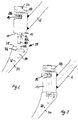
- Fig. 1
- eine Seitenansicht eines Teils des erfindungsgemäßen Werkzeugs;
- Fig. 2
- die Ankopplung des Griffs an dem Raspelkörper des Werkzeugs gemäß Fig. 1;
- Fig. 3
- den Griff nach dem Ankoppeln am Raspelkörper;
- Fig. 4
- eine Seitenansicht des Raspelkörpers und eines vom Raspelkörper abgenommenen Testadapters;
- Fig. 5
- den Raspelkörper mit aufgesetztem Testadapter;
- Fig. 6
- eine Seitenansicht des Raspelkörpers und eines mit dem Raspelkörper zusammenwirkenden Stirnfräsers;
- Fig. 7
- den Raspelkörper mit auf dem Raspelkörper lagerndem Stirnfräser;
- Fig. 8
- eine zweite Ausführungsform der Kopplung zwischen Raspelkörper und Griff in separiertem Zustand; und
- Fig. 9
- eine der Fig. 8 entsprechende Darstellung des Raspelkörpers mit angekoppeltem Griff.
- Die Fig. 1, 2 und 3 zeigen denjenigen Teil des Werkzeuges 2, der den Raspelkörper 30 und einen am Raspelkörper 30 lösbar befestigbaren Handgriff 4, 6 umfaßt. Der Raspelkörper 30 entspricht hinsichtlich seiner Form dem im Knochenhohlraum zu verankernden Prothesenschaft und verjüngt sich entsprechend zu seinem distalen Ende (nicht dargestellt) hin. Am proximalen Ende 39 des Raspelkörpers 30 ist eine Koppelhülse 10 lösbar befestigt, an der ein Stiel 6 befestigt ist, der an seinem oberen freien Ende einen Aufschlagteller 4 oder einen Anschluß eines motorischen Antriebs aufweist. Stiel 6 und Aufschlagteller 4 bilden den Handgriff, an dem zusätzlich ein weiterer Haltegriff 8 angesetzt werden kann. Wie in Fig. 1 dargestellt, verläuft die Längsachse des Stiels 6 mit geringem Parallelversatz fluchtend zur Längsachse 32 des Raspelkörpers, damit die vom Benutzer über den Handgriff auf den Raspelkörper 30 aufgebrachten Kräfte mit möglichst geringem Drehmoment wirken können.
- Wie insbesondere den Fig. 3 und 4 entnehmbar ist, besitzt der Raspelkörper 30 an seinem proximalen Ende eine ebene Stirnfläche 38, die unter einem vorgegebenen Winkel zur Längsachse 32 verläuft und eine Anlagefläche für an den Raspelkörper 30 ansetzbare oder ankoppelbare Teile des Werkzeugs besitzt. Die Stirnfläche 38 enthält in der in den Fig. 2 und 3 dargestellten Ausführungsform eine Quernut 40 zur Verdrehsicherung und zur Aufnahme der Schlagkräfte und ein von der Quernut 40 ausgehendes, zur Stirnfläche 38 senkrecht verlaufendes Sackloch 34, welches unmittelbar im Anschluß an die Quernut 40 eine Hinterschneidung 36 aufweist. Die an einem Ende des Handgriffs 4, 6 befestigte Koppelhülse 10 besitzt an ihrem unteren Ende eine ebene Auflagefläche 11 und einen Paßfederansatz 12, der in die Quernut 40 des Raspelkörpers eingreift, wenn die Anlagefläche 11 der Koppelhülse 10 sich gegen die Stirnfläche 38 des Raspelkörpers 30 anlegt. Durch die Koppelhülse 10 verläuft zentral ein Stift 20 mit einem unterhalb des Paßfederansatzes 12 liegenden Queransatz 22, der bei Drehung des zentralen Stiftes 20 sich in der Hinterschneidung 36 des Raspelkörpers 30 verankert und auf diese Weise die Koppelhülse mit dem Raspelkörper 30 verspannt. Zum Drehen des zentralen Stifts 20 ist ein Querzapfen 26 am Stift 20 befestigt, der durch eine entsprechende Nut 14 aus der Koppelhülse herausragt. Zum axialen Verspannen des Stifts 20 ist an dem Raspelkörper 30 abgewandten Ende des Stifts 20 eine Rändelschraube 28 vorgesehen, die auf einem Gewinde 24 des Stifts 20 läuft und den Stift in axialer Richtung gegen den Raspelkörper 30 verspannt, nachdem der Ansatz 22 die Hinterschneidung 36 hintergreift.
- In den Fig. 4 und 5 ist der schon in den Fig. 2 und 3 gezeigte Raspelkörper 30 dargestellt, wobei jedoch der Handgriff 4, 6 samt Koppelhülse 10 abgenommen ist und anstelle des Handgriffs 4, 6 ein sogenannter Testadapter 50 auf das proximale Ende 39 des Raspelkörpers 30 aufsetzbar ist. Der Testadapter 50 entspricht in seiner Form einem an den Prothesenschaft proximal anschließenden Teil der zu implantierenden Endoprothese. Da in der dargestellten Ausführungsform der Raspelkörper 30 beispielsweise dem Schaft einer Hüftendoprothese entspricht, so entspricht der Testadapter dem Kragen 52 sowie dem Hals 54 einer entsprechenden Prothese. Auf den Hals 54 ist noch ein Kopf (nicht dargestellt) aufsetzbar, so daß die Position der zu implantierenden Prothese simuliert werden kann, wenn der Raspelkörper 30 im Knochenhohlraum verbleibt und als Testschaft dient.
- Der Testadapter 50 besitzt in der dargestellten Ausführungsform einen Zapfen 56, der in das Sackloch 34 am proximalen Ende 39 des Raspelkörpers 30 einsetzbar ist. Vorgesehen ist außerdem ein Sicherungszapfen 58, der in eine Sicherungsbohrung 37 des Raspelkörpers 30 einsteckbar ist und ein Drehen des Testadapters 50 sowie eine Lockerung auf dem Raspelkörper verhindert.
- In den Fig. 6 und 7 ist der in den Fig. 1 bis 5 dargestellte Raspelkörper 30 gezeigt, der statt des Handgriffs 4, 6 bzw. statt des Testadapters 50 als Gegenlager für einen Stirnfräser 60 dient. Der Stirnfräser 60 besitzt an seiner unteren Stirnfläche 62 Schneiden 64, die radial über das proximale Ende des Raspelkörpers 30 hinausragen und zum Abfräsen des an den Raspelkörper anschließenden Knochenrandes dienen. Der Stirnfräser 60 besitzt an seiner Stirnfläche einen zentralen Zapfen 66, der mit ausreichemdem Spiel in das Sackloch 34 einführbar ist und dort drehbar lagert. Die Stirnfläche 38 und das Sackloch 34 bilden ein Auflager für den Stirnfräser 60, wenn der Raspelkörper 30 in dem Knochenhohlraum belassen ist, in den anschließend ein Prothesenschaft implantiert werden soll.
- Die Fig. 8 und 9 zeigen eine den Fig. 2 und 3 entsprechende weitere Ausführungsform der Koppelverbindung zwischen Raspelkörper 30 und Griff 6. Das proximale Ende des Raspelkörpers 30 besitzt in dieser dargestellten Ausführungsform eine plane Stirnfläche 38, die unter einem vorgegebenen Winkel zur Längsachse 32 des Raspelkörpers 30 verläuft. Senkrecht zur Stirnfläche 38 ist ein Sackloch 34 eingearbeitet, welches in der dargestellten Ausführungsform ein Gewinde 33 aufweist. Die Koppelhülse 10 besitzt an ihrem unteren Ende eine ebene Anlagefläche sowie einen zentralen Stift 70, der an seinem unteren Ende ein mit dem Innengewinde 33 des Sackloches 34 kooperierendes Außengewinde 74 aufweist. Am gegenüberliegenden Ende besitzt der zentrale Stift 70 einen Kopf 72, an dem der zentrale Stift 70 in das Innengewinde 33 des Sackloches 34 eingeschraubt und auf diese Weise befestigt werden kann. Quer zum Stift 70 verläuft in der Hülse 10 eine Sicherungsschraube 76 als Verliersicherung des Stiftes 70.
Claims (15)
- Werkzeug zum Implantieren einer Endoprothese in den Hohlraum eines menschlichen Knochens, mit einem Raspelkörper, welcher eine Form aufweist, die dem im Knochenhohlraum zu verankernden Prothesenschaft entspricht,
dadurch gekennzeichnet, daß am proximalen Ende des Raspelkörpers (30) ein Handgriff (4, 6) lösbar befestigbar ist. - Werkzeug nach Anspruch 1,
dadurch gekennzeichnet, daß ein Testadapter (50), welcher einem am Prothesenschaft proximal anschließenden Teil der zu implantierenden Endoprothese entspricht, anstelle des Handgriffs (4, 6) auf das proximale Ende (39) des Raspelkörpers (30) aufsetzbar ist. - Werkzeug nach Anspruch 2,
dadurch gekennzeichnet, daß der Testadapter (50) ein- oder mehrteilig ausgebildet ist. - Werkzeug nach einem der vorstehenden Ansprüche,
dadurch gekennzeichnet, daß der Raspelkörper (30) hinsichtlich seiner Form dem Schaft einer Hüftendoprothese entspricht, und daß der Testadapter (50) dem Kragen (52) und gegebenenfalls dem Hals (54) und gegebenenfalls dem Kopf der Hüftendoprothese entspricht. - Werkzeug nach einem der vorstehenden Ansprüche,
dadurch gekennzeichnet, daß anstelle des Handgriffs (4, 6) am proximalen Ende (30) des Raspelkörpers (30) ein den Raspelkörper (30) radial überragender Stirnfräser (60) aufsetzbar und drehbar lagerbar ist. - Werkzeug nach einem der vorstehenden Ansprüche,
dadurch gekennzeichnet, daß am proximalen Ende (39) des Raspelkörpers (30) ein Auflager (34, 38) für den Stirnfräser (60) vorgesehen ist. - Werkzeug nach Anspruch 6,
dadurch gekennzeichnet, daß das Auflager (34, 38) eine unter vorgegebenem Winkel zur Längsachse (32) des Raspelkörpers (30) verlaufende ebene Stirnfläche (38) enthält. - Werkzeug nach einem der vorstehenden Ansprüche:
dadurch gekennzeichnet, daß das Auflager (34, 38) senkrecht zur Stirnfläche (38) einen Lagerzapfen bzw. ein Sackloch (34) enthält, und daß an der Stirnfläche (62) des Stirnfräsers (60) ein entsprechendes Sackloch bzw. ein entsprechender Lagerzapfen (66) angeordnet ist. - Werkzeug nach einem der vorstehenden Ansprüche,
dadurch gekennzeichnet, daß die Stirnfläche (38) des Auflagers (34, 38) und die Stirnfläche (62) des Stirnfräsers (60) je ein Sackloch enthalten, in die ein separater Lagerzapfen einsetzbar ist. - Werkzeug nach einem der vorstehenden Ansprüche,
dadurch gekennzeichnet, daß die Befestigung des Handgriffs (4, 6) am Raspelkörper (30) mittels eines Bajonettverschlusses erfolgt. - Werkzeug nach einem der vorstehenden Ansprüche,
dadurch gekennzeichnet, daß die Befestigung des Handgriffs (4, 6) am Raspelkörper (30) mittels einer Schraubverbindung erfolgt. - Werkzeug nach einem der vorstehenden Ansprüche,
dadurch gekennzeichnet, daß eine Koppelhülse (10) vorgesehen ist, an der der Handgriff (4, 6) befestigbar ist, und daß durch die Koppelhülse (10) zentral ein Stift (20) hindurchgeführt ist, der in dem Sackloch (34) des Raspelkörpers (30) lösbar verschraubbar oder verriegelbar ist. - Werkzeug nach Anspruch 12,
dadurch gekennzeichnet, daß der Handgriff (4, 6) einen Stiel (6) enthält, der an der Koppelhülse (10) befestigt ist und sich parallel zur Längsachse (32) des Raspelkörpers (30) erstreckt. - Werkzeug nach Anspruch 1,
gekennzeichnet durch mehrere Raspelkörper (30) mit unterschiedlichem Hieb und/oder gegebenenfalls unterschiedlicher Form, die an dem Handgriff (4, 6) ankoppelbar sind. - Werkzeug nach Anspruch 14,
dadurch gekennzeichnet, daß mindestens einer der Raspelkörper (30) nach einem oder mehreren der Ansprüche 2 bis 13 ausgebildet ist.
Applications Claiming Priority (2)
| Application Number | Priority Date | Filing Date | Title |
|---|---|---|---|
| DE19604494A DE19604494A1 (de) | 1996-02-08 | 1996-02-08 | Werkzeug zum Implantieren einer Endoprothese |
| DE19604494 | 1996-02-08 |
Publications (1)
| Publication Number | Publication Date |
|---|---|
| EP0788773A1 true EP0788773A1 (de) | 1997-08-13 |
Family
ID=7784798
Family Applications (1)
| Application Number | Title | Priority Date | Filing Date |
|---|---|---|---|
| EP97101786A Withdrawn EP0788773A1 (de) | 1996-02-08 | 1997-02-05 | Werkzeug zum Implantieren einer Endoprothese |
Country Status (2)
| Country | Link |
|---|---|
| EP (1) | EP0788773A1 (de) |
| DE (1) | DE19604494A1 (de) |
Cited By (6)
| Publication number | Priority date | Publication date | Assignee | Title |
|---|---|---|---|---|
| WO2004089226A1 (de) * | 2003-04-11 | 2004-10-21 | Martin Nolde | Raspelaufsatz für ein motorgetriebenes chirurgisches handgerät |
| FR2867968A1 (fr) * | 2004-03-26 | 2005-09-30 | Ct Pulse Orthopedics Ltd | Instrumentation modulaire pour la preparation d'un fut femoral dans une prothese de hanche |
| EP1570802A3 (de) * | 2004-03-05 | 2006-06-07 | Zimmer Technology, Inc. | Justierbare Halterung für navigiertes Folgeelement |
| EP1759664A1 (de) * | 2005-08-30 | 2007-03-07 | DePuy Products, Inc. | Kit zur Verwendung in der orthopädischen Chirurgie |
| CN114423387A (zh) * | 2019-09-30 | 2022-04-29 | 舒克拉医疗 | 植入物取出器组件和植入物取出的方法 |
| DE102024118088A1 (de) * | 2024-06-26 | 2025-12-31 | Aesculap Ag | Vorrichtung zum Ausführen einer Resektion bei einem Oberschenkel- oder Unterschenkelknochen |
Families Citing this family (1)
| Publication number | Priority date | Publication date | Assignee | Title |
|---|---|---|---|---|
| DE102007052173B4 (de) | 2007-10-30 | 2012-01-12 | Kilian Kraus | Handhabungswerkzeug für ein medizinisches Implantat |
Citations (7)
| Publication number | Priority date | Publication date | Assignee | Title |
|---|---|---|---|---|
| US4306550A (en) * | 1980-02-06 | 1981-12-22 | Minnesota Mining And Manufacturing Company | Combination including femoral rasp and calcar facing reamer |
| US4601289A (en) * | 1985-04-02 | 1986-07-22 | Dow Corning Wright | Femoral trial prosthesis/rasp assembly |
| EP0548485A2 (de) * | 1991-12-20 | 1993-06-30 | Bristol-Myers Squibb Company | Anordnung mit chirurgischer Raspel |
| DE4243444A1 (de) * | 1992-12-22 | 1994-07-14 | Aesculap Ag | Raspel zur Vorbereitung einer Knochenöffnung |
| EP0619097A1 (de) * | 1993-04-07 | 1994-10-12 | SULZER Medizinaltechnik AG | Raspel und eine damit kuppelbares Griffteil zum Vorbereiten eines Röhrenknochens für den Einsatz einer Prothese |
| DE19501882A1 (de) * | 1994-05-06 | 1995-11-09 | Link Waldemar Gmbh Co | Medizinisches Instrument |
| FR2719464A1 (fr) * | 1994-05-09 | 1995-11-10 | Medinov Sa | Ensemble porte râpe fémorale. |
Family Cites Families (5)
| Publication number | Priority date | Publication date | Assignee | Title |
|---|---|---|---|---|
| DE3907256A1 (de) * | 1989-03-07 | 1990-09-20 | Orthoplant Endoprothetik | Knochenraspel |
| US5342362A (en) * | 1991-08-29 | 1994-08-30 | Zimmer Inc. | System and instrumentation for torsionally testing femoral rasp and hip stem implant including motion indicator |
| US5261915A (en) * | 1992-04-16 | 1993-11-16 | Scott M. Durlacher | Femur bone rasp with adjustable handle |
| DE4323873C2 (de) * | 1993-07-16 | 1996-07-18 | Eska Medical Gmbh & Co | Hohlschaftraspel |
| US5441501A (en) * | 1994-06-20 | 1995-08-15 | Zimmer, Inc. | Intermedullary rasp with detachable extension end |
-
1996
- 1996-02-08 DE DE19604494A patent/DE19604494A1/de not_active Withdrawn
-
1997
- 1997-02-05 EP EP97101786A patent/EP0788773A1/de not_active Withdrawn
Patent Citations (7)
| Publication number | Priority date | Publication date | Assignee | Title |
|---|---|---|---|---|
| US4306550A (en) * | 1980-02-06 | 1981-12-22 | Minnesota Mining And Manufacturing Company | Combination including femoral rasp and calcar facing reamer |
| US4601289A (en) * | 1985-04-02 | 1986-07-22 | Dow Corning Wright | Femoral trial prosthesis/rasp assembly |
| EP0548485A2 (de) * | 1991-12-20 | 1993-06-30 | Bristol-Myers Squibb Company | Anordnung mit chirurgischer Raspel |
| DE4243444A1 (de) * | 1992-12-22 | 1994-07-14 | Aesculap Ag | Raspel zur Vorbereitung einer Knochenöffnung |
| EP0619097A1 (de) * | 1993-04-07 | 1994-10-12 | SULZER Medizinaltechnik AG | Raspel und eine damit kuppelbares Griffteil zum Vorbereiten eines Röhrenknochens für den Einsatz einer Prothese |
| DE19501882A1 (de) * | 1994-05-06 | 1995-11-09 | Link Waldemar Gmbh Co | Medizinisches Instrument |
| FR2719464A1 (fr) * | 1994-05-09 | 1995-11-10 | Medinov Sa | Ensemble porte râpe fémorale. |
Cited By (10)
| Publication number | Priority date | Publication date | Assignee | Title |
|---|---|---|---|---|
| WO2004089226A1 (de) * | 2003-04-11 | 2004-10-21 | Martin Nolde | Raspelaufsatz für ein motorgetriebenes chirurgisches handgerät |
| US8021364B2 (en) | 2003-04-11 | 2011-09-20 | Martin Nolde | Rasp attachment for a motor-driven surgical hand-held device |
| EP1570802A3 (de) * | 2004-03-05 | 2006-06-07 | Zimmer Technology, Inc. | Justierbare Halterung für navigiertes Folgeelement |
| FR2867968A1 (fr) * | 2004-03-26 | 2005-09-30 | Ct Pulse Orthopedics Ltd | Instrumentation modulaire pour la preparation d'un fut femoral dans une prothese de hanche |
| EP1759664A1 (de) * | 2005-08-30 | 2007-03-07 | DePuy Products, Inc. | Kit zur Verwendung in der orthopädischen Chirurgie |
| US8048167B2 (en) | 2005-08-30 | 2011-11-01 | Depuy Products, Inc. | Orthopaedic implant kit, orthopaedic surgery kit and associated method |
| CN114423387A (zh) * | 2019-09-30 | 2022-04-29 | 舒克拉医疗 | 植入物取出器组件和植入物取出的方法 |
| US11660210B2 (en) * | 2019-09-30 | 2023-05-30 | Shukla Medical | Implant extractor assembly and method of implant extraction |
| DE102024118088A1 (de) * | 2024-06-26 | 2025-12-31 | Aesculap Ag | Vorrichtung zum Ausführen einer Resektion bei einem Oberschenkel- oder Unterschenkelknochen |
| DE102024118088B4 (de) * | 2024-06-26 | 2026-02-05 | Aesculap Ag | Vorrichtung zum Ausführen einer Resektion bei einem Oberschenkel- oder Unterschenkelknochen |
Also Published As
| Publication number | Publication date |
|---|---|
| DE19604494A1 (de) | 1997-08-14 |
Similar Documents
| Publication | Publication Date | Title |
|---|---|---|
| DE2838348C2 (de) | Vorrichtung zum Ausformen einer Knochenöffnung | |
| DE69431002T2 (de) | Flexible Reibahle für einen Knochenmarkkanal | |
| DE19713416B4 (de) | Führungsvorrichtung für ein Zwischenwirbelimplantat | |
| EP0554210B1 (de) | Bausatz für eine künstliche Hüftgelenkspfanne | |
| DE69819567T2 (de) | Orthopädische Schnittführung und Hülse | |
| EP2276422B1 (de) | Modulare femurkopfprothese | |
| EP0619990B1 (de) | Bausatz für eine künstliche Gelenkspfanne, insbesondere eine Hüftgelenkspfanne | |
| DE2834297C3 (de) | Vorrichtung zum Bearbeiten eines endseitig mit einer Prothesenkappe zu versehenden Knochens | |
| EP0228339A2 (de) | Bohrsystem zum Einbringen einer Endoprothese | |
| EP1284675A1 (de) | Vorrichtung mit einem knochenfräser | |
| DE102004051792B4 (de) | Chirurgisches Instrument mit einstellbarem rotatorischem Schneidwerkzeug | |
| DE2834295B2 (de) | Vorrichtung zum Herstellen einer sich vom stirnseitigen Endabschnitt eines Knochens konisch verjüngenden Mantelfläche | |
| DE10200690A1 (de) | Hilfsmittel zur Implantation einer Hüftgelenkendoprothese, sowie Verfahren für Handhabung derselben | |
| EP0327509A1 (de) | Chirurgisches Instrument zum Einsetzen von Hüftpfannen-Prothesen | |
| DE2830566A1 (de) | Vorrichtung zum ausformen einer knochenoeffnung im hueftbein zum einsetzen einer kuenstlichen gelenkpfanne | |
| EP0393608B1 (de) | Oberschenkelteil einer Hüftgelenk-Endoprothese | |
| DE3336004C2 (de) | Adapter für eine Knochen-Endoprothese | |
| DE69817923T2 (de) | Apparat zum lösbaren Anbringen eines Betätigungsmittels an einem chirurgischen Element oder Werkzeug | |
| EP0788773A1 (de) | Werkzeug zum Implantieren einer Endoprothese | |
| DE69220771T2 (de) | Vorrichtung zum Entfernen von chirurgischem Zement | |
| EP2666418B1 (de) | Chirurgisches Fräswerkzeug | |
| WO2001050977A1 (de) | Aufbaupfosten und befestigungseinrichtung für die zahnprothetik bzw. implantologie | |
| DE102024118088B4 (de) | Vorrichtung zum Ausführen einer Resektion bei einem Oberschenkel- oder Unterschenkelknochen | |
| DE69814528T2 (de) | Modulare Hüftprobeprothese für lange Schäfte | |
| EP0396520A1 (de) | Verankerungselement zum Halten eines Gelenkteils eines Fussgelenks oder anderer künstlicher Gelenke |
Legal Events
| Date | Code | Title | Description |
|---|---|---|---|
| PUAI | Public reference made under article 153(3) epc to a published international application that has entered the european phase |
Free format text: ORIGINAL CODE: 0009012 |
|
| AK | Designated contracting states |
Kind code of ref document: A1 Designated state(s): AT BE CH DE ES FR GB IT LI NL |
|
| 17P | Request for examination filed |
Effective date: 19980108 |
|
| 17Q | First examination report despatched |
Effective date: 20010820 |
|
| STAA | Information on the status of an ep patent application or granted ep patent |
Free format text: STATUS: THE APPLICATION IS DEEMED TO BE WITHDRAWN |
|
| 18D | Application deemed to be withdrawn |
Effective date: 20030812 |