EP0788808A2 - Cathéter préformé pour stimulateur cardiaque double chambre - Google Patents
Cathéter préformé pour stimulateur cardiaque double chambre Download PDFInfo
- Publication number
- EP0788808A2 EP0788808A2 EP97300841A EP97300841A EP0788808A2 EP 0788808 A2 EP0788808 A2 EP 0788808A2 EP 97300841 A EP97300841 A EP 97300841A EP 97300841 A EP97300841 A EP 97300841A EP 0788808 A2 EP0788808 A2 EP 0788808A2
- Authority
- EP
- European Patent Office
- Prior art keywords
- catheter
- atrial
- section
- electrodes
- heart
- Prior art date
- Legal status (The legal status is an assumption and is not a legal conclusion. Google has not performed a legal analysis and makes no representation as to the accuracy of the status listed.)
- Withdrawn
Links
- 230000001746 atrial effect Effects 0.000 claims abstract description 153
- 210000002620 vena cava superior Anatomy 0.000 claims abstract description 44
- 210000002837 heart atrium Anatomy 0.000 claims abstract description 33
- 229920002635 polyurethane Polymers 0.000 claims abstract description 7
- 239000004814 polyurethane Substances 0.000 claims abstract description 7
- 239000004721 Polyphenylene oxide Substances 0.000 claims abstract description 5
- 229920000570 polyether Polymers 0.000 claims abstract description 5
- 230000002861 ventricular Effects 0.000 claims description 54
- 230000033001 locomotion Effects 0.000 claims description 30
- 230000006641 stabilisation Effects 0.000 claims description 16
- 238000011105 stabilization Methods 0.000 claims description 16
- 239000007943 implant Substances 0.000 claims description 10
- 239000000463 material Substances 0.000 claims description 10
- 230000000638 stimulation Effects 0.000 claims description 10
- 239000008280 blood Substances 0.000 claims description 7
- 210000004369 blood Anatomy 0.000 claims description 7
- 230000000087 stabilizing effect Effects 0.000 claims description 7
- 238000003780 insertion Methods 0.000 claims description 6
- 230000037431 insertion Effects 0.000 claims description 6
- 210000000591 tricuspid valve Anatomy 0.000 claims description 6
- 230000000116 mitigating effect Effects 0.000 claims description 5
- 230000009977 dual effect Effects 0.000 claims description 4
- 230000004936 stimulating effect Effects 0.000 claims 1
- 230000000747 cardiac effect Effects 0.000 abstract description 18
- 230000028161 membrane depolarization Effects 0.000 abstract description 8
- 230000002441 reversible effect Effects 0.000 abstract description 5
- 230000029058 respiratory gaseous exchange Effects 0.000 abstract description 4
- 239000000560 biocompatible material Substances 0.000 abstract 1
- -1 for example Substances 0.000 abstract 1
- 210000005003 heart tissue Anatomy 0.000 description 16
- 239000004020 conductor Substances 0.000 description 12
- 230000006870 function Effects 0.000 description 11
- 238000000034 method Methods 0.000 description 11
- 238000009413 insulation Methods 0.000 description 9
- 230000007246 mechanism Effects 0.000 description 9
- 210000001519 tissue Anatomy 0.000 description 9
- 238000009998 heat setting Methods 0.000 description 6
- 230000001976 improved effect Effects 0.000 description 6
- 230000000241 respiratory effect Effects 0.000 description 6
- 230000001684 chronic effect Effects 0.000 description 4
- 230000008602 contraction Effects 0.000 description 4
- 230000003205 diastolic effect Effects 0.000 description 4
- 229920001971 elastomer Polymers 0.000 description 4
- 239000000806 elastomer Substances 0.000 description 4
- 210000003205 muscle Anatomy 0.000 description 4
- 230000004213 regulation of atrial cardiomyocyte membrane depolarization Effects 0.000 description 4
- 208000027418 Wounds and injury Diseases 0.000 description 3
- 210000005242 cardiac chamber Anatomy 0.000 description 3
- 230000006835 compression Effects 0.000 description 3
- 238000007906 compression Methods 0.000 description 3
- 238000001514 detection method Methods 0.000 description 3
- 230000000694 effects Effects 0.000 description 3
- 230000005284 excitation Effects 0.000 description 3
- 206010016654 Fibrosis Diseases 0.000 description 2
- 230000015556 catabolic process Effects 0.000 description 2
- 238000006731 degradation reaction Methods 0.000 description 2
- 238000005516 engineering process Methods 0.000 description 2
- 230000002708 enhancing effect Effects 0.000 description 2
- 230000004761 fibrosis Effects 0.000 description 2
- 238000007667 floating Methods 0.000 description 2
- 238000012423 maintenance Methods 0.000 description 2
- 238000005457 optimization Methods 0.000 description 2
- 229920000642 polymer Polymers 0.000 description 2
- 239000000725 suspension Substances 0.000 description 2
- 208000033988 Device pacing issue Diseases 0.000 description 1
- 239000006096 absorbing agent Substances 0.000 description 1
- 238000010521 absorption reaction Methods 0.000 description 1
- 230000009471 action Effects 0.000 description 1
- 238000004873 anchoring Methods 0.000 description 1
- 210000001008 atrial appendage Anatomy 0.000 description 1
- 230000009286 beneficial effect Effects 0.000 description 1
- 230000015572 biosynthetic process Effects 0.000 description 1
- 230000037237 body shape Effects 0.000 description 1
- 239000002775 capsule Substances 0.000 description 1
- 210000004413 cardiac myocyte Anatomy 0.000 description 1
- 239000011248 coating agent Substances 0.000 description 1
- 238000000576 coating method Methods 0.000 description 1
- 230000007812 deficiency Effects 0.000 description 1
- 238000013461 design Methods 0.000 description 1
- 230000003292 diminished effect Effects 0.000 description 1
- 239000013536 elastomeric material Substances 0.000 description 1
- 238000004070 electrodeposition Methods 0.000 description 1
- 238000005265 energy consumption Methods 0.000 description 1
- 239000012530 fluid Substances 0.000 description 1
- 230000001939 inductive effect Effects 0.000 description 1
- 208000014674 injury Diseases 0.000 description 1
- 239000012774 insulation material Substances 0.000 description 1
- 230000010354 integration Effects 0.000 description 1
- 230000007774 longterm Effects 0.000 description 1
- 238000004519 manufacturing process Methods 0.000 description 1
- 239000002184 metal Substances 0.000 description 1
- 238000012986 modification Methods 0.000 description 1
- 230000004048 modification Effects 0.000 description 1
- 210000004165 myocardium Anatomy 0.000 description 1
- 230000007383 nerve stimulation Effects 0.000 description 1
- 210000003105 phrenic nerve Anatomy 0.000 description 1
- 230000001902 propagating effect Effects 0.000 description 1
- 230000034225 regulation of ventricular cardiomyocyte membrane depolarization Effects 0.000 description 1
- 230000000284 resting effect Effects 0.000 description 1
- 230000033764 rhythmic process Effects 0.000 description 1
- 210000005245 right atrium Anatomy 0.000 description 1
- 210000005241 right ventricle Anatomy 0.000 description 1
- 230000035945 sensitivity Effects 0.000 description 1
- 238000000926 separation method Methods 0.000 description 1
- 238000007493 shaping process Methods 0.000 description 1
- 230000035939 shock Effects 0.000 description 1
- 230000003595 spectral effect Effects 0.000 description 1
- 210000000278 spinal cord Anatomy 0.000 description 1
- 239000003381 stabilizer Substances 0.000 description 1
- 230000002459 sustained effect Effects 0.000 description 1
- 238000002560 therapeutic procedure Methods 0.000 description 1
- 210000000115 thoracic cavity Anatomy 0.000 description 1
- 230000008733 trauma Effects 0.000 description 1
- 230000000007 visual effect Effects 0.000 description 1
- 239000002699 waste material Substances 0.000 description 1
Images








Classifications
-
- A—HUMAN NECESSITIES
- A61—MEDICAL OR VETERINARY SCIENCE; HYGIENE
- A61N—ELECTROTHERAPY; MAGNETOTHERAPY; RADIATION THERAPY; ULTRASOUND THERAPY
- A61N1/00—Electrotherapy; Circuits therefor
- A61N1/02—Details
- A61N1/04—Electrodes
- A61N1/05—Electrodes for implantation or insertion into the body, e.g. heart electrode
- A61N1/056—Transvascular endocardial electrode systems
-
- A—HUMAN NECESSITIES
- A61—MEDICAL OR VETERINARY SCIENCE; HYGIENE
- A61N—ELECTROTHERAPY; MAGNETOTHERAPY; RADIATION THERAPY; ULTRASOUND THERAPY
- A61N1/00—Electrotherapy; Circuits therefor
- A61N1/02—Details
- A61N1/04—Electrodes
- A61N1/05—Electrodes for implantation or insertion into the body, e.g. heart electrode
- A61N1/056—Transvascular endocardial electrode systems
- A61N1/0563—Transvascular endocardial electrode systems specially adapted for defibrillation or cardioversion
Definitions
- the present invention relates to a catheter configuration for a dual-chamber pacemaker system.
- the configuration employs a heat-settable polyurethane catheter having a plurality of electrodes, wherein the catheter is formed to provide stable support to the atrial electrodes and ensure proper contact of the atrial electrodes on the inner wall of the atrium, while also providing stress relief to absorb stresses on the configuration occasioned by respiration and contraction of the bulk cardiac complex.
- Reenstierna's configuration does relieve longitudinal motion and deformation stresses induced by respiration at the superior vena cava site. However, it is clear that Reenstierna's configuration does not adequately reduce ventricular-induced stresses. Reenstierna further expresses the potential need to strengthen only the section of the catheter disposed along the atrial wall, but fails to recognize that in order to provide adequate counter forces that oppose the forces applied to the catheter along the atrial wall, the loop stabilization means being strengthened only in the section of the catheter along the atrial wall would be inappropriate and ineffective.
- U.S. Patent No. 4,374,527, to Iversen discloses a body-stimulation lead having multiple lobes formed therein for absorbing body forces by deforming longitudinally in compression and elongation to minimize the influence of forces on electrodes positioned on other sections of the catheter.
- the configuration taught by Iversen is only useful in mitigating longitudinal forces and is not effective for holding purposes in the shaped region and for reducing horizontal forces, such as those induced by respiration. There is no means provided in Iversen to hold the catheter in place, especially in a position within the atrial chamber of the heart.
- U.S. Patent No. 4,394,886, to Hughes discloses a helical lead for atrial leads only.
- the spiral loops of the catheter are disposed in the superior vena cava and purportedly provide stabilization of atrial electrodes only.
- None of the prior art systems discussed provides a single-catheter, dual-chamber pacing and sensing system that includes stress relief mechanisms that cooperate with stabilization mechanisms to ensure proper electrode contact with the desired areas within a specific chamber of the heart, while maintaining the desired contact in spite of movements and stresses on the catheter occasioned by remote and cardiac bulk complex movements.
- the present invention provides an improved apparatus that overcomes the deficiencies of known single-catheter systems with respect to providing proper electrode contact while mitigating the effects of stresses placed on the catheter by both locally and remotely induced motional forces on the catheter.
- the present invention uses a single preformed catheter which is formed to provide cantilevered support and stabilization by providing distributed pressure stabilizing contact points in the superior vena cava, preformed atrial wall conformity to assure atrial electrode contact and increased pliancy of the catheter distal to the atrial electrodes, thereby providing stress relief above and below the tricuspid valve to mitigate motion of the atrial electrodes and ventricular electrode during the cardiac and respiratory cycle, while positioning the atrial and ventricular electrodes to optimize pacing and sensing.
- a further object of the present invention is to reduce the effect of external forces on the atrial electrodes using the catheter configuration to mitigate the forces.
- An additional object of the present invention is to stabilize the position of the atrial electrodes using catheter configurations that are supported by their position and shape within the superior vena cava.
- a still further object of the present invention is to provide improved pacing and sensing using electrodes that face only the wall of the atrium in which they are disposed.
- Another object of the present invention is to isolate the atrial electrodes from ventricularly induced motion by providing a catheter having greater pliancy in a portion that is distal of the atrial electrodes and that extends through the tricuspid valve.
- the present invention provides a single catheter for pacing and sensing both the atrial and ventricular chambers of the heart, comprising: preformed stabilization configuration of the catheter disposed primarily in the superior vena cava; atrial electrodes disposed on an atrial section of the catheter and being arranged to conform to the atrial wall and being held in proximity to the atrial wall by the stabilization configuration of the catheter disposed primarily in the superior vena cava; a stress relief portion of the catheter disposed between the atrial electrodes and the distal end of the catheter termination in the ventricular chamber of the heart; and a ventricular electrode disposed at the distal end of the catheter for pacing and sensing the ventricular chamber of the heart.
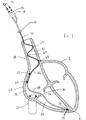
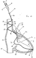
- Figure 1 is a cross-sectional view of one embodiment of the present invention employing a plurality of curved portions of a catheter in the superior vena cava.
- the catheter 70 is positioned in the heart 1 by passing the catheter 70 through the superior vena cava 18.
- Implant of the catheter 70 in the heart 1 is normally accomplished using known techniques, such as, for example, using a stylet 10 to straighten the preformed catheter 70 for insertion via the superior vena cava 18.
- the stylet 10 is removed from the catheter 70 and the catheter 70 assumes the preformed shape according to any of the exemplary embodiments described herein.
- the catheter 70 includes connectors 12, 14 for providing electrical connection between the electrodes 22, 24 and an implanted medical device (not shown), such as, for example, a pacemaker.
- the catheter 70 may also optionally include a tie-down stabilizer and position indicator 16 which is useful in positioning the catheter 70 during implant and stabilizing catheter position post-implant.
- the catheter 70 also includes tines 38 and/or an active fixation screw 40 at a distal end thereof to provide additional stability to the implanted catheter and to ensure proper positioning of a ventricular electrode 41.
- the catheter 70 is made of biocompatible insulative materials that are heat-settable to a desired configuration and provide stable memory, i.e., they return to the preformed shape once they have been implanted and after the stylet 10 has been removed.
- biocompatible heat-settable material is polyether polyurethane, available from Polymer Technology Corporation under the name BioSpan. Details of the catheter configuration will be discussed below with respect to Figure 10.
- the catheter 70 of the present invention facilitates permanent pacing and sensing in two chambers of the heart, such as, for example, the right atrium 26 and the right ventricle 28. It will, of course, be understood that the principles of catheter formation and placement discussed herein with respect to the present invention may be equally applicable to unipolar, bipolar and multiple catheter configurations that are disposed in any selected chambers of the heart, as required.
- multiple curved portions 64, 66 of the catheter 70 are disposed in the superior vena cava 18, and are preformed to provide distributed pressure stabilizing contact points along the inner walls of the superior vena cava 18, where the curved portions press outwardly against the superior vena cava 18.
- the last curved portion 66, in conjunction with the other curved portions 64, is formed to provide cantilevered support to a portion 46 of the catheter 70 wherein the electrodes 22, 24 are disposed.
- the preformed shape of the catheter 70 in the portion 46 is formed to provide conformity to the atrial wall 34, thereby assuring atrial electrode contact.
- the catheter 70 is also provided with a relatively pliant portion 44 which extends from an area distal of the electrodes 22, 24 but proximal the tricuspid valve 30. Forming the portion 44 in a manner such that it is more flexible or pliant than the rest of the catheter 70 provides stress relief above and below the tricuspid valve 30 and mitigates motion of the atrial electrodes 22, 24 and ventricular electrode 41 during the cardiac cycle and respiratory cycle.
- the catheter 70 should have the same general pliancy down through the location of the electrodes 22 and 24, and have a relatively greater pliancy in the portion 44 below the electrodes 22 and 24.
- Atrial electrode placement for optimizing pacing and sensing is achieved by disposing the atrial electrodes 22, 24 principally toward the atrial wall 34. Maintaining this electrode position is, therefore, also an important object.
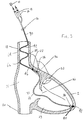
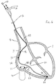
- the embodiments shown in Figures 1 and 2 depict atrial lateral wall placement of the atrial electrodes 22, 24. Anterior wall placement of the atrial electrodes 22, 24 is also facilitated, if required, as shown in Figure 3.
- the catheter's 70 superior vena cava contact points 64, 66 provide a cantilevered base to stabilize the atrial conformal section of the catheter 70 along the lateral atrial wall 34 or anterior atrial wall 36, as required.
- Providing a relatively rigid cantilevered base allows the use of a stress-relief shape and a portion of greater pliancy 44 of the catheter 70 below the atrial electrodes 22, 24 and in the ventricular section of the lead as cooperative aids to achieve atrial electrode stability.
- the atrial section 46 of the catheter 70 is held in place from above the superior vena cava 18 and isolated from the dominant ventricular motion of the heart 1 by the more flexible and pliant portion 44 of the catheter 70 below the atrial electrodes 22, 24.
- the curved portions 64, 66 of the catheter 70 of the present invention provide cantilevered support as a stabilization and holding mechanism to ensure the maintenance of optimal electrode positioning.
- Using the combined cantilevered support of the catheter 70 in an area 46 above and including the atrial electrodes 22, 24 and a section below the atrial electrodes 44 having greater pliancy and flexibility allows for mitigation of both respiratory and other body motions and the motions associated with cardiac rhythms.
- Respiratory motion induced from the diaphragm places longitudinal forces on the bulk cardiac complex. This respiratory-induced motion tends to slightly elongate the cardiac structure during inspiration and shorten the cardiac structure during expiration.
- Diaphragmatic motion also induces motion of the bulk cardiac complex relative to the chest cavity which places stretching forces at the site of the catheter 70 in the superior vena cava 18.
- the major longitudinal forces that modulate the dimensions of the bulk cardiac complex are absorbed in the catheter section 44 below the atrial electrodes 22, 24.
- Dimensional modulation of the atrial chamber 26 from respiratory motion is absorbed in the arm of the cantilevered section 46 subtending the atrial wall 34 and the wall of the superior vena cava 18. It is also important to note that the atrial electrodes 22, 24 only need to provide contact or very close contact to the atrial wall 34 during the diastolic period or resting state of the entire cardiac complex.
- the diastolic period is a "settle-down" time in which the catheter 70 has time to reconform to the end diastolic shape of the atrial wall 34 and be in a position to be ready to stimulate the atrium 26 via signals from the pacemaker if the SA nodal rate is below the pacemaker escape rate. Accordingly, if a stimulus is required, the heart 1 has reached its most relaxed state, and the atrial electrodes 22, 24 have had time for repositioning and stabilization against atrial cardiac tissue if they have been displaced during the preceding cardiac systole.
- the SA node provides the excitation to initiate systole of the atrium 26 rather than requiring an artificial pacing stimulus
- the resulting atrial wall 34 contraction would be directed toward the atrial electrodes 22, 24 and enhance contact for sensing of the atrial depolarization signal, which, in turn, provides synchronization of the ventricular stimulus delivered from the pacemaker. Even if the atrial electrodes were temporarily displaced from the atrial wall 34 during systole, contact with atrial tissue is not required for sensing atrial depolarization.
- the present invention provides a unipolar catheter configuration wherein atrial electrode contact for atrial stimulation is stabilized at the end diastolic period when it is needed, and if not needed, SA excitation of the atrium 26 will cause atrial wall 34 motion most likely in a direction to assist atrial sensing. If electrode contact is lost during atrial systole, sensing may still be accomplished from the electrodes 22, 24 in a blood pool location.
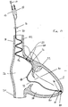
- the catheter configuration depicted in Figure 2 is the same as that shown in Figure 1, but providing a pliant section 44 that has additional length to facilitate greater absorption of cardiac-induced motions.
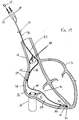
- the catheter configuration shown in Figure 3 is one in which the atrial electrodes 22, 24 are positioned to be along the anterior wall 36 of the atrium 26. It is noted that the pliant section 44 of the configuration shown in Figure 3 may be provided with additional length as shown in Figure 2. The length of the pliant section 44, required in a particular application, is determinable by one of ordinary skill.
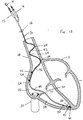
- the catheters depicted in these figures are similar to those depicted in Figures 1-3, with the exception that the "holding" portion 42 of the catheter 70 contained within the superior vena cava 18 is of a generally helical or spiral shape.
- the cantilevered support structure employs a substantially spiral shape in the superior vena cava 18 to provide stability of the conformal atrial section 46 of the catheter 70.
- the spiral configuration portion 42 of the catheter 70 disposed in the superior vena cava 18 is used only for holding purposes and for direct deformation with and during deformation of the superior vena cava 18.
- FIG. 5 is similar to Figure 3 in that it positions the atrial electrodes 22, 24 along the anterior atrial wall 36 of the atrium 26.
- the configuration shown in Figure 5 uses a spiral holding configuration in the superior vena cava 18 as shown in Figure 4.
- the superior vena cava region 42 of the catheter 70 relies on a preformed "U"-shape, or lobe, having large enough dimensions to apply holding forces at one location in the superior vena cava 18 exit area, while providing opposing forces at the section 46 containing the atrial electrodes 22, 24 disposed against the atrial wall 34.
- a single reverse bend is employed at the superior vena cava exit to provide a fulcrum for lever action against the section of the catheter proximal to the curved portion that traverses and contacts the opposite wall of the superior vena cava 18.
- This configuration also employs control of the pliancy and stress relief bends below the atrial section 46 of the catheter 70 as described above with respect to Figures 1-5. It is also noted that the single curved configuration shown in Figure 6 is equally applicable to applications which require atrial electrode placement along the anterior wall of the atrium.
- Figure 7 shows another embodiment of the present invention in which two preformed arms 48 are shown splayed away and angularly positioned, preferably at angles of 120° from the main catheter body. Each arm is also preferably separated from the other by an angle of 120°.
- the arms 48 in combination with the preformed catheter 70 provide a balanced three-point stabilizing mechanism for the base of the cantilevered section 46 of the catheter 70 disposed along the atrial wall 34. It will be understood that means for compressing the arms 48 next to the catheter body 70 during insertion into the venous system will be required and that preforming the arms 48 using the same materials as used to house the catheter body 70 will provide sufficient spring-loading so that the arms 48 can perform their desired function.
- compression means include, for example, a tie strand that can be pull-released at the proximal connector 12 end of the catheter following insertion of the catheter 70, a biocompatible dissolvable restraint that releases the splayed projections 48 upon sustained contact with blood, or simple manual deformation of the projections 48 for insertion via a catheter introducer.
- a tie strand that can be pull-released at the proximal connector 12 end of the catheter following insertion of the catheter 70
- a biocompatible dissolvable restraint that releases the splayed projections 48 upon sustained contact with blood
- simple manual deformation of the projections 48 for insertion via a catheter introducer simple manual deformation of the projections 48 for insertion via a catheter introducer.
- a minor projection or prominence 50 in the region of the catheter body 70 that houses the atrial electrodes 22, 24.
- a minor projection 50 may be preformed into the catheter 70 to enhance proximity of the electrode 22 to the atrial wall 60.
- the projection 50 may be formed in the catheter body 70 at the electrode site 22 during heat-setting of the elastomer insulation of the catheter 70 as a whole.
- the structure shown in Figure 9 may be employed.
- a rigid section 50 located between the electrodes 22, 24 provides the advantages of the projection or prominence discussed with respect to Figure 8, for a two-electrode configuration. This configuration enhances projection of the two tangent points of the catheter body 70 on the atrial wall 60 site of each electrode 22, 24.
- holding forces are provided at the wall of the superior vena cava 18 to insure that modest pressure is maintained on the electrodes 22, 24 that are placed lower on the catheter 70 and facing the atrial wall 34 or 36 (i.e., lateral or anterior atrial walls, respectively).
- a modest bend 72 or multiple bends 74 are preformed to absorb and mitigate forces that tend to displace the conformal atrial section 46 of the catheter 70.
- the ventricular section 44 of the catheter 70 also requires sufficient pliancy or flexibility and/or stress release bends 74 to prevent excess motion relative to the ventricular electrode 41, to prevent perforation of the ventricular electrode 41 through the ventricular muscle during systole and to provide stable anchoring at the distal end of the catheter 70 to prevent dislodging of the ventricular electrode 41.
- Fixation of the distal end of the catheter 70 using passive tines 38 and/or active screw mechanisms 40 provides additional insurance against post-implant dislodging of the ventricular electrode 41 and aids in stabilizing of the entire complex for long-term, chronic, dual-chamber pacing.
- the current trend toward use of small diameter catheters may not be necessary for dual-chamber pacing when only one catheter is required, as in the present invention.
- Larger diameter catheters are useful for dispersing the forces against the cardiac tissue, to allow greater control of the resiliency of various portions of the catheter, and to aid positional stability via the inherently larger frictional forces opposing motion at the various catheter/tissue interfaces or points of contact.
- a visual indicator 16 may be disposed on the proximal section 42 of the catheter 70 as shown in Figures 1-7.
- the indicator 16 is used in combination with the straightening stylet 10 during the implant procedure to provide an indication of the angular orientation of the catheter 70 within the heart chamber prior to deployment of the preformed shape upon removal of the stylet 10.
- the design of the elements of the catheter body 70 for forming and maintaining the desired permanent shape is important to provide the attributes discussed above with respect to the present invention.
- a preferred methodology is to employ insulative materials that are heat-settable to the desired configuration and the provide stable memory for returning the catheter 70 to the desired shape after the stylet 10 has been removed, post implant.
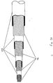
- two conductors are required for pacing and sensing of both chambers. Referring now to Figure 10, the two conductors 56 are space wound coaxial coil conductors. A double layer of insulation 54 is also required as shown in Figure 10.
- the insulative material is preferably a biocompatible, heat-settable, elastomeric material, such as, for example, heat-settable polyether polyurethane, available under the name BioSpan, from Polymer Technology Corporation.
- a preferred method of constructing the catheter body is to vertically extrude the polyurethane insulation or other biocompatible elastomer directly onto the individual coils and then slide the smaller coated coil into the larger coated coil prior to heat-setting the assembly. Pre-stressing the conductor coils prior to coating is an optional procedure that aids the memory of shape following final heat-setting of the assembly. Control of the thickness of the insulation material aids in control of the desired pliancy and memory of the assembly.
- Heat-setting following the assembly of the two coils also ensures cooperative memory of the individual insulative layers.
- Other methods of manufacturing the catheter may also be employed, including heat-settable extruded elastomer tubing for insulation. Using preformed conductor coils would also aid control of pliancy and memory of the desired shape.
- Electrode optimization is also an important consideration in enhancing system performance. Electrode optimization aids contact with cardiac tissue, minimizes cardiac tissue trauma, maximizes detection of cardiac signals and minimizes pacing energy requirements.
- the ventricular electrode 41 of the present invention is preferably fixed using passive tines 38 and/or an active fixation screw 40.
- an active fixation screw 40 it is preferred to utilize a guidewire or screwdriver-type mechanism, as described in U.S. Patent No. 4,217,913 to Dutchers, the disclosure of which is incorporated by reference herein in its entirety. This method allows preforming the entire assembly to achieve the desired memory and pliancy of the catheter. Other methods that require turning of the catheter or an internal section of the catheter are not suitable for use with the present invention, as this has serious drawbacks with respect to maintaining the proper orientation of the preformed catheter in the heart chamber.
- electrodes used for both sensing and pacing of cardiac tissue should be relatively small.
- very small electrodes deliver higher current density to excitable cardiac tissue for a given level of absolute current employed, as compared to relatively larger electrodes.
- Small electrodes also lower the excitation energy thresholds required to stimulate cardiac muscle, thereby minimizing the energy consumption required during pacing.
- very small electrodes are ideally suited for sensing cardiac depolarization, as described in my earlier U.S. Patent No. 5,127,403, the disclosure of which is incorporated by reference herein in its entirety.
- the depolarization wavefront dimensions in cardiac tissue are on the order of 1 mm or less, and contacting electrodes of similar size are theoretically ideal.
- Pacing thresholds also elevate chronically, when employing small electrodes due to tissue fibrosis at the electrode site. The fibrosis effectively increases the size of the virtual electrode formed by the combined metallic electrode and the non-excitable fibrous capsule. Because of the technical conflicts noted above with respect to small electrodes, electrode surface areas of smaller than about 4 mm 2 have been determined by historical empirical experience to be problematic for permanent pacing electrodes.
- Enhancement of detection of atrial depolarization and the pacing function in the atrial chamber also requires consideration of electrode shape. Among these considerations is the desire to enhance the probability of maintaining contact with the excitable cardiac tissue for pacing, and to optimize the shape to enhance detection of the propagating depolarization event.
- the electrode In addition to forming a projection or prominence in the preformed catheter as described above with respect to Figures 8 and 9, in order to maximize the probability of atrial wall contact, the electrode should protrude beyond the mean diameter of the catheter such that the electrode presses into cardiac tissue. This feature is illustrated in Figures 11 and 12. Another consideration is the variable terrain of the pectinate muscles in some areas of the interior wall of the atrium.
- This non-uniform surface containing many peaks and valleys dictates either using multiple electrodes or one electrode designed with dimensions and shape factors that take into account the irregularities of the inner wall surface of the atrium.
- the pectinate muscle typically has valleys having depths in the range of 2 to 3 mm and widths in the range of 2 to 3 mm.
- the exposed metal of the electrodes 22 should not completely encircle the catheter 70 because the back side, i.e., the side facing away from the inner wall 58 of the atrial wall 60, would waste the pacing current delivered into the blood pool. Furthermore, back-side exposure of the electrode 22 to the reduced field strength depolarization signal in the blood pool compared to the strength at the contact point averages down the resultant amplitude of the signal as observed only on the side of the electrode 22 facing the cardiac tissue 58.
- the electrode 22 surrounds a portion of the catheter 70, but shaped so as not to substantially increase the overall catheter diameter any greater than the protrusion dimension of the electrode 22 in the direction of the atrial wall as shown in Figures 11 and 12.
- the back-side of the electrode is formed into a ring that fully surrounds the outer conducting coil and is crimped in a place along the edges 64 during assembly prior to application of a final coat or sleeve 54 over the catheter 70 that insulates both the back-side facing away from the cardiac tissue 58 and the crimp area 64.
- the most important consideration in mechanical electrode attachment is to provide assurance against back-side exposure of the electrode to the blood pool and adequate mechanical fixation of the electrode 22 to the catheter body 70 to prevent accidental loosening and escape from the catheter body.
- both electrodes 22, 24 are shown deployed in the atrial chamber 26.
- Clinical experience may provide the statistical evidence to determine whether one or two electrodes are optimum.
- Both atrial electrodes 22, 24 shown in Figures 1-7 are mechanically and electrically connected to the outer conductor coil used to transport atrial pacing signals to the electrode from the pacemaker and atrial signals from the electrode to the pacemaker. It is known to those in the art that each electrode's performance for both pacing and sensing is degraded by the other electrically parallel, but spatially separated, electrodes. The current density for pacing at each electrode site is diminished by a factor of two, given a constant current source and equal surface areas, since current is equally distributed to both electrodes.
- Degradation of sensing also occurs with use of an electrically parallel electrode pair. This degradation occurs because the atrial depolarization wave front passes each electrode at different times and loading by the electrode at the inactive site attenuates the signals present at the alternate electrode site of depolarization activity.
- the atrial signal to far-field ventricular signal ratio is degraded if the electrode separation is such that both electrodes simultaneously observe like amplitude and phase ventricular signals.
- General attenuation of the atrial signals can be accommodated by using increased sensitivities in the atrial sensing electronics. Atrial to ventricular signal ratios can also be improved using atrial sensing filters tuned to the spectral content of atrial signals as developed on small surface area contact electrodes or electrodes proximate to cardiac tissue.
- the single atrial electrode may indeed provide the most elegant configuration for single-catheter, dual-chamber pacing systems.
- the additional ventricular electrode 38 may be a ring electrode. Ring electrodes and their characteristics are well-known in the art and the particular size and positioning of the electrode will be determinable by one of ordinary skill in the art in view of the present disclosure.
- Pacemaker systems are generally defined as being unipolar or bipolar. As such, both single chamber pacing with one lead or dual chamber pacing with two leads can be configured to be either unipolar or bipolar.
- Unipolar systems use the pacemaker case as one of the electrical poles that, in combination with the pacing electrode on a catheter, forms a complete electrical circuit from the pacing system through the body tissue and return.
- the return electrode is housed on the lead as a second electrode to serve as the return electrical path instead of using the metallic pacemaker housing.
- pacemaker systems have been developed but provide mixed unipolar or bipolar functionality. Additionally, such systems may also be reversible between which of the two poles serves as the "return" path. Systems having this reversible feature are called polarity-programmable.
- the negative pole i.e., negative pulse polarity
- a full bipolar version of the single catheter includes four conductors 56 (see Figure 20) for bipolar sensing and pacing in both heart chambers 26, 28.
- Four layers of insulation 54 are also required for a full dual bipolar system and three conductors and layers of insulation (not shown) are required for mixed systems that are unipolar in the ventricular chamber 28 and bipolar in the atrium 26.
- a preferred method of constructing the catheter body 70 is to vertically extrude polyether polyurethane insulation or other biocompatible elastomer directly on to each of the individual coils 56 and then slide the smaller coils into the longer coated coils prior to heat-setting the catheter in the desired shape and configuration.
- bipolar and unipolar configurations are contemplated.
- thinner conductors would be used to pace and sense on one unipolar electrode in the ventricle, pace unipolar parallel on a pair of electrodes in the atrium and sense bipolar on the same pair of atrial electrodes. Switching between parallel unipolar atrial pacing and bipolar atrial sensing may be accomplished in the pacemaker electronics.
- Unipolar pacing and sensing in the ventricle in combination with parallel unipolar pacing in the atrium and differential bipolar sensing in the atrium may provide the best and most reliable system for delivering dual chamber pacing therapy. It should be noted that for atrial pacing that electrodes should be spaced in the range of 0.5 to 1 cm rather than 1 to 3 mm. Sensing is known to be reliable in this range for floating electrodes and even more reliable in this range for with close proximity to the atrial wall. The pacing function is of more critical concern and dimensioning should favor optimizing for that function.
- the location of electrodes is less critical. If, however, both pacing and sensing is the desired function, the anterior wall 36 provides the best location for the electrodes, as shown in Figures 3, 5 and 15, for avoidance of phrenic nerve stimulation, as the best location to trap the catheter against angular rotation and the preferred location to prevent electrode suspension caused, for example, by bridging of the catheter across the cavity of the atrial appendage with the catheter located medial to the anterior wall 36.
- improved stability of the pacing function can be achieved when using any suitable pacing catheter having at least two electrodes by using bipolar sensing in conjunction with parallel unipolar pacing.
- Switching between bipolar sensing and parallel unipolar pacing can be accomplished by providing switchable electronics in the pacemaker associated with the catheter.
- the instant inventor has found that using switchable electronics to switch between bipolar sensing and parallel unipolar pacing improves the stability of the pacing, at least in part, by reducing the possibility of degraded functioning due to electrode suspension caused by bridging of the catheter along the interior wall of the heart.
- switchable electronics to achieve bipolar sensing and parallel unipolar pacing is not limited to use in connection with the particular catheter disclosed herein, but may be used with any known suitable pacing catheter to increase the operational stability thereof in one or more chambers of the heart.
- the beat by beat uncertainty of which electrode is closest to active tissue can be accommodated by delivery of a bipolar stimulus of one polarity on the pair of electrodes followed immediately by a reverse polarity stimulus.
- a bipolar stimulus of one polarity on the pair of electrodes followed immediately by a reverse polarity stimulus.
- this double polarity stimulus it is assured that the electrode with the best instantaneous proximity to active tissue will serve as the more efficient cathodal (negative) stimulation function.
- stimulation reliability can be improved by use of two electrodes in a parallel unipolar configuration or the two electrodes can be employed bipolar provided both polarities of stimulus voltage are applied sequentially to the electrode pair to assure cathodal usage of the electrode in closest proximity to active tissue.
- the sequential alternate stimulation pulses can be generated by suitable electronics in the pacemaker associated with the catheter.
Landscapes
- Health & Medical Sciences (AREA)
- Heart & Thoracic Surgery (AREA)
- Cardiology (AREA)
- Nuclear Medicine, Radiotherapy & Molecular Imaging (AREA)
- Engineering & Computer Science (AREA)
- Biomedical Technology (AREA)
- Vascular Medicine (AREA)
- Radiology & Medical Imaging (AREA)
- Life Sciences & Earth Sciences (AREA)
- Animal Behavior & Ethology (AREA)
- General Health & Medical Sciences (AREA)
- Public Health (AREA)
- Veterinary Medicine (AREA)
- Electrotherapy Devices (AREA)
Applications Claiming Priority (4)
| Application Number | Priority Date | Filing Date | Title |
|---|---|---|---|
| US625067 | 1984-06-27 | ||
| US59899296A | 1996-02-09 | 1996-02-09 | |
| US598992 | 1996-02-09 | ||
| US08/625,067 US5772693A (en) | 1996-02-09 | 1996-03-29 | Single preformed catheter configuration for a dual-chamber pacemaker system |
Publications (2)
| Publication Number | Publication Date |
|---|---|
| EP0788808A2 true EP0788808A2 (fr) | 1997-08-13 |
| EP0788808A3 EP0788808A3 (fr) | 2000-01-05 |
Family
ID=27083207
Family Applications (1)
| Application Number | Title | Priority Date | Filing Date |
|---|---|---|---|
| EP97300841A Withdrawn EP0788808A3 (fr) | 1996-02-09 | 1997-02-10 | Cathéter préformé pour stimulateur cardiaque double chambre |
Country Status (2)
| Country | Link |
|---|---|
| US (2) | US5772693A (fr) |
| EP (1) | EP0788808A3 (fr) |
Cited By (24)
| Publication number | Priority date | Publication date | Assignee | Title |
|---|---|---|---|---|
| WO1999011320A1 (fr) * | 1997-09-02 | 1999-03-11 | Medtronic, Inc. | Conducteur a passage unique et procede de son utilisation |
| WO1999042172A1 (fr) * | 1998-02-18 | 1999-08-26 | Intermedics, Inc. | Derivation cardiaque implantable munie de multiples structures polymeriques a memoire de forme |
| DE19838360A1 (de) * | 1998-04-22 | 1999-10-28 | Biotronik Mess & Therapieg | Gefäßelektrodenleitung |
| EP0979664A3 (fr) * | 1998-08-10 | 2000-09-13 | Medtronic, Inc. | Boucle de fixation et de stimulation auriculaire |
| US6549813B2 (en) | 1999-12-23 | 2003-04-15 | Biotronik Mess -Und Therapiegeraete Gmbh & Co. Ingenieurbuero Berlin | Two-chamber single-pass electrode arrangement |
| EP1285678A3 (fr) * | 2001-08-23 | 2003-07-23 | BIOTRONIK Mess- und Therapiegeräte GmbH & Co Ingenieurbüro Berlin | Sonde à électrode unique pour système de stimulation cardiaque |
| EP1284147A3 (fr) * | 2001-08-06 | 2003-12-10 | Medico S.p.a. | Electrode cardiaque préformée munie de trois ou quatre pôles pour stimuler le coeur |
| US6882886B1 (en) | 1998-04-22 | 2005-04-19 | Therapiegeraete Gmbh & Co. Ingenieurbuero Berlin | Vessel electrode line |
| WO2006023930A3 (fr) * | 2004-08-23 | 2006-07-20 | Medtronic Inc | Nouvelles sections distales pour fils electriques medicaux |
| US8219212B2 (en) | 2004-08-23 | 2012-07-10 | Medtronic, Inc. | Distal portions for medical electrical leads |
| CN108553101A (zh) * | 2018-01-18 | 2018-09-21 | 常州瑞神安医疗器械有限公司 | 一种瓣状脑部电极 |
| US10722631B2 (en) | 2018-02-01 | 2020-07-28 | Shifamed Holdings, Llc | Intravascular blood pumps and methods of use and manufacture |
| US11185677B2 (en) | 2017-06-07 | 2021-11-30 | Shifamed Holdings, Llc | Intravascular fluid movement devices, systems, and methods of use |
| US11511103B2 (en) | 2017-11-13 | 2022-11-29 | Shifamed Holdings, Llc | Intravascular fluid movement devices, systems, and methods of use |
| US11654275B2 (en) | 2019-07-22 | 2023-05-23 | Shifamed Holdings, Llc | Intravascular blood pumps with struts and methods of use and manufacture |
| US11724089B2 (en) | 2019-09-25 | 2023-08-15 | Shifamed Holdings, Llc | Intravascular blood pump systems and methods of use and control thereof |
| US11964145B2 (en) | 2019-07-12 | 2024-04-23 | Shifamed Holdings, Llc | Intravascular blood pumps and methods of manufacture and use |
| US12102815B2 (en) | 2019-09-25 | 2024-10-01 | Shifamed Holdings, Llc | Catheter blood pumps and collapsible pump housings |
| US12121713B2 (en) | 2019-09-25 | 2024-10-22 | Shifamed Holdings, Llc | Catheter blood pumps and collapsible blood conduits |
| US12161857B2 (en) | 2018-07-31 | 2024-12-10 | Shifamed Holdings, Llc | Intravascular blood pumps and methods of use |
| US12220570B2 (en) | 2018-10-05 | 2025-02-11 | Shifamed Holdings, Llc | Intravascular blood pumps and methods of use |
| US12409310B2 (en) | 2019-12-11 | 2025-09-09 | Shifamed Holdings, Llc | Descending aorta and vena cava blood pumps |
| US12465748B2 (en) | 2019-08-07 | 2025-11-11 | Supira Medical, Inc. | Catheter blood pumps and collapsible pump housings |
| US12599758B2 (en) | 2019-12-19 | 2026-04-14 | Shifamed Holdings, Llc | Intravascular blood pumps, motors, and fluid control |
Families Citing this family (181)
| Publication number | Priority date | Publication date | Assignee | Title |
|---|---|---|---|---|
| US5776072A (en) * | 1995-12-28 | 1998-07-07 | Cardiac Pacemakers, Inc. | Discrimination of atrial and ventricular signals from a single cardiac lead |
| US5772693A (en) * | 1996-02-09 | 1998-06-30 | Cardiac Control Systems, Inc. | Single preformed catheter configuration for a dual-chamber pacemaker system |
| US5782898A (en) * | 1996-10-15 | 1998-07-21 | Angeion Corporation | System for anchoring mid-lead electrode on an endocardial catheter lead |
| US6381495B1 (en) * | 1997-05-28 | 2002-04-30 | Transneuronix, Inc. | Medical device for use in laparoscopic surgery |
| CA2297122A1 (fr) * | 1997-07-24 | 1999-02-04 | James F. Mcguckin, Jr. | Catheter de dialyse a tunnel central fixe dote d'une gaine separable facultative |
| US6152954A (en) | 1998-07-22 | 2000-11-28 | Cardiac Pacemakers, Inc. | Single pass lead having retractable, actively attached electrode for pacing and sensing |
| US6212434B1 (en) | 1998-07-22 | 2001-04-03 | Cardiac Pacemakers, Inc. | Single pass lead system |
| US6321122B1 (en) | 1998-07-22 | 2001-11-20 | Cardiac Pacemakers, Inc. | Single pass defibrillation/pacing lead with passively attached electrode for pacing and sensing |
| US6345198B1 (en) * | 1998-01-23 | 2002-02-05 | Pacesetter, Inc. | Implantable stimulation system for providing dual bipolar sensing using an electrode positioned in proximity to the tricuspid valve and programmable polarity |
| US5925073A (en) * | 1998-02-23 | 1999-07-20 | Cardiac Pacemakers, Inc. | Intravenous cardiac lead with wave shaped fixation segment |
| US6556862B2 (en) | 1998-03-19 | 2003-04-29 | Cardiac Pacemakers, Inc. | Method and apparatus for treating supraventricular tachyarrhythmias |
| US6256541B1 (en) | 1998-04-17 | 2001-07-03 | Cardiac Pacemakers, Inc. | Endocardial lead having defibrillation and sensing electrodes with septal anchoring |
| US6501990B1 (en) | 1999-12-23 | 2002-12-31 | Cardiac Pacemakers, Inc. | Extendable and retractable lead having a snap-fit terminal connector |
| US6463334B1 (en) | 1998-11-02 | 2002-10-08 | Cardiac Pacemakers, Inc. | Extendable and retractable lead |
| US6216045B1 (en) * | 1999-04-26 | 2001-04-10 | Advanced Neuromodulation Systems, Inc. | Implantable lead and method of manufacture |
| AU6953300A (en) | 1999-07-07 | 2001-01-22 | Cardiac Pacemakers, Inc. | Endocardial electrode assembly having conductive fixation features |
| US6847842B1 (en) | 2000-05-15 | 2005-01-25 | Cardiac Pacemakers, Inc. | Method and apparatus for reducing early recurrence of atrial fibrillation with defibrillation shock therapy |
| US6493586B1 (en) * | 2000-08-30 | 2002-12-10 | Cardiac Pacemakers, Inc. | Site reversion in cardiac rhythm management |
| US6584362B1 (en) * | 2000-08-30 | 2003-06-24 | Cardiac Pacemakers, Inc. | Leads for pacing and/or sensing the heart from within the coronary veins |
| US6684109B1 (en) * | 2000-09-13 | 2004-01-27 | Oscor Inc. | Endocardial lead |
| US7555349B2 (en) * | 2000-09-26 | 2009-06-30 | Advanced Neuromodulation Systems, Inc. | Lead body and method of lead body construction |
| US7149585B2 (en) * | 2001-03-30 | 2006-12-12 | Micronet Medical, Inc. | Lead body and method of lead body construction |
| US6615084B1 (en) * | 2000-11-15 | 2003-09-02 | Transneuronix, Inc. | Process for electrostimulation treatment of morbid obesity |
| US6480740B2 (en) | 2000-12-26 | 2002-11-12 | Cardiac Pacemakers, Inc. | Safety pacing in multi-site CRM devices |
| US8509913B2 (en) * | 2001-04-13 | 2013-08-13 | Greatbatch Ltd. | Switched diverter circuits for minimizing heating of an implanted lead and/or providing EMI protection in a high power electromagnetic field environment |
| US8989870B2 (en) | 2001-04-13 | 2015-03-24 | Greatbatch Ltd. | Tuned energy balanced system for minimizing heating and/or to provide EMI protection of implanted leads in a high power electromagnetic field environment |
| WO2002083016A1 (fr) * | 2001-04-13 | 2002-10-24 | Surgi-Vision, Inc. | Systemes et procedes d'interventions guidees par resonance magnetique |
| US9295828B2 (en) | 2001-04-13 | 2016-03-29 | Greatbatch Ltd. | Self-resonant inductor wound portion of an implantable lead for enhanced MRI compatibility of active implantable medical devices |
| US8457760B2 (en) | 2001-04-13 | 2013-06-04 | Greatbatch Ltd. | Switched diverter circuits for minimizing heating of an implanted lead and/or providing EMI protection in a high power electromagnetic field environment |
| AU2002303502A1 (en) * | 2001-04-27 | 2002-11-11 | Quetzal Biomedical, Inc. | Improved leads for the treatment of patients with chf |
| US6934583B2 (en) * | 2001-10-22 | 2005-08-23 | Pacesetter, Inc. | Implantable lead and method for stimulating the vagus nerve |
| US6978185B2 (en) * | 2001-11-09 | 2005-12-20 | Oscor Inc. | Multifilar conductor for cardiac leads |
| US20030105501A1 (en) * | 2001-12-03 | 2003-06-05 | Warman Eduardo N. | Shaped lead with electrodes |
| CA2469080A1 (fr) | 2001-12-03 | 2003-06-12 | Medtronic, Inc. | Conducteur conforme dote d'electrodes |
| US7558632B1 (en) | 2002-08-20 | 2009-07-07 | Pacesetter, Inc. | Method of manufacturing an implantable J-shaped lead |
| FR2846639B1 (fr) * | 2002-11-06 | 2004-12-10 | Innovation Packaging | Dispositif de conditionnement et de distribution pour un produit liquide ou semi-liquide |
| EP1558332A2 (fr) | 2002-11-07 | 2005-08-03 | Axiom Medical Inc. | Sonde cardiaque epicardique, drain thoracique avec sonde cardiaque epicardique et procede d'utilisation |
| US7392094B2 (en) | 2002-12-19 | 2008-06-24 | Cardiac Pacemakers, Inc. | Implantable lead for septal placement of pacing electrodes |
| US20040147994A1 (en) * | 2003-01-28 | 2004-07-29 | Cardiac Pacemakers, Inc. | Tachy lead system optimized for septal placement |
| EP2413136B1 (fr) * | 2003-07-18 | 2013-07-03 | Bio-Rad Laboratories, Inc. | Système et procédé pour la détection multi-analytes |
| US8012768B2 (en) * | 2003-07-18 | 2011-09-06 | Bio-Rad Laboratories, Inc. | System and method for multi-analyte detection |
| US20050027340A1 (en) * | 2003-07-29 | 2005-02-03 | Micronet Medical, Inc. | System and method for providing a medical lead body having dual conductor layers |
| US20050027341A1 (en) * | 2003-07-29 | 2005-02-03 | Micronet Medical, Inc. | System and method for providing a medical lead body having conductors that are wound in opposite directions |
| US20050027339A1 (en) * | 2003-07-29 | 2005-02-03 | Micronet Medical, Inc. | System and method for providing a medical lead body |
| US20050038491A1 (en) * | 2003-08-11 | 2005-02-17 | Haack Scott Graham | Cardiac pacing lead having dual fixation and method of using the same |
| US7245973B2 (en) | 2003-12-23 | 2007-07-17 | Cardiac Pacemakers, Inc. | His bundle mapping, pacing, and injection lead |
| US7467017B2 (en) * | 2004-04-12 | 2008-12-16 | Oscor, Inc. | Implantable lead having articulated shocking coil |
| US7532933B2 (en) * | 2004-10-20 | 2009-05-12 | Boston Scientific Scimed, Inc. | Leadless cardiac stimulation systems |
| US8423139B2 (en) | 2004-12-20 | 2013-04-16 | Cardiac Pacemakers, Inc. | Methods, devices and systems for cardiac rhythm management using an electrode arrangement |
| AR047851A1 (es) | 2004-12-20 | 2006-03-01 | Giniger Alberto German | Un nuevo marcapasos que restablece o preserva la conduccion electrica fisiologica del corazon y un metodo de aplicacion |
| US8010192B2 (en) | 2004-12-20 | 2011-08-30 | Cardiac Pacemakers, Inc. | Endocardial pacing relating to conduction abnormalities |
| US8290586B2 (en) | 2004-12-20 | 2012-10-16 | Cardiac Pacemakers, Inc. | Methods, devices and systems for single-chamber pacing using a dual-chamber pacing device |
| US8010191B2 (en) | 2004-12-20 | 2011-08-30 | Cardiac Pacemakers, Inc. | Systems, devices and methods for monitoring efficiency of pacing |
| US8326423B2 (en) | 2004-12-20 | 2012-12-04 | Cardiac Pacemakers, Inc. | Devices and methods for steering electrical stimulation in cardiac rhythm management |
| US8005544B2 (en) | 2004-12-20 | 2011-08-23 | Cardiac Pacemakers, Inc. | Endocardial pacing devices and methods useful for resynchronization and defibrillation |
| US8050756B2 (en) | 2004-12-20 | 2011-11-01 | Cardiac Pacemakers, Inc. | Circuit-based devices and methods for pulse control of endocardial pacing in cardiac rhythm management |
| US8014861B2 (en) | 2004-12-20 | 2011-09-06 | Cardiac Pacemakers, Inc. | Systems, devices and methods relating to endocardial pacing for resynchronization |
| US7962208B2 (en) | 2005-04-25 | 2011-06-14 | Cardiac Pacemakers, Inc. | Method and apparatus for pacing during revascularization |
| US7676275B1 (en) * | 2005-05-02 | 2010-03-09 | Pacesetter, Inc. | Endovascular lead for chronic nerve stimulation |
| US7848823B2 (en) | 2005-12-09 | 2010-12-07 | Boston Scientific Scimed, Inc. | Cardiac stimulation system |
| US8050774B2 (en) | 2005-12-22 | 2011-11-01 | Boston Scientific Scimed, Inc. | Electrode apparatus, systems and methods |
| US7885710B2 (en) * | 2005-12-23 | 2011-02-08 | Cardiac Pacemakers, Inc. | Method and apparatus for tissue protection against ischemia using remote conditioning |
| US7869869B1 (en) | 2006-01-11 | 2011-01-11 | Pacesetter, Inc. | Subcardiac threshold vagal nerve stimulation |
| US7813805B1 (en) * | 2006-01-11 | 2010-10-12 | Pacesetter, Inc. | Subcardiac threshold vagal nerve stimulation |
| US7937161B2 (en) * | 2006-03-31 | 2011-05-03 | Boston Scientific Scimed, Inc. | Cardiac stimulation electrodes, delivery devices, and implantation configurations |
| US20080051861A1 (en) * | 2006-04-28 | 2008-02-28 | Cross Thomas E | Implantable medical assemblies with improved flexibility, extensibility and positionability with branched structures |
| US20080039917A1 (en) * | 2006-04-28 | 2008-02-14 | Cross Thomas E | Implantable medical leads and lead assemblies with improved flexibility and extensibility to facilitate body movements |
| US20070282410A1 (en) * | 2006-04-28 | 2007-12-06 | Cross Thomas E Jr | Implantable medical lead assemblies with improved flexibility and extensibility and having a substantially two-dimensional nature |
| US7881783B2 (en) * | 2006-04-28 | 2011-02-01 | Medtronics, Inc. | Implantable medical electrical stimulation lead, such as a PNE lead, and method of use |
| US8903505B2 (en) | 2006-06-08 | 2014-12-02 | Greatbatch Ltd. | Implantable lead bandstop filter employing an inductive coil with parasitic capacitance to enhance MRI compatibility of active medical devices |
| US7840281B2 (en) | 2006-07-21 | 2010-11-23 | Boston Scientific Scimed, Inc. | Delivery of cardiac stimulation devices |
| US8290600B2 (en) | 2006-07-21 | 2012-10-16 | Boston Scientific Scimed, Inc. | Electrical stimulation of body tissue using interconnected electrode assemblies |
| US8918193B2 (en) * | 2006-08-16 | 2014-12-23 | Vahe S. Yacoubian | Heart wire |
| US8070799B2 (en) | 2006-12-19 | 2011-12-06 | Sorin Biomedica Cardio S.R.L. | Instrument and method for in situ deployment of cardiac valve prostheses |
| US8057539B2 (en) * | 2006-12-19 | 2011-11-15 | Sorin Biomedica Cardio S.R.L. | System for in situ positioning of cardiac valve prostheses without occluding blood flow |
| DK2107920T3 (da) | 2007-01-29 | 2013-10-21 | Univ Fraser Simon | Transvaskulært nervestimulationsapparat |
| US20080183187A1 (en) * | 2007-01-30 | 2008-07-31 | Cardiac Pacemakers, Inc. | Direct delivery system for transvascular lead |
| US8244378B2 (en) * | 2007-01-30 | 2012-08-14 | Cardiac Pacemakers, Inc. | Spiral configurations for intravascular lead stability |
| US7917230B2 (en) * | 2007-01-30 | 2011-03-29 | Cardiac Pacemakers, Inc. | Neurostimulating lead having a stent-like anchor |
| US7949409B2 (en) * | 2007-01-30 | 2011-05-24 | Cardiac Pacemakers, Inc. | Dual spiral lead configurations |
| US20080269857A1 (en) * | 2007-04-30 | 2008-10-30 | Cross Thomas E | Implantable medical leads and lead assemblies with flexibility, extensibility and branched structures |
| US20080269837A1 (en) * | 2007-04-30 | 2008-10-30 | Christy Ludlow | Implantable medical lead for implantation in a patient, such as a patient's neck |
| US20080269856A1 (en) * | 2007-04-30 | 2008-10-30 | Cross Thomas E | Implantable medical leads with flexibility and extensibility to facilitate body movements |
| US20080269858A1 (en) * | 2007-04-30 | 2008-10-30 | Cross Thomas E | Implantable medical leads with flexibility and extensibility, and having a substantially two-dimensional nature |
| US7996090B2 (en) * | 2007-04-30 | 2011-08-09 | Medtronic, Inc. | Methods of making implantable medical leads with a non-linear shape |
| US7725198B2 (en) * | 2007-04-30 | 2010-05-25 | Medtronic, Inc. | Implantable medical lead assemblies with delivery tether |
| US8114154B2 (en) * | 2007-09-07 | 2012-02-14 | Sorin Biomedica Cardio S.R.L. | Fluid-filled delivery system for in situ deployment of cardiac valve prostheses |
| US8808367B2 (en) | 2007-09-07 | 2014-08-19 | Sorin Group Italia S.R.L. | Prosthetic valve delivery system including retrograde/antegrade approach |
| US20090088827A1 (en) * | 2007-10-02 | 2009-04-02 | Cardiac Pacemakers, Inc | Lead assembly providing sensing or stimulation of spaced-apart myocardial contact areas |
| US8738147B2 (en) | 2008-02-07 | 2014-05-27 | Cardiac Pacemakers, Inc. | Wireless tissue electrostimulation |
| US9108066B2 (en) | 2008-03-20 | 2015-08-18 | Greatbatch Ltd. | Low impedance oxide resistant grounded capacitor for an AIMD |
| US10080889B2 (en) | 2009-03-19 | 2018-09-25 | Greatbatch Ltd. | Low inductance and low resistance hermetically sealed filtered feedthrough for an AIMD |
| US9037235B2 (en) | 2008-06-19 | 2015-05-19 | Cardiac Pacemakers, Inc. | Pacing catheter with expandable distal end |
| US20090318749A1 (en) * | 2008-06-19 | 2009-12-24 | Craig Stolen | Method and apparatus for pacing and intermittent ischemia |
| US8457738B2 (en) * | 2008-06-19 | 2013-06-04 | Cardiac Pacemakers, Inc. | Pacing catheter for access to multiple vessels |
| US20090318984A1 (en) * | 2008-06-19 | 2009-12-24 | Mokelke Eric A | External pacemaker with automatic cardioprotective pacing protocol |
| US9409012B2 (en) * | 2008-06-19 | 2016-08-09 | Cardiac Pacemakers, Inc. | Pacemaker integrated with vascular intervention catheter |
| US20090318994A1 (en) * | 2008-06-19 | 2009-12-24 | Tracee Eidenschink | Transvascular balloon catheter with pacing electrodes on shaft |
| US8244352B2 (en) | 2008-06-19 | 2012-08-14 | Cardiac Pacemakers, Inc. | Pacing catheter releasing conductive liquid |
| US8639357B2 (en) * | 2008-06-19 | 2014-01-28 | Cardiac Pacemakers, Inc. | Pacing catheter with stent electrode |
| EP2291219B1 (fr) * | 2008-06-23 | 2017-10-25 | Greatbatch Ltd. | Réseaux selective en fréquence de composants passifs pour fils implantables de dispositifs médicaux implantables actifs utilisant une surface de dissipation d'énergie |
| WO2010002456A1 (fr) * | 2008-07-01 | 2010-01-07 | Cardiac Pacemakers, Inc. | Dispositif de commande de système de stimulation intégré dans un gonfleur-dégonfleur |
| US20100056858A1 (en) * | 2008-09-02 | 2010-03-04 | Mokelke Eric A | Pacing system for use during cardiac catheterization or surgery |
| US8447414B2 (en) * | 2008-12-17 | 2013-05-21 | Greatbatch Ltd. | Switched safety protection circuit for an AIMD system during exposure to high power electromagnetic fields |
| EP2384222A2 (fr) | 2008-12-19 | 2011-11-09 | Cardiac Pacemakers, Inc. | Dispositifs, procédés et systèmes comprenant une stimulation cardiaque |
| US8050750B2 (en) * | 2009-01-27 | 2011-11-01 | Medtronic, Inc. | Event discrimination using unipolar and bipolar signal differences |
| US8478424B2 (en) * | 2009-02-23 | 2013-07-02 | Medtronic, Inc. | Medical lead having coaxial connector |
| US8061026B2 (en) * | 2009-02-23 | 2011-11-22 | Medtronic, Inc. | Method for making smooth transitions between differing lead segments |
| US8095224B2 (en) * | 2009-03-19 | 2012-01-10 | Greatbatch Ltd. | EMI shielded conduit assembly for an active implantable medical device |
| US9168105B2 (en) | 2009-05-13 | 2015-10-27 | Sorin Group Italia S.R.L. | Device for surgical interventions |
| US8353953B2 (en) | 2009-05-13 | 2013-01-15 | Sorin Biomedica Cardio, S.R.L. | Device for the in situ delivery of heart valves |
| US8403982B2 (en) * | 2009-05-13 | 2013-03-26 | Sorin Group Italia S.R.L. | Device for the in situ delivery of heart valves |
| US8882763B2 (en) | 2010-01-12 | 2014-11-11 | Greatbatch Ltd. | Patient attached bonding strap for energy dissipation from a probe or a catheter during magnetic resonance imaging |
| US20110224606A1 (en) * | 2010-03-10 | 2011-09-15 | Shibaji Shome | Method and apparatus for remote ischemic conditioning during revascularization |
| US8565880B2 (en) | 2010-04-27 | 2013-10-22 | Cardiac Pacemakers, Inc. | His-bundle capture verification and monitoring |
| US8968337B2 (en) | 2010-07-28 | 2015-03-03 | Covidien Lp | Articulating clip applier |
| US8403946B2 (en) | 2010-07-28 | 2013-03-26 | Covidien Lp | Articulating clip applier cartridge |
| CA2941578A1 (fr) | 2010-09-08 | 2012-03-15 | Covidien Lp | Catheter pourvu d'un ensemble d'imagerie |
| US9744349B2 (en) | 2011-02-10 | 2017-08-29 | Respicardia, Inc. | Medical lead and implantation |
| US10272252B2 (en) | 2016-11-08 | 2019-04-30 | Greatbatch Ltd. | Hermetic terminal for an AIMD having a composite brazed conductive lead |
| US9931514B2 (en) | 2013-06-30 | 2018-04-03 | Greatbatch Ltd. | Low impedance oxide resistant grounded capacitor for an AIMD |
| US9427596B2 (en) | 2013-01-16 | 2016-08-30 | Greatbatch Ltd. | Low impedance oxide resistant grounded capacitor for an AIMD |
| US11198014B2 (en) | 2011-03-01 | 2021-12-14 | Greatbatch Ltd. | Hermetically sealed filtered feedthrough assembly having a capacitor with an oxide resistant electrical connection to an active implantable medical device housing |
| US10350421B2 (en) | 2013-06-30 | 2019-07-16 | Greatbatch Ltd. | Metallurgically bonded gold pocket pad for grounding an EMI filter to a hermetic terminal for an active implantable medical device |
| US10596369B2 (en) | 2011-03-01 | 2020-03-24 | Greatbatch Ltd. | Low equivalent series resistance RF filter for an active implantable medical device |
| US20120303048A1 (en) | 2011-05-24 | 2012-11-29 | Sorin Biomedica Cardio S.R.I. | Transapical valve replacement |
| US20130184801A1 (en) * | 2012-01-13 | 2013-07-18 | Pacesetter, Inc. | Lead shaped for stimulation at the base left ventricle |
| AU2013230648B2 (en) | 2012-03-05 | 2017-06-15 | Lungpacer Medical Inc. | Transvascular nerve stimulation apparatus and methods |
| US9079034B2 (en) | 2012-05-02 | 2015-07-14 | Technology Innovation, Llc | Method for stabilization of cardiac tissue contractions using limit cycles |
| CN108742951B (zh) | 2012-06-06 | 2021-05-25 | 洋红医疗有限公司 | 人工肾脏瓣膜 |
| US10016145B2 (en) | 2012-06-20 | 2018-07-10 | Boston Scientific Scimed, Inc. | Far-field vs local activation discrimination on multi-electrode EGMS using vector analysis in multi-dimensional signal space |
| BR112014032002A2 (pt) | 2012-06-21 | 2017-06-27 | Univ Fraser Simon | sistemas de estimulação de diafragma transvascular e métodos de utilização |
| US9517184B2 (en) | 2012-09-07 | 2016-12-13 | Covidien Lp | Feeding tube with insufflation device and related methods therefor |
| US9198835B2 (en) | 2012-09-07 | 2015-12-01 | Covidien Lp | Catheter with imaging assembly with placement aid and related methods therefor |
| USD716841S1 (en) | 2012-09-07 | 2014-11-04 | Covidien Lp | Display screen with annotate file icon |
| USD717340S1 (en) | 2012-09-07 | 2014-11-11 | Covidien Lp | Display screen with enteral feeding icon |
| USD735343S1 (en) | 2012-09-07 | 2015-07-28 | Covidien Lp | Console |
| US9681817B2 (en) | 2012-12-20 | 2017-06-20 | Boston Scientific Scimed, Inc. | Suppression of global activation signals during anatomical mapping |
| WO2014105704A1 (fr) * | 2012-12-27 | 2014-07-03 | Boston Scientific Scimed, Inc. | Suppression d'artéfact pour supprimer l'activation de champ lointain pendant une cartographie électrophysiologique |
| USRE46699E1 (en) | 2013-01-16 | 2018-02-06 | Greatbatch Ltd. | Low impedance oxide resistant grounded capacitor for an AIMD |
| US10583231B2 (en) | 2013-03-13 | 2020-03-10 | Magenta Medical Ltd. | Blood pump |
| CN113616920B (zh) | 2013-03-13 | 2024-10-25 | 马真塔医药有限公司 | 血液泵浦装置及制造血液泵浦的方法 |
| US9848948B2 (en) | 2013-03-15 | 2017-12-26 | Biosense Webster (Israel) Ltd. | Catheter adapted for use with guide wire for accessing vessels |
| CA2930809A1 (fr) | 2013-11-22 | 2015-05-28 | Simon Fraser University | Appareil et procedes d'assistance respiratoire par stimulation nerveuse transvasculaire |
| US9764113B2 (en) | 2013-12-11 | 2017-09-19 | Magenta Medical Ltd | Curved catheter |
| EP3824949B1 (fr) | 2014-01-21 | 2023-12-20 | Lungpacer Medical Inc. | Systèmes pour optimiser une stimulation de nerf à multiples électrodes |
| US20150306375A1 (en) | 2014-04-25 | 2015-10-29 | Medtronic, Inc. | Implantable extravascular electrical stimulation lead having improved sensing and pacing capability |
| US9579064B2 (en) | 2014-06-03 | 2017-02-28 | Boston Scientific Scimed Inc. | Medical devices for mapping cardiac tissue |
| US10675478B2 (en) * | 2014-12-09 | 2020-06-09 | Medtronic, Inc. | Extravascular implantable electrical lead having undulating configuration |
| WO2016185473A1 (fr) | 2015-05-18 | 2016-11-24 | Magenta Medical Ltd. | Pompe à sang |
| CN108348756B (zh) | 2015-11-20 | 2021-10-22 | 心脏起搏器股份公司 | 用于多腔室感测和起搏的单通道冠状静脉导线 |
| WO2017173433A1 (fr) * | 2016-04-01 | 2017-10-05 | Tholakanahalli Venkatakrishna N | Dérivation épicardique modelée et système et procédé de placement |
| US10737097B2 (en) * | 2016-09-16 | 2020-08-11 | Terrell M. Williams | Permanent his-bundle pacing device and method |
| US11039915B2 (en) | 2016-09-29 | 2021-06-22 | Magenta Medical Ltd. | Blood vessel tube |
| EP3556409B1 (fr) | 2016-10-25 | 2022-01-05 | Magenta Medical Ltd. | Dispositif d'assistance ventriculaire |
| WO2018089311A1 (fr) | 2016-11-08 | 2018-05-17 | Cardiac Pacemakers, Inc | Dispositif médical implantable pour déploiement auriculaire |
| CA3039302C (fr) | 2016-11-23 | 2025-05-13 | Magenta Medical Ltd. | Pompes à sang |
| US10249415B2 (en) | 2017-01-06 | 2019-04-02 | Greatbatch Ltd. | Process for manufacturing a leadless feedthrough for an active implantable medical device |
| US10293164B2 (en) | 2017-05-26 | 2019-05-21 | Lungpacer Medical Inc. | Apparatus and methods for assisted breathing by transvascular nerve stimulation |
| US12029901B2 (en) | 2017-06-30 | 2024-07-09 | Lungpacer Medical Inc. | Devices and methods for prevention, moderation, and/or treatment of cognitive injury |
| US10195429B1 (en) | 2017-08-02 | 2019-02-05 | Lungpacer Medical Inc. | Systems and methods for intravascular catheter positioning and/or nerve stimulation |
| US10940308B2 (en) | 2017-08-04 | 2021-03-09 | Lungpacer Medical Inc. | Systems and methods for trans-esophageal sympathetic ganglion recruitment |
| US20190175908A1 (en) | 2017-12-11 | 2019-06-13 | Lungpacer Medical Inc. | Systems and methods for strengthening a respiratory muscle |
| CN115025386B (zh) | 2018-01-10 | 2025-07-25 | 马真塔医药有限公司 | 心室辅助装置 |
| US10912945B2 (en) | 2018-03-22 | 2021-02-09 | Greatbatch Ltd. | Hermetic terminal for an active implantable medical device having a feedthrough capacitor partially overhanging a ferrule for high effective capacitance area |
| US10905888B2 (en) | 2018-03-22 | 2021-02-02 | Greatbatch Ltd. | Electrical connection for an AIMD EMI filter utilizing an anisotropic conductive layer |
| US10893927B2 (en) | 2018-03-29 | 2021-01-19 | Magenta Medical Ltd. | Inferior vena cava blood-flow implant |
| WO2019224581A1 (fr) | 2018-05-23 | 2019-11-28 | Sorin Group Italia S.R.L. | Dispositif pour l'administration in-situ de prothèses de valvules cardiaques |
| US11504231B2 (en) | 2018-05-23 | 2022-11-22 | Corcym S.R.L. | Cardiac valve prosthesis |
| WO2020097331A1 (fr) | 2018-11-08 | 2020-05-14 | Lungpacer Medical Inc. | Systèmes de stimulation et interfaces utilisateur associées |
| EP4653041A3 (fr) | 2019-01-24 | 2026-03-04 | Magenta Medical Ltd. | Dispositif d'assistance ventriculaire |
| US11253699B1 (en) | 2019-03-21 | 2022-02-22 | Terrell M. Williams | Cardiac pacing lead |
| WO2020232333A1 (fr) | 2019-05-16 | 2020-11-19 | Lungpacer Medical Inc. | Systèmes et méthodes de détection et de stimulation |
| US12128228B2 (en) | 2019-05-23 | 2024-10-29 | Magenta Medical Ltd | Blood pumps |
| EP3983057B1 (fr) | 2019-06-12 | 2026-04-08 | Lungpacer Medical Inc. | Circuit pour systèmes de stimulation médicale |
| CN114746142B (zh) | 2020-04-07 | 2026-01-02 | 马真塔医药有限公司 | 心室辅助装置 |
| US12311166B2 (en) | 2020-11-05 | 2025-05-27 | Medtronic, Inc. | Implantable medical system |
| CN116549833B (zh) | 2021-03-09 | 2025-08-29 | 马真塔医药有限公司 | 心室辅助装置 |
| US11446486B1 (en) | 2021-06-03 | 2022-09-20 | Gopi Dandamudi | Multielectrode medical lead |
| EP4429754B1 (fr) | 2022-09-14 | 2025-02-12 | Magenta Medical Ltd. | Partie tête de pompe d'un dispositif d'assistance ventriculaire |
| US12274876B1 (en) | 2023-11-02 | 2025-04-15 | The Future Of Pacing L.L.C. | Multielectrode medical lead with fixation |
Citations (6)
| Publication number | Priority date | Publication date | Assignee | Title |
|---|---|---|---|---|
| US4217913A (en) | 1977-10-10 | 1980-08-19 | Medtronic, Inc. | Body-implantable lead with protected, extendable tissue securing means |
| US4374527A (en) | 1978-07-19 | 1983-02-22 | Medtronic, Inc. | Body stimulation lead |
| US4394886A (en) | 1979-01-26 | 1983-07-26 | O&K Orenstein & Koppel Aktiengesellschaft | Steering gear with steering-arm lever |
| US4401126A (en) | 1981-02-13 | 1983-08-30 | Bertil Reenstierna | Endocardial, implantable lead for pacemaker |
| US4414986A (en) | 1982-01-29 | 1983-11-15 | Medtronic, Inc. | Biomedical stimulation lead |
| US5127403A (en) | 1988-07-05 | 1992-07-07 | Cardiac Control Systems, Inc. | Pacemaker catheter utilizing bipolar electrodes spaced in accordance to the length of a heart depolarization signal |
Family Cites Families (17)
| Publication number | Priority date | Publication date | Assignee | Title |
|---|---|---|---|---|
| US4010755A (en) * | 1972-11-28 | 1977-03-08 | Preston Thomas A | Unipolar pacing catheter with plural distal electrodes |
| US4154247A (en) * | 1977-04-01 | 1979-05-15 | Medtronic, Inc. | Formable cardiac pacer lead and method of assembly and attachment to a body organ |
| US4394866A (en) * | 1981-01-21 | 1983-07-26 | Research Corporation | S-A Node helical lead for atrial pacemakers and method of placement |
| US4402322A (en) * | 1981-03-25 | 1983-09-06 | Medtronic, Inc. | Pacer output circuit |
| US4422460A (en) * | 1982-04-08 | 1983-12-27 | Cordis Corporation | Positionable locating and orienting wing for a pacing lead |
| US4567901A (en) * | 1983-12-15 | 1986-02-04 | Cordis Corporation | Prebent ventricular/atrial cardiac pacing lead |
| US4627439A (en) * | 1983-12-15 | 1986-12-09 | Cordis Corporation | Prebent ventricular/atrial cardiac pacing lead |
| US4962767A (en) * | 1988-07-05 | 1990-10-16 | Cardiac Control Systems, Inc. | Pacemaker catheter |
| US5133365A (en) * | 1989-09-14 | 1992-07-28 | Cardiac Pacemakers, Inc. | Implantable tapered spiral endocardial lead for use in internal defibrillation |
| DE59008148D1 (de) * | 1990-04-24 | 1995-02-09 | Siemens Ag | Anordnung zur Gewebestimulation. |
| US5265602A (en) * | 1992-07-13 | 1993-11-30 | Medtronic, Inc. | Ring-to-ring cardiac electrogram pacemaker |
| US5387233A (en) * | 1993-01-11 | 1995-02-07 | Incontrol, Inc. | Intravenous cardiac lead with improved fixation and method |
| IT1266217B1 (it) * | 1993-01-18 | 1996-12-27 | Xtrode Srl | Elettrocatetere per la mappatura e l'intervento su cavita' cardiache. |
| SE9304031D0 (sv) * | 1993-12-03 | 1993-12-03 | Siemens Elema Ab | Elektrodsystem |
| US5628778A (en) * | 1994-11-21 | 1997-05-13 | Medtronic Inc. | Single pass medical electrical lead |
| US5772693A (en) * | 1996-02-09 | 1998-06-30 | Cardiac Control Systems, Inc. | Single preformed catheter configuration for a dual-chamber pacemaker system |
| US5628779A (en) * | 1996-04-03 | 1997-05-13 | Pacesetter, Inc. | Single-pass A-V pacing lead |
-
1996
- 1996-03-29 US US08/625,067 patent/US5772693A/en not_active Expired - Fee Related
-
1997
- 1997-02-10 EP EP97300841A patent/EP0788808A3/fr not_active Withdrawn
-
1998
- 1998-06-04 US US09/090,514 patent/US6157862A/en not_active Expired - Fee Related
Patent Citations (6)
| Publication number | Priority date | Publication date | Assignee | Title |
|---|---|---|---|---|
| US4217913A (en) | 1977-10-10 | 1980-08-19 | Medtronic, Inc. | Body-implantable lead with protected, extendable tissue securing means |
| US4374527A (en) | 1978-07-19 | 1983-02-22 | Medtronic, Inc. | Body stimulation lead |
| US4394886A (en) | 1979-01-26 | 1983-07-26 | O&K Orenstein & Koppel Aktiengesellschaft | Steering gear with steering-arm lever |
| US4401126A (en) | 1981-02-13 | 1983-08-30 | Bertil Reenstierna | Endocardial, implantable lead for pacemaker |
| US4414986A (en) | 1982-01-29 | 1983-11-15 | Medtronic, Inc. | Biomedical stimulation lead |
| US5127403A (en) | 1988-07-05 | 1992-07-07 | Cardiac Control Systems, Inc. | Pacemaker catheter utilizing bipolar electrodes spaced in accordance to the length of a heart depolarization signal |
Cited By (30)
| Publication number | Priority date | Publication date | Assignee | Title |
|---|---|---|---|---|
| WO1999011320A1 (fr) * | 1997-09-02 | 1999-03-11 | Medtronic, Inc. | Conducteur a passage unique et procede de son utilisation |
| US5922014A (en) * | 1997-09-02 | 1999-07-13 | Medtronic, Inc. | Single pass lead and method of use |
| WO1999042172A1 (fr) * | 1998-02-18 | 1999-08-26 | Intermedics, Inc. | Derivation cardiaque implantable munie de multiples structures polymeriques a memoire de forme |
| DE19838360A1 (de) * | 1998-04-22 | 1999-10-28 | Biotronik Mess & Therapieg | Gefäßelektrodenleitung |
| US6882886B1 (en) | 1998-04-22 | 2005-04-19 | Therapiegeraete Gmbh & Co. Ingenieurbuero Berlin | Vessel electrode line |
| EP0979664A3 (fr) * | 1998-08-10 | 2000-09-13 | Medtronic, Inc. | Boucle de fixation et de stimulation auriculaire |
| US6549813B2 (en) | 1999-12-23 | 2003-04-15 | Biotronik Mess -Und Therapiegeraete Gmbh & Co. Ingenieurbuero Berlin | Two-chamber single-pass electrode arrangement |
| EP1284147A3 (fr) * | 2001-08-06 | 2003-12-10 | Medico S.p.a. | Electrode cardiaque préformée munie de trois ou quatre pôles pour stimuler le coeur |
| EP1285678A3 (fr) * | 2001-08-23 | 2003-07-23 | BIOTRONIK Mess- und Therapiegeräte GmbH & Co Ingenieurbüro Berlin | Sonde à électrode unique pour système de stimulation cardiaque |
| US7047086B2 (en) | 2001-08-23 | 2006-05-16 | BIOTRONIK Mess-und Therapiegerä{umlaut over ( )}te GmbH & Co. Ingenieurbü{umlaut over ( )}ro | Single electrode probe for a cardiac pacemaker system |
| WO2006023930A3 (fr) * | 2004-08-23 | 2006-07-20 | Medtronic Inc | Nouvelles sections distales pour fils electriques medicaux |
| US8219212B2 (en) | 2004-08-23 | 2012-07-10 | Medtronic, Inc. | Distal portions for medical electrical leads |
| US11185677B2 (en) | 2017-06-07 | 2021-11-30 | Shifamed Holdings, Llc | Intravascular fluid movement devices, systems, and methods of use |
| US11717670B2 (en) | 2017-06-07 | 2023-08-08 | Shifamed Holdings, LLP | Intravascular fluid movement devices, systems, and methods of use |
| US11511103B2 (en) | 2017-11-13 | 2022-11-29 | Shifamed Holdings, Llc | Intravascular fluid movement devices, systems, and methods of use |
| CN108553101A (zh) * | 2018-01-18 | 2018-09-21 | 常州瑞神安医疗器械有限公司 | 一种瓣状脑部电极 |
| CN108553101B (zh) * | 2018-01-18 | 2024-02-06 | 常州瑞神安医疗器械有限公司 | 一种瓣状脑部电极 |
| US12076545B2 (en) | 2018-02-01 | 2024-09-03 | Shifamed Holdings, Llc | Intravascular blood pumps and methods of use and manufacture |
| US11229784B2 (en) | 2018-02-01 | 2022-01-25 | Shifamed Holdings, Llc | Intravascular blood pumps and methods of use and manufacture |
| US10722631B2 (en) | 2018-02-01 | 2020-07-28 | Shifamed Holdings, Llc | Intravascular blood pumps and methods of use and manufacture |
| US12161857B2 (en) | 2018-07-31 | 2024-12-10 | Shifamed Holdings, Llc | Intravascular blood pumps and methods of use |
| US12220570B2 (en) | 2018-10-05 | 2025-02-11 | Shifamed Holdings, Llc | Intravascular blood pumps and methods of use |
| US11964145B2 (en) | 2019-07-12 | 2024-04-23 | Shifamed Holdings, Llc | Intravascular blood pumps and methods of manufacture and use |
| US11654275B2 (en) | 2019-07-22 | 2023-05-23 | Shifamed Holdings, Llc | Intravascular blood pumps with struts and methods of use and manufacture |
| US12465748B2 (en) | 2019-08-07 | 2025-11-11 | Supira Medical, Inc. | Catheter blood pumps and collapsible pump housings |
| US12102815B2 (en) | 2019-09-25 | 2024-10-01 | Shifamed Holdings, Llc | Catheter blood pumps and collapsible pump housings |
| US12121713B2 (en) | 2019-09-25 | 2024-10-22 | Shifamed Holdings, Llc | Catheter blood pumps and collapsible blood conduits |
| US11724089B2 (en) | 2019-09-25 | 2023-08-15 | Shifamed Holdings, Llc | Intravascular blood pump systems and methods of use and control thereof |
| US12409310B2 (en) | 2019-12-11 | 2025-09-09 | Shifamed Holdings, Llc | Descending aorta and vena cava blood pumps |
| US12599758B2 (en) | 2019-12-19 | 2026-04-14 | Shifamed Holdings, Llc | Intravascular blood pumps, motors, and fluid control |
Also Published As
| Publication number | Publication date |
|---|---|
| US6157862A (en) | 2000-12-05 |
| US5772693A (en) | 1998-06-30 |
| EP0788808A3 (fr) | 2000-01-05 |
Similar Documents
| Publication | Publication Date | Title |
|---|---|---|
| US5772693A (en) | Single preformed catheter configuration for a dual-chamber pacemaker system | |
| US5476500A (en) | Endocardial lead system with defibrillation electrode fixation | |
| US8670842B1 (en) | Intra-cardiac implantable medical device | |
| US5431683A (en) | Electrode system for a defibrillator | |
| US6574514B2 (en) | System and assembly having conductive fixation features | |
| US8914131B2 (en) | Method of implanting a single-chamber leadless intra-cardiac medical device with dual-chamber functionality and shaped stabilization intra-cardiac extension | |
| US6141594A (en) | Single pass lead and system with active and passive fixation elements | |
| US5423865A (en) | Electrode system for a defibrillator | |
| CA2141530C (fr) | Electrode cardiaque installe a long terme eluant des steroides | |
| US5991668A (en) | Medical electrical lead | |
| US8050774B2 (en) | Electrode apparatus, systems and methods | |
| CA2321757C (fr) | Conducteur intraveineux de cardiologie a segment a fixation forcee | |
| EP0393265A1 (fr) | Mécanisme de fixation active pour électrode de stimulation cardiaque | |
| US5154183A (en) | Bipolar myocardial electrode assembly | |
| JP2010516386A (ja) | 脈管内リードの安定性のための螺旋体構成 | |
| CA2321295A1 (fr) | Conducteur endocoronarien muni d'un moyen de fixation | |
| EP2200693A1 (fr) | Ensemble d'électrodes gérant des zones de contact myocardique distinctes | |
| US12311165B2 (en) | Implantable endovascular, low profile intracardiac left atrial restraining devices for low energy atrial cardioversion, pacing and sensing | |
| JP4716516B2 (ja) | 中隔プレースメントのための頻脈性リード・システム | |
| US20230270998A1 (en) | Endovascular lead design and delivery systems |
Legal Events
| Date | Code | Title | Description |
|---|---|---|---|
| PUAI | Public reference made under article 153(3) epc to a published international application that has entered the european phase |
Free format text: ORIGINAL CODE: 0009012 |
|
| AK | Designated contracting states |
Kind code of ref document: A2 Designated state(s): DE ES FR GB GR IT NL SE |
|
| AX | Request for extension of the european patent |
Free format text: AL;LT;LV;RO;SI |
|
| PUAL | Search report despatched |
Free format text: ORIGINAL CODE: 0009013 |
|
| AK | Designated contracting states |
Kind code of ref document: A3 Designated state(s): DE ES FR GB GR IT NL SE |
|
| 17P | Request for examination filed |
Effective date: 20000703 |
|
| STAA | Information on the status of an ep patent application or granted ep patent |
Free format text: STATUS: THE APPLICATION IS DEEMED TO BE WITHDRAWN |
|
| 18D | Application deemed to be withdrawn |
Effective date: 20020903 |