EP0788892A2 - Classeur avec un mécanisme de reliure pour des feuilles perforées - Google Patents
Classeur avec un mécanisme de reliure pour des feuilles perforées Download PDFInfo
- Publication number
- EP0788892A2 EP0788892A2 EP97101866A EP97101866A EP0788892A2 EP 0788892 A2 EP0788892 A2 EP 0788892A2 EP 97101866 A EP97101866 A EP 97101866A EP 97101866 A EP97101866 A EP 97101866A EP 0788892 A2 EP0788892 A2 EP 0788892A2
- Authority
- EP
- European Patent Office
- Prior art keywords
- base plate
- bolt
- folder according
- line
- stop
- Prior art date
- Legal status (The legal status is an assumption and is not a legal conclusion. Google has not performed a legal analysis and makes no representation as to the accuracy of the status listed.)
- Withdrawn
Links
Images


Classifications
-
- B—PERFORMING OPERATIONS; TRANSPORTING
- B42—BOOKBINDING; ALBUMS; FILES; SPECIAL PRINTED MATTER
- B42F—SHEETS TEMPORARILY ATTACHED TOGETHER; FILING APPLIANCES; FILE CARDS; INDEXING
- B42F13/00—Filing appliances with means for engaging perforations or slots
- B42F13/16—Filing appliances with means for engaging perforations or slots with claws or rings
- B42F13/20—Filing appliances with means for engaging perforations or slots with claws or rings pivotable about an axis or axes parallel to binding edges
- B42F13/22—Filing appliances with means for engaging perforations or slots with claws or rings pivotable about an axis or axes parallel to binding edges in two sections engaging each other when closed
- B42F13/24—Filing appliances with means for engaging perforations or slots with claws or rings pivotable about an axis or axes parallel to binding edges in two sections engaging each other when closed wherein one section is in the form of fixed rods
Definitions
- the invention relates to a folder with a line mechanism for sheets or groups of sheets with the features listed in the preamble of claim 1.
- Such a line mechanism is known from DE-PS 687 634.
- a base plate is fixedly connected to the inside of a folder cover, on which upright, stationary alignment pins are arranged.
- the brackets interacting with these alignment pins are part of a multiply bent and angled cylindrical rod which is rotatably mounted on the base plate. This rod is raised between its bearings against the base plate.
- a locking pin which engages in a recess in a bolt, which in turn is rotatably mounted on a tab of the base plate and is resiliently supported on the base plate.
- the latch engages around the stop located on the movable bent-over bracket part in such a way that a snap-lock-like securing position is achieved under spring tension of the bracket and latch. If you swivel the latch, the line-up mechanism opens by the movable brackets detaching from the fixed line-up pins.
- the invention has for its object to find a simplified design of a line-up mechanism that does not require resilient pretensioning of the individual components and is so small in size that it can also be used for files of small thickness, in particular for ring binders.
- the invention contains some essential features that differ fundamentally from the prior art.
- stirrups are fastened to a stirrup bar which extends parallel to the base plate and is rotatably mounted on it.
- a stirrup bar which extends parallel to the base plate and is rotatably mounted on it.
- the invention differs from this in that an upright first tab is arranged in the central region of the edge of the ironing bar facing the alignment pins, which in the closed position of the alignment mechanism is opposite a second tab also arranged upright on the base plate, one of the tabs locking the latch and the other tab has the stop.
- a stapling mechanism for flat file in which on a base plate, which is attached to the inside of the stapler, fixed alignment pins and a resilient tab are arranged in between.
- a bracket bar is rotatably connected to this base plate by a linear weakening of the material, which has a bracket corresponding to the alignment pins as well as a further tab, which comes into a snap lock connection with the tab on the base plate when the mechanism is closed.
- Such an arrangement is not suitable for reducing the width of the line-up mechanism, which is why it is also possible to produce folders, ring binders or the like which are not reduced in width. This is due to the fact that the known mechanism is only intended for perforated sheets, which is why the position of the tabs is considerably distanced from the line of alignment between the alignment pins.
- the invention differs from this in that there is no pretension in the locking mechanism.
- the distance of the tabs from the Alignment line between the alignment pins can be significantly reduced, thereby allowing the grouping of sheets with protruding wire eyelets without having to increase the back width of the folder.
- this does not rule out collecting perforated sheets with the subject matter of the invention, which necessitates a corresponding spacing of the tabs from the line of alignment between the alignment pins.
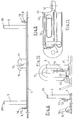
- Figures 1 to 3 show all the components of the line-up mechanism (3) according to the invention on an only indicated folder (1), which in particular can also be a ring binder.
- a base plate (4) is fastened, in particular riveted, to the inside (2) of the folder (1), which has, in the usual way, stationary alignment pins (5).
- the base plate (4) is formed from an embossed sheet, which in the usual way has a peripheral edge area and a raised base surface so that the riveting pins (5) can be riveted from the back of the base surface.
- a bracket (7) extends parallel to the base plate (4) and is rotatably mounted on the base plate (4) in the pivot bearing (8).
- This bracket bar (7) carries the movable bracket (6), which are accordingly also pivotable about the pivot bearing (8).
- the movable brackets (6) have concave formations (27) at their free ends and the stationary alignment pins (5) have convex formations (26) at their free ends, which engage in the closed position of the alignment mechanism (3).
- the mounting of the bracket (7) on the base plate (4) is effected by angled sheet metal sections (16) of the base plate (4), which are created by punching (20) the base plate (4) and angling.
- angled sheet metal sections (16) there are bores (17) into which protruding lugs (15) engage on the narrow end edges (14) of the bracket bar (7).
- the projections (15) are designed as prismatic sheet metal sections, the diagonal dimensions of which correspond to the diameter of the bore (17).
- first tab (10) On the edge (9) of the ironing bar (7) facing the alignment pins (5) there is an upright first tab (10) in the central area thereof, which has a pivot bearing (18) for a latch (12), which is therefore parallel to Can move tab level.
- first tab (10) can be seen in detail in FIG.
- this second tab (11) On the base plate (4) there is a second tab (11) which, as shown in FIGS. 8 and 9, is angled out of the plane of the base plate (4) by being punched out. In the closed position of the line-up mechanism (3), this second tab (11) extends parallel to the first tab (10) of the bracket bar (7), but while maintaining an intermediate space between the two tabs (10, 11). In this space, the bolt (12) is rotatably mounted, which cooperates with a stop (13), as shown in detail in Figures 2 and 7.
- the stop (13) is produced by punching (19) the tab (11) and by angling a nose forming the stop (13).
- the pivot bearing (18) of the bolt (12) is arranged above the stop (13).
- This arrangement is located on the other side in the direction of the stationary alignment pins (5) from an imaginary plane (25), which is symbolically represented in FIG. 1 and between the pivot bearing (8) of the bracket strip (7) and the ends (26, 27) the alignment pins (5) or the bracket (6) in the closed position of the alignment mechanism (3).
- This arrangement of the bolt (12) and Stop (13) beyond the plane (25) is achieved that the closed position of the line mechanism (3) is maintained without having to overcome any resilient bias of any parts.
- the folder according to the invention with the line mechanism (3) can therefore be locked very easily in the closed position by bringing the tabs (10, 11) into a position parallel to one another and pivoting the bolt (12).
- the invention is particularly suitable for using sheet groups (29) with protruding wire eyelets (30) on the line-up mechanism (3) without having to accept widening of the back.
- the tabs (10, 11) can be placed close to the line of alignment between the stationary alignment pins (5).
- FIG. 1 shows the arrangement of a group of sheets (29) by means of wire eyelets (30).
- FIG. 7 shows a side view of the latch (12) according to the invention.
- a recess (21) below the pivot bearing (18) of the bolt (12) which is formed by edges (22, 23) of the bolt (12) running at an acute angle to one another.
- the lower edge (23) of the recess (21) merges into an undercut step (24) in which the stop (13) (see FIG. 2) comes to rest in the closed position of the line-up mechanism (3).
- Both this undercut (24) and the geometry according to FIG. 1 ensure that the closed line-up mechanism (3) cannot be easily opened under external influence. Rather, opening is a pivoting of the bolt (12) according to the arrows in Figure 2 required to remove the recess (21) of the bolt (12) from the stop (13).
- the variant of the bolt (12) shown in FIG. 7a contains an actuating head (28) which can be clamped onto the web of the bolt (12), preferably made of plastic, which can have a cavity (29) in order to save weight and costs.
- This head (28) facilitates the actuation of the bolt (12) despite the reduction in the overall width of the line-up mechanism that can be achieved by the invention.
- FIGS. 10 and 11 show how one can support the edge of the individual leaf group (31) from below in order to secure a restoring force of the clamped leaf group (31) against the locking of the bolt (12) and stop (13 ) to create.
- two raised supports in the form of tongues (32) are provided on both sides of the locking mechanism (12, 13) on the top of the base plate (4), which act against the underside of the lowermost sheet edge.
- the base plate (4) receives a stamping (33) for each tongue (32), at the edge of which the tongue (32) is formed by bending a corresponding sheet metal section.
- the tongue (32) expediently lies at the end of a raised ledge (34) of the base plate (4), which serves on the one hand as a bead-like sheet metal reinforcement and also on the support of the sheet edge.
Landscapes
- Sheet Holders (AREA)
Applications Claiming Priority (4)
| Application Number | Priority Date | Filing Date | Title |
|---|---|---|---|
| DE29602131 | 1996-02-08 | ||
| DE29602131U | 1996-02-08 | ||
| DE29612892U | 1996-07-25 | ||
| DE29612892U DE29612892U1 (de) | 1996-02-08 | 1996-07-25 | Ordner mit einer Aufreihmechanik für gelochte Blätter |
Publications (2)
| Publication Number | Publication Date |
|---|---|
| EP0788892A2 true EP0788892A2 (fr) | 1997-08-13 |
| EP0788892A3 EP0788892A3 (fr) | 1998-05-27 |
Family
ID=26058625
Family Applications (1)
| Application Number | Title | Priority Date | Filing Date |
|---|---|---|---|
| EP97101866A Withdrawn EP0788892A3 (fr) | 1996-02-08 | 1997-02-06 | Classeur avec un mécanisme de reliure pour des feuilles perforées |
Country Status (1)
| Country | Link |
|---|---|
| EP (1) | EP0788892A3 (fr) |
Citations (2)
| Publication number | Priority date | Publication date | Assignee | Title |
|---|---|---|---|---|
| DE687634C (de) | 1937-07-29 | 1940-02-02 | Ferd Ashelm Komm Ges | Briefordner mit einem schwenkbaren Ruecklegerbuegelpaar |
| DE3610929C1 (de) | 1986-01-08 | 1987-04-02 | King Jim Co Ltd | Schwenkbare Haltevorrichtung fuer einen Ordner |
Family Cites Families (2)
| Publication number | Priority date | Publication date | Assignee | Title |
|---|---|---|---|---|
| DE420125C (de) * | 1924-10-31 | 1925-10-17 | Herm Herdegen Fa | Verschlussvorrichtung fuer die Aufreihnadeln von Briefordner-Mechaniken |
| DE704600C (de) * | 1939-10-15 | 1941-04-02 | Gruenewalds Registrator Co G M | Briefordnermechanik |
-
1997
- 1997-02-06 EP EP97101866A patent/EP0788892A3/fr not_active Withdrawn
Patent Citations (2)
| Publication number | Priority date | Publication date | Assignee | Title |
|---|---|---|---|---|
| DE687634C (de) | 1937-07-29 | 1940-02-02 | Ferd Ashelm Komm Ges | Briefordner mit einem schwenkbaren Ruecklegerbuegelpaar |
| DE3610929C1 (de) | 1986-01-08 | 1987-04-02 | King Jim Co Ltd | Schwenkbare Haltevorrichtung fuer einen Ordner |
Also Published As
| Publication number | Publication date |
|---|---|
| EP0788892A3 (fr) | 1998-05-27 |
Similar Documents
| Publication | Publication Date | Title |
|---|---|---|
| DE69311697T2 (de) | Verbesserungen an oder bezüglich der Ringschienenteile einer Ringbuchmechanik | |
| DE2729151C2 (de) | Sicherheitsgurtverschluß | |
| DE102006004113A1 (de) | Ringordnermechanik | |
| EP1367203B1 (fr) | Charnière | |
| DE8803353U1 (de) | Schnellhefter | |
| CH619124A5 (fr) | ||
| DE19602813A1 (de) | Einrichtung zur Befestigung einer Haltemechanik | |
| DE102004036779A1 (de) | Notizbuch | |
| DE2907718A1 (de) | Vorrichtung zum lochen | |
| EP0788892A2 (fr) | Classeur avec un mécanisme de reliure pour des feuilles perforées | |
| DE69607942T2 (de) | Ringordner | |
| DE69904196T2 (de) | Ordner | |
| DE2702042B2 (de) | Einhängeeinrichtung für Aktenordner | |
| DE2102385C3 (de) | Tastenschalter-Tableau-Mechanik | |
| DE29612892U1 (de) | Ordner mit einer Aufreihmechanik für gelochte Blätter | |
| EP0911180B1 (fr) | Mécanisme d'enfilage | |
| DE112006000697B4 (de) | Bindevorrichtung für Akten und Ordner | |
| DE69102576T2 (de) | Verriegelungsvorrichtung für Briefordner. | |
| DE3146393C2 (de) | Briefordnermechanik | |
| DE1436175C (de) | Ordner für Schriftgut | |
| EP0322506B1 (fr) | Système de classement par suspension | |
| DE19621619C2 (de) | Türschloß | |
| AT413969B (de) | Aktenordner | |
| DE2428324C3 (de) | Ringbuch für Hängeablage | |
| DE29713671U1 (de) | Einrichtung zum umblätterbaren Ablegen von flachen Gegenständen, insbesondere Compact-Discs |
Legal Events
| Date | Code | Title | Description |
|---|---|---|---|
| PUAI | Public reference made under article 153(3) epc to a published international application that has entered the european phase |
Free format text: ORIGINAL CODE: 0009012 |
|
| AK | Designated contracting states |
Kind code of ref document: A2 Designated state(s): AT DE ES FR GB IT SE |
|
| PUAL | Search report despatched |
Free format text: ORIGINAL CODE: 0009013 |
|
| AK | Designated contracting states |
Kind code of ref document: A3 Designated state(s): AT DE ES FR GB IT SE |
|
| STAA | Information on the status of an ep patent application or granted ep patent |
Free format text: STATUS: THE APPLICATION IS DEEMED TO BE WITHDRAWN |
|
| 18D | Application deemed to be withdrawn |
Effective date: 19981128 |