EP0788936A2 - Kraftschlüssige Befestigung einer Aufblasvorrichtung - Google Patents
Kraftschlüssige Befestigung einer Aufblasvorrichtung Download PDFInfo
- Publication number
- EP0788936A2 EP0788936A2 EP96306189A EP96306189A EP0788936A2 EP 0788936 A2 EP0788936 A2 EP 0788936A2 EP 96306189 A EP96306189 A EP 96306189A EP 96306189 A EP96306189 A EP 96306189A EP 0788936 A2 EP0788936 A2 EP 0788936A2
- Authority
- EP
- European Patent Office
- Prior art keywords
- inflator
- flange
- mount
- annular bracket
- base plate
- Prior art date
- Legal status (The legal status is an assumption and is not a legal conclusion. Google has not performed a legal analysis and makes no representation as to the accuracy of the status listed.)
- Withdrawn
Links
- 230000002093 peripheral effect Effects 0.000 claims abstract description 14
- 238000010276 construction Methods 0.000 claims description 2
- 238000000034 method Methods 0.000 description 4
- 238000002788 crimping Methods 0.000 description 3
- 239000000463 material Substances 0.000 description 3
- 238000004519 manufacturing process Methods 0.000 description 2
- 230000001960 triggered effect Effects 0.000 description 2
- 229910000639 Spring steel Inorganic materials 0.000 description 1
- 208000027418 Wounds and injury Diseases 0.000 description 1
- 230000006378 damage Effects 0.000 description 1
- 208000014674 injury Diseases 0.000 description 1
- 230000000452 restraining effect Effects 0.000 description 1
- 230000007704 transition Effects 0.000 description 1
Images


Classifications
-
- B—PERFORMING OPERATIONS; TRANSPORTING
- B60—VEHICLES IN GENERAL
- B60R—VEHICLES, VEHICLE FITTINGS, OR VEHICLE PARTS, NOT OTHERWISE PROVIDED FOR
- B60R21/00—Arrangements or fittings on vehicles for protecting or preventing injuries to occupants or pedestrians in case of accidents or other traffic risks
- B60R21/02—Occupant safety arrangements or fittings, e.g. crash pads
- B60R21/16—Inflatable occupant restraints or confinements designed to inflate upon impact or impending impact, e.g. air bags
- B60R21/20—Arrangements for storing inflatable members in their non-use or deflated condition; Arrangement or mounting of air bag modules or components
- B60R21/217—Inflation fluid source retainers, e.g. reaction canisters; Connection of bags, covers, diffusers or inflation fluid sources therewith or together
Definitions
- the present invention relates to an inflator mount for use with an airbag module. More particularly, the present invention relates to a press-on inflator mount that attaches to an inflator and is adapted to mount the inflator in a driver side airbag module.
- Providing a separate easily attachable inflator mount that can be pressed onto an inflator, mount the inflator within an airbag module, and prevent inflator rotation with respect to the inflator mount would be useful.
- Providing an inflator mount that is unitary with a module housing of an airbag module would also be desirable.
- Inflators are used in airbag modules that are in turn used in inflatable restraint systems. Inflatable restraint systems are employed in automobiles for protecting an occupant against injury by physically restraining the occupant's body when the automobile encounters a collision.
- the airbag module normally includes an inflator, a module housing and an airbag cushion.
- the module housing includes a base plate that supports the inflator and airbag cushion, and a housing sidewall that surrounds the folded airbag cushion.
- the inflator includes an inflator housing containing a gas generant material that, once triggered by a remote collision sensor, provides the inflation gas for inflating the airbag cushion.
- the inflator housing has a cylindrical sidewall forming a plurality of gas exhaust ports, and an integral peripheral bracket that extends radially outwardly from the sidewall below the gas exhaust ports.
- the base plate of the module housing has an inflator-receiving hole with a portion of the inflator extending therethrough.
- the airbag cushion has an open mouth formed by a collar that fits over the inflator with the collar positioned against the base plate so that the gas exhaust ports are located within the open mouth.
- the collar of the airbag cushion and the peripheral bracket of the inflator are secured to the base plate of the module housing, holding the airbag module together, and preventing the airbag cushion and inflator from becoming separated during inflation of the airbag cushion.
- an inflator mount in place of the peripheral bracket that is separate from, yet easily attachable to the inflator would save manufacturing time and reduce costs. Because the peripheral bracket is integral with the inflator housing on most existing inflators, the inflator housing is much more difficult and costly to fabricate. Using a stamping technique to manufacture the inflator, which is preferably from a cost standpoint, does not readily allow incorporating the peripheral bracket as an integral part of the inflator. Accordingly, providing an inflator housing that does not have an integral peripheral mounting bracket but has a separate, attachable, inflator mount that can be easily attached to the inflator prior to installing the inflator within the airbag module would be useful.
- a separate inflator mount should attach to and mount an inflator so that the inflator will not become unattached from the airbag module during inflation of the airbag cushion. Forces which tend to pull the airbag module apart are produced during inflation of the airbag cushion, and the inflator mount should secure the inflator to withstand these forces. As with all components used in automobiles, the inflator mount should also mount the inflator in a squeak and rattle-free manner. If the inflator mount could be unitary with the module housing it would reduce the number of separate parts comprising the airbag module and simplify assembly of the airbag module.
- U.S. Patent 5,275,431 provides an inflator and a separate retainer member or inflator mount that is secured to the inflator using a radial crimping or forming method.
- the '431 inflator has an inflator flange and the inflator mount has an annular wall surface or cylindrical sleeve encircling the inflator and the inflator flange.
- a crimped portion or flange clamp is formed in the sleeve using a radial crimping or forming method.
- the flange clamp clamps the inflator flange against the support ring securing the inflator mount to the inflator.
- the inflator mount on this inflator therefore, requires an additional assembly step, crimping the sleeve, after being placed on the inflator.
- the inflator mount should lock onto the inflator, mount the inflator within an airbag module, and prevent inflator rotation with respect to the inflator mount.
- the inflator mount should also secure the inflator to the airbag module to withstand the expansive forces during inflation of the airbag, and provide shake and rattle-free mounting. It would also be useful to provide a unitary module housing and inflator mount.
- An object, therefore, of the present invention is to provide a separate inflator mount that is easily attached and secured to an inflator without requiring a further assembly step.
- Another object of the present invention is to provide a separate inflator mount that secures an inflator to an airbag module and prevents rotation of the inflator with respect to the mount.
- An additional object of the present invention is to provide a separate inflator mount that easily attaches to an inflator and secures the inflator within an airbag module to withstand the excessive forces created during inflation of the airbag cushion.
- a further object of the present invention is to provide a separate inflator mount that provides shake and rattle-free mounting of an inflator.
- Yet another object of the present invention is to provide an inflator mount that is unitary with a module housing of an airbag module.
- an inflator mount for attachment to an inflator having a cylindrical sidewall and a peripheral inflator flange radially extending from the sidewall, and for mounting the inflator within an airbag module.
- the inflator mount includes a generally flat annular bracket having an inside edge defining an opening that accommodates passage of the radially extending peripheral inflator flange.
- An inflator flange grip extends downwardly and inwardly from the inside edge of the annular bracket.
- the inflator flange grip slidingly receives and grippingly engages the inflator flange and embraces the underside thereof to secure the inflator mount to the inflator and adapt the inflator and inflator mount for mounting in an airbag module by means of the annular bracket.
- the inflator flange grip comprises a cylindrical sleeve and a lower support ring.
- the sleeve extends downwardly from the annular bracket and frictionally and grippingly engages the outer periphery of the inflator flange, and the lower support ring extends inwardly from the cylindrical sleeve and embraces at least a portion of the underside of the flange.
- the inflator flange grip further includes a flange clamp adapted to extend over at least a portion of the inflator flange and clamp the inflator flange against the support ring.
- the flange clamp comprises a plurality of spaced-apart, resilient, snap tabs extending inwardly from the sleeve. The tabs are adapted to resiliently bend outward to slide over the flange, and once over the flange, resiliently bend inward to clamp the flange against the support ring.
- the flange clamp comprises a plurality of spaced-apart dimples extending inwardly from the sleeve and which are received over the inflator flange.
- the cylindrical sleeve and support ring comprise at least two discontinuous segments. Each sleeve segment has a continuous radial rib extending inwardly to comprise the flange clamp.
- a unitary module housing and inflator mount includes a housing base plate having a unitary annular bracket with an inner edge defining an opening accommodating passage of the inflator flange.
- a housing sidewall extends upwardly from an outer edge of the housing base plate and defines an open top of the module housing.
- the unitary module housing and inflator further includes an inflator flange grip extending downwardly from the inner edge of the annular bracket. The inflator flange grip slidingly receives and grippingly engages the inflator flange and embraces the underside thereof to secure the unitary module housing and inflator mount to the inflator for mounting in an airbag module.
- the present invention therefore, provides an inflator mount that can be easily pressed onto an inflator and secured thereto without having to crimp the inflator mount or perform any further assembly steps.
- the present invention also provides the inflator mount for mounting in or unitary with a module housing.
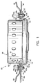
- the present invention is directed to an inflator mount 10 for attachment to an inflator 80 having a cylindrical sidewall 82 and a peripheral inflator flange 84 radially extending from the sidewall 82 .
- the inflator mount is adapted to mount the inflator 80 within an airbag module 85 .
- the inflator mount 10 includes a continuous, generally flat, annular bracket 12 having an inside edge 13 defining an opening 14 accommodating passage of the radially extending peripheral inflator flange 84 .
- An inflator flange grip 16 extends downwardly and inwardly from the inside edge 13 of the annular bracket 12 .
- the flange grip 16 slidingly receives and grippingly engages the inflator flange 84 and embraces the underside thereof to secure the inflator mount 10 to the inflator 80 and adapt the inflator and inflator mount 10 for mounting in an airbag module 85 by means of the annular bracket 12 .
- the flange grip 16 comprises a continuous cylindrical sleeve 18 and a continuous lower support ring 20 , although both could be provided in discontinuous segments.
- the sleeve 18 extends downwardly from the annular bracket 12 and frictionally and grippingly engages the outer periphery of the inflator flange 84 .
- the lower support ring 20 extends inwardly from the cylindrical sleeve 18 and conforms to and embraces at least a portion of the underside of the flange 84.
- the inflator mount 10 is made of spring steel or another suitable material and is a one-piece stamped member. During assembly, the inflator mount 10 is pressed onto the inflator 80 .
- the cylindrical sleeve 18 of the inflator mount 10 is of slightly smaller diameter than the inflator flange 84 and as the sleeve 18 slides over the flange 84 it resiliently deforms outwardly to accept the flange 84 .
- the resilient deformation causes the sleeve 18 to radially clamp and frictionally engage the flange 84 to secure the inflator mount 10 to the inflator 80 and prevent inflator rotation with respect to the inflator mount 10 .
- the inflator mount 10 is ready to be secured in an airbag module 85 .
- FIG. 1 also shows the inflator mount 10 and inflator 80 secured in a driver side airbag module 85 .
- the airbag module 85 includes an airbag cushion 88, an airbag retainer 89 and a module housing 86 having a base plate 87 .
- the cylindrical sidewall 82 of the inflator 80 includes a plurality of gas exhaust ports 81 and contains a gas generant material that, once triggered by a remote collision sensor (not shown), provides the inflation gas for inflating the airbag cushion 88 .
- the annular bracket 12 of the inflator mount 10 is positioned against the base plate 87 so that a portion of the sidewall 82 containing the gas exhaust ports 81 extends through an inflator receiving hole 90 in the base plate 87 .
- the airbag cushion 88 has an open mouth 91 formed by a collar 92 that fits over the inflator 80 with the collar 92 positioned against the base plate 87 so that the gas exhaust ports 81 are located within the open mouth 91 .
- the airbag retainer 89 is positioned over the collar 92 of the airbag cushion 88 and the retainer 89 , collar 92 and annular bracket 12 are secured to the base plate 87 with fasteners 93a,93b .
- the fasteners 93a,93b pass through, respectively, receiving holes 94a,94b in the retainer 89 , receiving holes 95a,95b in the collar 92 , receiving holes 96a,96b in the base plate 87 and receiving holes 22,23 in the annular bracket 12, and are secured with nuts 98,99 or the like.
- inflation forces tend to push the inflator 80 downward and the support ring 20 holds the inflator 80 within the airbag module 85 .
- an inflator mount 110 similar to the inflator mount 10 of FIG. 1 is shown unitary with a module housing 112 according to the present invention.
- the module housing 112 has a base plate 114 which includes as a unitary construction an annular bracket 115 of the inflator mount 110 .
- the dotted line is provided to indicate a transition between the base plate 114 and the annular bracket 115 of module housing 112 , although it will be appreciated they are a unitary one-piece structure.
- An inner edge 116 of annular bracket 115 defines an opening 118 accommodating passage of the inflator flange, and a housing sidewall 120 extends upwardly from an outer edge 119 of the base plate 114 .
- the housing sidewall 120 ends in a curled lip 122 defining an open top 124 of the module housing 112 .
- the unitary module housing 112 and inflator mount 110 further includes an inflator flange grip 126 extending downwardly and inwardly from the inner edge 116 of the annular bracket 115 .
- the inflator flange grip 126 comprises a continuous cylindrical sleeve 128 and a lower support ring 130 .
- the base plate 114 and housing sidewall 120 are generally rectangular, but other shapes are suitable.
- the annular bracket 115 defines fastener receiving holes 132 for mounting an airbag cushion (not shown but similar to the airbag cushion 88 of FIG. 1 ).
- the housing sidewall 120 is adapted to surround the airbag cushion, which is folded within the module housing 112 prior to inflation.
- the curled lip 122 of the housing sidewall 120 is normally adapted to catch the edges of an airbag module cover (not shown) to close the open top of the module housing 112 .
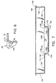
- the inflator mount 30 has an annular bracket 12 , having an inner edge 13, opening 14 and fastener receiving holes 22,23,24,25, and an inflator flange grip 16 comprising a cylindrical sleeve 18 and a support ring 20 .
- the inflator mount 30 includes a flange clamp 32 adapted to extend over at least a portion of the inflator flange 84 and clamp the inflator flange 84 against the support ring 20 .
- the flange clamp 32 comprises four spaced-apart, resilient, snap tabs 34a,34b,34c (the fourth snap tab is not shown, but is similar to and positioned opposite snap tab 34c ) that extend inwardly from the cylindrical sleeve 18 and are resiliently deformable.
- the tabs 34a,34b,34c resiliently bend to slide over the inflator flange 84 as the flange 84 is inserted through opening 14 and, once over the flange 84 , resilient bend back to extend inwardly over the flange 84 to clamp the flange 84 against the support ring 20 .
- an inflator mount 134 similar to the inflator mount 30 of FIGS. 4 - 6 is shown unitary with a module housing 136 according to the present invention.
- the unitary module housing 136 and inflator mount 134 includes a base plate 138 having a unitary annular bracket 139 with an inner edge 140 defining an opening 142 accommodating passage of an inflator flange.
- a housing sidewall 144 extends upwardly from an outer edge 145 of the base plate 138 and ends in a curled lip 146 defining an open top 148 of the module housing 136 .
- the unitary module housing 136 and inflator mount 134 further includes an inflator flange grip 150 extending downwardly and inwardly from the inner edge 140 of the annular bracket 139 .
- the inflator flange grip 150 comprises a continuous cylindrical sleeve 152 and a lower support ring 154 .
- the inflator mount 134 includes a flange clamp 156 comprising four spaced-apart, resilient, snap tabs 158a,158b,158c that extend inwardly from the cylindrical sleeve 152 and are resiliently deformable (the fourth snap tab is not shown but is similar to and opposite from snap tab 158b) .
- Fastener receiving holes 159 for mounting an airbag cushion are provided in the annular bracket 139 .
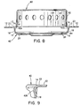
- the inflator mount 40 has an annular bracket 12 and an inflator flange grip 16 comprising a cylindrical sleeve 18 and a support ring 20 .
- the inflator mount 40 includes a flange clamp 41 that comprises four spaced-apart dimples 42a,42b (the two other dimples are not shown but are similar to dimples 42a,42b ) extending inwardly from the cylindrical sleeve 18 .
- the sleeve 18 elastically deforms to allow the inflator mount 40 to be pressed onto the inflator 80 , with the dimples 42a,42b sliding over the inflator flange 84 . Once past the flange 84 , the dimples 42a,42b extend over the flange 84 to clamp the flange 84 against the support ring 20 and further secure the inflator mount 40 to the inflator 80 .
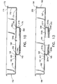
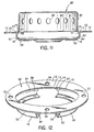
- an inflator mount 160 similar to the inflator mount 40 of FIGS. 8 and 9 is shown unitary with a module housing 162 according to the present invention.
- the unitary module housing 162 and inflator mount 160 includes a base plate 164 having a unitary annular bracket 165 with an inner edge 166 defining an opening 168 accommodating passage of an inflator flange.
- a housing sidewall 170 extends upwardly from an outer edge 171 of the base plate 164 and ends in a curled lip 172 defining an open top 174 of the module housing 162 .
- the unitary module housing 162 and inflator mount 160 haves an inflator flange grip 176 extending downwardly and inwardly from the inner edge 166 of the annular bracket 165 .
- the inflator flange grip 176 comprises a continuous cylindrical sleeve 178 and a lower support ring 180 .
- the inflator mount 160 includes a flange clamp 182 comprising four spaced-apart dimples 184a,184b,184c that extend inwardly from the cylindrical sleeve 178 (the fourth dimple is not shown but is similar to and opposite from dimple 184b ).
- Fastener receiving holes 185 for mounting an airbag cushion are provided in the annular bracket 165 .
- the inflator mount 50 has an annular bracket 12 and an inflator flange grip 16 comprising a cylindrical sleeve 52,53 a support ring 54,55 and a flange clamp 51 .
- the cylindrical sleeve 52,53 and support ring 54,55 each comprise two discontinuous segments and each sleeve segment 52,53 has a continuous radial rib 56,57, the ribs 56,57 comprise the flange clamp 51 .
- the discontinuous sleeve 52,53 and support ring 54,55 deform outwardly to allow the ribs 56,57 to slide over the inflator flange 84 to be seated over and adjacent the flange 84 and clamp the flange 84 against the support ring 54,55, further securing the inflator mount 50 to the inflator 80 .
- an inflator mount 186 similar to the inflator mount 50 of FIGS. 8 and 9 is shown unitary with a module housing 188 according to the present invention.
- the unitary module housing 188 and inflator mount 186 include a base plate 190 having a unitary annular bracket 191 with an inner edge 192 defining an opening 194 accommodating passage of an inflator flange.
- a housing sidewall 196 extends upwardly from an outer edge 197 of the base plate 190 and ends in a curled lip 198 defining an open top 200 of the module housing 188 .
- the unitary module housing 188 and inflator mount 186 has an inflator flange grip 202 extending downwardly and inwardly from the inner edge 192 of the annular bracket 191 .
- the inflator flange grip 202 comprises two discontinuous segments of a cylindrical sleeve 204a,204b and a lower support ring 206a,206b .
- the inflator mount 186 includes a flange clamp 208 comprising a radial rib 210a,210b on each segment of the sleeve 204a,204b .
- Fastener receiving holes 211 for mounting an airbag cushion are provided in the annular bracket 191 .
- the inflator mounts adapt an inflator for mounting within an airbag module in a manner similar to that shown in FIG. 1 with respect to inflator mount 10 .
- the present invention therefore, provides a simple, reliable and low cost method of attaching a separate inflator mount to a driver side airbag inflator that allows greater flexibility in the design of the inflator mount and inflator.
- the inflator mount secures to the inflator, mounts the inflator within an airbag module assembly, and prevents inflator rotation with respect to the inflator mount.
- the inflator mount also secures the inflator to the airbag module assembly to withstand the expansive forces during inflation of the airbag, and provides shake and rattle-free mounting.
- the present invention also provides an inflator mount with a module housing that reduces the number of separate parts comprising the airbag module, and simplify assembly of the airbag module.
Landscapes
- Engineering & Computer Science (AREA)
- Mechanical Engineering (AREA)
- Air Bags (AREA)
Applications Claiming Priority (4)
| Application Number | Priority Date | Filing Date | Title |
|---|---|---|---|
| US566886 | 1975-04-10 | ||
| US52297895A | 1995-09-01 | 1995-09-01 | |
| US522978 | 1995-09-01 | ||
| US08/566,886 US5547213A (en) | 1995-09-01 | 1995-12-04 | Press-on inflator mount |
Publications (2)
| Publication Number | Publication Date |
|---|---|
| EP0788936A2 true EP0788936A2 (de) | 1997-08-13 |
| EP0788936A3 EP0788936A3 (de) | 1997-10-08 |
Family
ID=27060997
Family Applications (1)
| Application Number | Title | Priority Date | Filing Date |
|---|---|---|---|
| EP96306189A Withdrawn EP0788936A3 (de) | 1995-09-01 | 1996-08-27 | Kraftschlüssige Befestigung einer Aufblasvorrichtung |
Country Status (1)
| Country | Link |
|---|---|
| EP (1) | EP0788936A3 (de) |
Family Cites Families (4)
| Publication number | Priority date | Publication date | Assignee | Title |
|---|---|---|---|---|
| US5141247A (en) * | 1990-12-18 | 1992-08-25 | Trw Inc. | Air bag inflator assembly |
| US5275431A (en) * | 1991-09-18 | 1994-01-04 | Trw Inc. | Air bag inflator assembly |
| US5433472A (en) * | 1994-03-31 | 1995-07-18 | Morton International, Inc. | Quick-locking device for retention of an inflator in a passenger-side canister |
| US5498029A (en) * | 1995-01-19 | 1996-03-12 | Morton International, Inc. | Toothed inflator adapter for an airbag assembly |
-
1996
- 1996-08-27 EP EP96306189A patent/EP0788936A3/de not_active Withdrawn
Also Published As
| Publication number | Publication date |
|---|---|
| EP0788936A3 (de) | 1997-10-08 |
Similar Documents
| Publication | Publication Date | Title |
|---|---|---|
| US5547213A (en) | Press-on inflator mount | |
| US5503426A (en) | Method of attaching a mounting bracket to an airbag inflator | |
| US5947509A (en) | Airbag inflator with snap-on mounting attachment | |
| US6029992A (en) | Air bag module and steering wheel assembly | |
| US20020084630A1 (en) | Retaining device | |
| US5611563A (en) | Airbag inflator attachment with snap-in sleeve | |
| US5234227A (en) | Mounting for air bag assembly | |
| US6196573B1 (en) | Mounting mechanism for inflatable restraint system | |
| JPH082362A (ja) | エアバッグモジュール | |
| US5275431A (en) | Air bag inflator assembly | |
| EP0733516A1 (de) | Luftsack-Befestigungsring, ohne Nieten, mit Laschen, die den Ring nach Rotation fixieren | |
| JP3037229U (ja) | エアバッグモジュール | |
| JP3044721U (ja) | エアバッグインフレータ保持用タブ | |
| EP0631908B1 (de) | Antiklapperstruktur zur Befestigung einer flanschlosen Aufblasvorrichtung in einem Luftsackrückhaltesystem | |
| US5520411A (en) | Cover mounting for an airbag assembly | |
| US5577763A (en) | Air bag mounting structure and method | |
| JP3031591U (ja) | エアバッグモジュール | |
| US5259641A (en) | Air bag attachment device | |
| EP0551732A1 (de) | Platten zur Befestigung eines Gaskissens auf einem Lenkrad | |
| JP3034963U (ja) | エアバッグモジュール組体用の無フランジ膨張器 | |
| US6799774B2 (en) | Airbag module | |
| US6325407B1 (en) | Airbag module cover attachment | |
| EP0788936A2 (de) | Kraftschlüssige Befestigung einer Aufblasvorrichtung | |
| US7556281B2 (en) | Stamped airbag retention members and method of airbag assembly | |
| US5496057A (en) | Air bag module cover retainer |
Legal Events
| Date | Code | Title | Description |
|---|---|---|---|
| PUAI | Public reference made under article 153(3) epc to a published international application that has entered the european phase |
Free format text: ORIGINAL CODE: 0009012 |
|
| AK | Designated contracting states |
Kind code of ref document: A2 Designated state(s): DE FR GB IT |
|
| PUAL | Search report despatched |
Free format text: ORIGINAL CODE: 0009013 |
|
| AK | Designated contracting states |
Kind code of ref document: A3 Designated state(s): DE FR GB IT |
|
| 17P | Request for examination filed |
Effective date: 19971031 |
|
| 17Q | First examination report despatched |
Effective date: 19990729 |
|
| STAA | Information on the status of an ep patent application or granted ep patent |
Free format text: STATUS: THE APPLICATION IS DEEMED TO BE WITHDRAWN |
|
| 18D | Application deemed to be withdrawn |
Effective date: 19991209 |