EP0788937A2 - Ligne de rupture de couvercle de sac gonflable - Google Patents
Ligne de rupture de couvercle de sac gonflable Download PDFInfo
- Publication number
- EP0788937A2 EP0788937A2 EP96306445A EP96306445A EP0788937A2 EP 0788937 A2 EP0788937 A2 EP 0788937A2 EP 96306445 A EP96306445 A EP 96306445A EP 96306445 A EP96306445 A EP 96306445A EP 0788937 A2 EP0788937 A2 EP 0788937A2
- Authority
- EP
- European Patent Office
- Prior art keywords
- tearseam
- panel
- cover
- primary
- tearseams
- Prior art date
- Legal status (The legal status is an assumption and is not a legal conclusion. Google has not performed a legal analysis and makes no representation as to the accuracy of the status listed.)
- Withdrawn
Links
- 230000007704 transition Effects 0.000 claims abstract description 12
- 230000009172 bursting Effects 0.000 abstract description 4
- 239000000463 material Substances 0.000 description 4
- 230000015572 biosynthetic process Effects 0.000 description 2
- 238000000034 method Methods 0.000 description 2
- 238000010276 construction Methods 0.000 description 1
- 238000010348 incorporation Methods 0.000 description 1
- 238000009434 installation Methods 0.000 description 1
- 239000002245 particle Substances 0.000 description 1
- 230000000717 retained effect Effects 0.000 description 1
- 238000000926 separation method Methods 0.000 description 1
Images

Classifications
-
- B—PERFORMING OPERATIONS; TRANSPORTING
- B60—VEHICLES IN GENERAL
- B60R—VEHICLES, VEHICLE FITTINGS, OR VEHICLE PARTS, NOT OTHERWISE PROVIDED FOR
- B60R21/00—Arrangements or fittings on vehicles for protecting or preventing injuries to occupants or pedestrians in case of accidents or other traffic risks
- B60R21/02—Occupant safety arrangements or fittings, e.g. crash pads
- B60R21/16—Inflatable occupant restraints or confinements designed to inflate upon impact or impending impact, e.g. air bags
- B60R21/20—Arrangements for storing inflatable members in their non-use or deflated condition; Arrangement or mounting of air bag modules or components
- B60R21/215—Arrangements for storing inflatable members in their non-use or deflated condition; Arrangement or mounting of air bag modules or components characterised by the covers for the inflatable member
- B60R21/2165—Arrangements for storing inflatable members in their non-use or deflated condition; Arrangement or mounting of air bag modules or components characterised by the covers for the inflatable member characterised by a tear line for defining a deployment opening
Definitions
- This invention relates to the field of automotive airbags. More particularly, it relates to an airbag cover having a novel tearseam construction.
- the conventional automotive airbag installation customarily includes a reaction canister which encloses a folded airbag, a source of pressurizing gas which inflates the airbag upon occurrence of a crash of sufficient magnitude, and a rupturable cover which closes the mouth of the reaction canister.
- the cover is conventionally formed and configured as a part of the vehicle's interior aesthetics.
- a driver's side airbag module is normally installed within the confines of the steering wheel.
- the passenger side airbag is conventionally mounted within the dashboard facing the passenger.
- the covers are normally designed to split open under the influence of the expanding airbag. This is achieved by lines of weakness in the airbag cover, conventionally termed "tearseams".
- the tearseams are configured such that, when bursting, they form one or more hinged doors which release the airbag into the vehicle interior.
- Several methods may be employed to form the rupturable tearseams.
- One of the simplest would be a series of perforations. However, this would probably not be aesthetically acceptable in a luxury or higher quality vehicle.
- a more common method is to form the tearseam as a groove along the hidden surface of the cover material, thereby thinning the cover material to an acceptable burst strength.
- one difficulty with this is that the initial tearseam may be visible from the front of the cover which is normally made of an injected molded material. This may be aesthetically undesirable.
- the invention comprises an airbag cover of the type having a main body with a front, normally exposed, surface.
- the cover includes an integral locking member which extends away from the cover main body to retain it in position on an airbag housing.
- the primary tearseam is defined by the locking member.
- a transition opening extends through the locking member at each end of the primary tearseam.
- Each of the transition openings communicates with a secondary tearseam in the main body of the airbag cover.
- the primary tearseam ruptures first, followed thereafter by the rupture of the secondary tearseams, thereby defining an airbag release door.
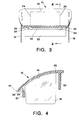
- FIGS. 1 and 2 there is illustrated an airbag module cover having a main body panel 10 with a front surface 12 and a rear surface 14 .
- Panel 10 is styled to fit within an automotive dashboard.
- the cover is an integrally molded unit which carries at each end left 16 and right 18 side flaps. The side flaps, however, do not form a part of the invention and need not be further described.
- Also molded integrally with the panel 10 is a rear locking member 20 and a front locking member 22 . (The terms “front,” “rear,” “top,” “bottom,” “left,” and “right” are all relative to drawing figures.
- the locking members 20, 22 are designed to be hidden from sight by extending into the reaction canister where they are retained by suitable locking means (not shown).
- suitable locking means not shown.
- the panel 10 As the panel 10 is designed to be incorporated into, and form a portion of, the vehicle dashboard, it is preferable that its front surface be visually uniform without disclosing the existence of the tearseams. However, it is also desired that the panel 10 be rupturable along tearlines 24, 26 to form an airbag release door extending from the front edge 40 of the panel 10 and pivotable along a hinge line 28.
- a primary tearseam 30 is formed in the front locking member 22 near its juncture with the rear surface 14 of the main body 10 and extending parallel thereto.
- the tearseam 30 is in the form of a semi-cylindrical groove.
- Any suitable means may be employed for the tearseam including grooves of different shape, incorporation of a weaker material, or even a series of perforations, the primary objective being to provide a tearseam which will burst under the force of an expanding airbag before the tearseams in the panel 10 to be described.
- the primary tearseam 30 extends horizontally along the surface of the locking member 22 and its ends terminate at left 32 and right 34 transition openings which are essentially semi-circular and each of which extends completely through the front locking member 22 .
- the transition openings need not be semi-circular and may or may not extend completely through the locking member. They need only to allow the tear to transition.
- left 36 and right 38 door-forming grooves which constitute secondary tearseams colinear with tearlines 24, 26 .
- these grooves are essentially V-shaped and extend from the front edge 40 of the panel 10 to the ends of the proposed hinge line 28 .
- the cross-sectional shape of the grooves 36, 38 is not important. However, they are designed to provide a tearseam which is slightly stronger than the primary tearseam 30 in the front locking member 22 . It is also desirable that they are not visible through the front surface of the panel 10 .
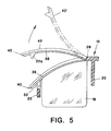
- Operation of the cover of this invention may be best understood by reference to FIG. 5 .
- the airbag within the reaction canister begins to expand, it applies an upward force against the panel 10 .
- the primary tearseam 30 in the front locking member 22 begins to rupture along its length until it reaches the left and right transition openings 32, 34 . In so rupturing, it releases a segment 22a of the front locking member 22 which remains attached to the panel 10 .
- the front edge 40 of the panel 10 between the transition openings 32, 34 begins to rise and, upon final separation of the primary tearseam 30 , the expanding force is transferred to the secondary tearseams defined by left door-forming groove 36 and right door-forming groove 38 .
Landscapes
- Engineering & Computer Science (AREA)
- Mechanical Engineering (AREA)
- Air Bags (AREA)
Applications Claiming Priority (2)
| Application Number | Priority Date | Filing Date | Title |
|---|---|---|---|
| US527492 | 1995-09-13 | ||
| US08/527,492 US5560647A (en) | 1995-09-13 | 1995-09-13 | Airbag cover tearseam transition |
Publications (2)
| Publication Number | Publication Date |
|---|---|
| EP0788937A2 true EP0788937A2 (fr) | 1997-08-13 |
| EP0788937A3 EP0788937A3 (fr) | 1998-07-29 |
Family
ID=24101676
Family Applications (1)
| Application Number | Title | Priority Date | Filing Date |
|---|---|---|---|
| EP96306445A Withdrawn EP0788937A3 (fr) | 1995-09-13 | 1996-09-05 | Ligne de rupture de couvercle de sac gonflable |
Country Status (3)
| Country | Link |
|---|---|
| US (1) | US5560647A (fr) |
| EP (1) | EP0788937A3 (fr) |
| JP (1) | JP3035685U (fr) |
Cited By (2)
| Publication number | Priority date | Publication date | Assignee | Title |
|---|---|---|---|---|
| DE102007007338B4 (de) * | 2006-02-14 | 2010-11-18 | Takata Corp. | Airbagmodul für die Verwendung in Fahrzeugen |
| CN105644488A (zh) * | 2014-12-02 | 2016-06-08 | 利萨·德雷克塞迈尔有限责任公司 | 安全气囊装饰弱化部的补偿齿孔 |
Families Citing this family (2)
| Publication number | Priority date | Publication date | Assignee | Title |
|---|---|---|---|---|
| US20070182131A1 (en) * | 2003-09-03 | 2007-08-09 | Michael Helbig | Housing for an airbag device |
| US20050082797A1 (en) * | 2003-10-16 | 2005-04-21 | Richard Welford | Expanding net integral with an inflatable airbag curtain |
Family Cites Families (5)
| Publication number | Priority date | Publication date | Assignee | Title |
|---|---|---|---|---|
| US5002307A (en) * | 1989-07-13 | 1991-03-26 | Sheller-Globe Corporation | Vehicle air bag safety system |
| JP2526171B2 (ja) * | 1990-09-28 | 1996-08-21 | 池田物産株式会社 | エアバッグ装置 |
| CA2056206C (fr) * | 1990-11-29 | 1996-02-06 | Asahi Kasei Kogyo Kabushiki Kaisha | Couvercle permettant le logement d'un airbag dans un systeme d'airbag |
| US5335935A (en) * | 1992-08-31 | 1994-08-09 | Plastic Mold Technology Incorporated | Air bag cover/molded article with integral cover layer of leather |
| GB2279302B (en) * | 1993-06-21 | 1996-06-12 | Autoliv Dev | Improvements in or relating to a cover for an air-bag |
-
1995
- 1995-09-13 US US08/527,492 patent/US5560647A/en not_active Expired - Lifetime
-
1996
- 1996-09-05 EP EP96306445A patent/EP0788937A3/fr not_active Withdrawn
- 1996-09-12 JP JP1996009250U patent/JP3035685U/ja not_active Expired - Lifetime
Cited By (3)
| Publication number | Priority date | Publication date | Assignee | Title |
|---|---|---|---|---|
| DE102007007338B4 (de) * | 2006-02-14 | 2010-11-18 | Takata Corp. | Airbagmodul für die Verwendung in Fahrzeugen |
| CN105644488A (zh) * | 2014-12-02 | 2016-06-08 | 利萨·德雷克塞迈尔有限责任公司 | 安全气囊装饰弱化部的补偿齿孔 |
| CN105644488B (zh) * | 2014-12-02 | 2019-04-23 | 利萨·德雷克塞迈尔有限责任公司 | 安全气囊装饰弱化部的补偿齿孔 |
Also Published As
| Publication number | Publication date |
|---|---|
| JP3035685U (ja) | 1997-03-28 |
| EP0788937A3 (fr) | 1998-07-29 |
| US5560647A (en) | 1996-10-01 |
Similar Documents
| Publication | Publication Date | Title |
|---|---|---|
| US6076851A (en) | Airbag surround for seamless instrument panel | |
| US5447327A (en) | Arrangement for providing an air bag deployment opening | |
| US5564733A (en) | Instrument panel having an integrated, swing-open air-bag cover | |
| US5728342A (en) | Method of making an invisible instrument panel or dashboard airbag cover door | |
| EP0629527B1 (fr) | Fermeture pour sac d'air | |
| US6536801B2 (en) | Gas bag module | |
| KR19990045155A (ko) | 에어백 커버 | |
| US20020014764A1 (en) | Decorative covering for air bag covers | |
| US5676394A (en) | Seat trim deployment cover for side airbag module | |
| JP3040711U (ja) | 閉鎖具 | |
| US6655711B1 (en) | Air bag cover assembly | |
| EP0710591B1 (fr) | Porte sans jointure pour module de coussin d'air | |
| EP1800971A1 (fr) | Tableau de bord avec air-bag pour passager | |
| JP2003137054A (ja) | エアバッグドアのインサート部材 | |
| EP0770522A1 (fr) | Dispositif pour faciliter l'ouverture d'un couvercle intégral de déploiement dans un panneau de recouvrement d'un système à sac gonflable | |
| EP1157903A2 (fr) | Module de coussin gonflable | |
| US5560647A (en) | Airbag cover tearseam transition | |
| JPH0781512A (ja) | エアバッグ展開用開口のための閉鎖要素 | |
| US5641178A (en) | Air bag device | |
| EP0709258A1 (fr) | Elément de retenue pour couvercle de coussin d'air | |
| EP2006167A2 (fr) | Structure de couvercle d'airbag | |
| US5755460A (en) | Instrument panel seamless air bag cover | |
| US6076849A (en) | Motor vehicle dashboard assembly | |
| EP1923275A2 (fr) | Module de coussin gonflable pour roues de direction de véhicule automobile | |
| JPH1159306A (ja) | 助手席用エアバッグ装置 |
Legal Events
| Date | Code | Title | Description |
|---|---|---|---|
| PUAI | Public reference made under article 153(3) epc to a published international application that has entered the european phase |
Free format text: ORIGINAL CODE: 0009012 |
|
| AK | Designated contracting states |
Kind code of ref document: A2 Designated state(s): DE FR GB IT |
|
| PUAL | Search report despatched |
Free format text: ORIGINAL CODE: 0009013 |
|
| AK | Designated contracting states |
Kind code of ref document: A3 Designated state(s): DE FR GB IT |
|
| 17P | Request for examination filed |
Effective date: 19980820 |
|
| 17Q | First examination report despatched |
Effective date: 19991122 |
|
| STAA | Information on the status of an ep patent application or granted ep patent |
Free format text: STATUS: THE APPLICATION IS DEEMED TO BE WITHDRAWN |
|
| 18D | Application deemed to be withdrawn |
Effective date: 20000404 |