EP0788966B1 - Vorrichtung zum Spannen und Abfedern des Leitrades von Kettenfahrzeugen - Google Patents
Vorrichtung zum Spannen und Abfedern des Leitrades von Kettenfahrzeugen Download PDFInfo
- Publication number
- EP0788966B1 EP0788966B1 EP96114922A EP96114922A EP0788966B1 EP 0788966 B1 EP0788966 B1 EP 0788966B1 EP 96114922 A EP96114922 A EP 96114922A EP 96114922 A EP96114922 A EP 96114922A EP 0788966 B1 EP0788966 B1 EP 0788966B1
- Authority
- EP
- European Patent Office
- Prior art keywords
- clamping plate
- spring
- unit
- spring unit
- chamber
- Prior art date
- Legal status (The legal status is an assumption and is not a legal conclusion. Google has not performed a legal analysis and makes no representation as to the accuracy of the status listed.)
- Expired - Lifetime
Links
- 238000010521 absorption reaction Methods 0.000 title claims 2
- 239000004519 grease Substances 0.000 claims abstract description 5
- 238000007789 sealing Methods 0.000 claims description 8
- 230000035939 shock Effects 0.000 claims description 2
- 230000001681 protective effect Effects 0.000 description 24
- 230000036316 preload Effects 0.000 description 17
- 238000009434 installation Methods 0.000 description 4
- 239000007789 gas Substances 0.000 description 3
- IJGRMHOSHXDMSA-UHFFFAOYSA-N Atomic nitrogen Chemical compound N#N IJGRMHOSHXDMSA-UHFFFAOYSA-N 0.000 description 2
- 239000000428 dust Substances 0.000 description 2
- 229920001971 elastomer Polymers 0.000 description 2
- 239000000806 elastomer Substances 0.000 description 2
- 210000002445 nipple Anatomy 0.000 description 2
- 239000000725 suspension Substances 0.000 description 2
- 229910000831 Steel Inorganic materials 0.000 description 1
- 230000000712 assembly Effects 0.000 description 1
- 238000000429 assembly Methods 0.000 description 1
- 238000005452 bending Methods 0.000 description 1
- 230000015572 biosynthetic process Effects 0.000 description 1
- DGLFSNZWRYADFC-UHFFFAOYSA-N chembl2334586 Chemical compound C1CCC2=CN=C(N)N=C2C2=C1NC1=CC=C(C#CC(C)(O)C)C=C12 DGLFSNZWRYADFC-UHFFFAOYSA-N 0.000 description 1
- 230000007797 corrosion Effects 0.000 description 1
- 238000005260 corrosion Methods 0.000 description 1
- 238000013016 damping Methods 0.000 description 1
- 230000001419 dependent effect Effects 0.000 description 1
- 230000000694 effects Effects 0.000 description 1
- 238000005516 engineering process Methods 0.000 description 1
- 210000003746 feather Anatomy 0.000 description 1
- 238000005461 lubrication Methods 0.000 description 1
- 229910052757 nitrogen Inorganic materials 0.000 description 1
- 230000000149 penetrating effect Effects 0.000 description 1
- 239000010959 steel Substances 0.000 description 1
Images


Classifications
-
- B—PERFORMING OPERATIONS; TRANSPORTING
- B62—LAND VEHICLES FOR TRAVELLING OTHERWISE THAN ON RAILS
- B62D—MOTOR VEHICLES; TRAILERS
- B62D55/00—Endless track vehicles
- B62D55/08—Endless track units; Parts thereof
- B62D55/30—Track-tensioning means
-
- F—MECHANICAL ENGINEERING; LIGHTING; HEATING; WEAPONS; BLASTING
- F16—ENGINEERING ELEMENTS AND UNITS; GENERAL MEASURES FOR PRODUCING AND MAINTAINING EFFECTIVE FUNCTIONING OF MACHINES OR INSTALLATIONS; THERMAL INSULATION IN GENERAL
- F16H—GEARING
- F16H7/00—Gearings for conveying rotary motion by endless flexible members
- F16H7/08—Means for varying tension of belts, ropes or chains
- F16H7/0829—Means for varying tension of belts, ropes or chains with vibration damping means
- F16H7/0836—Means for varying tension of belts, ropes or chains with vibration damping means of the fluid and restriction type, e.g. dashpot
Definitions
- the invention relates to a device for tensioning and suspension of the idler wheel of tracked vehicles and the like driven with band-shaped elements Vehicles, or the idler of tape or Chain conveyors consisting of a mechanical Spring unit with clamping plates and preferably a hydraulic clamping unit, the Device between frame parts of the stator and the frame of the vehicle or conveyor can be clamped.
- DE 456 065 C is a ring spring assembly for one Rail vehicle buffer known to achieve an initial soft and then rapidly increasing Suspension the axial distances between some outer and inner spring washers smaller than that axial distances between the respective associated inner and outer spring washers.
- the result generated spring characteristic is characterized by a flat, largely linear rise to a Kink in steep and then a steeper, linear rise up to the peak. In the Provision falls the peak value of the spring force extremely steep except for a low restoring force.
- the spring unit from concentrically arranged, alternating tensile and compressive rings with conical active surfaces with several coaxial to each other arranged outer rings and inner rings or from several coaxially arranged one inside the other placed or placed against each other Spring units or several parallel to each other arranged such spring units there.
- the Springs consist of several coaxial closed, preferably greased outer and inner rings, that mesh with tapered surfaces.
- the axial compressive force settles over the conical surfaces in tensile stresses for the outer ring and in Compressive stresses for the inner ring.
- elastic rings push the rings into each other so that the spring column is shortened, and the more the smaller the cone angle is.
- the cone angle is usually about 12 to 15 ° to prevent the rings from getting stuck To avoid discharge.
- These springs are preferably against moisture and dust protected to prevent lubrication to endanger.
- spring units with at least eight outer rings and inner rings be used.
- the diameter of such ring elements can be different, for example 240 mm in conventional machines or 400 mm very large machines, the length of the individual ring elements can be about 80 mm.
- Other dimensions are also a matter of course possible and useful, however, the specified Dimensioning considered advantageous, provided the usual dimensions should be observed and the use of such devices in conventional Sizes and usual spatial conditions should be possible.
- the Spring unit or spring units from a protective tube is or are closely encompassed, which at the Frame parts of the vehicle frame can be fixed Clamping plate is attached and in which the can be loaded with the hydraulic clamping unit Clamping plate with increasing preload Spring unit can be inserted.
- a Protection tube is not only ensured that prevents the ingress of dirt or dust is, but the protective tube also serves as an outer Support for the spring unit, so that this at Cannot deflect the load.
- the protective tube on its vehicle frame side End through the clamping plate and at his Stator facing end through a cover plate is closed, the cover plate of a Ram of the other clamping plate or of one on these hydraulic tappets Pass through or reach through the clamping unit is.
- the clamping plate or cover plate is preferred screw-connected to the protective tube so that the Spring unit encapsulated overall is. Using the screwable cover plate or Clamping plate can be preloaded become.
- the top plate or the one at the other end of the protective tube arranged clamping plate can be screwed into the protective tube, if both parts with a corresponding Thread formation are provided.
- the cover plate or clamping plate can also be used with this penetrating into a collar of the protective tube screw-in screws.
- a tie rod has that on the frame-fixed clamping plate axially displaceable and its effective lengths for the purpose of adjusting the preload Spring unit can be shortened.
- the tie rod can be secured by a rope, in particular Steel rope, or by a rigid rod or the like.
- the axial sliding end of the tie rod in one arranged the clamping plate formed chamber is whose length (in axial extension of the Tie rod) at least the same or larger is equal to the maximum travel, where to the end of the A tie nut is screwed on, the chamber parts as abutments supports directly or indirectly.
- the Support is provided in the pre-assembly position. To the biasing of the spring unit in the The clamping nut does not support the working position more on chamber parts, but then it has Distance from the corresponding abutment.
- a guide and / or sealing washer is held in the chamber in the Is displaceable in the longitudinal direction and which itself on the chamber wall over its entire circumference leading and / or sealing supports. It can also the guide and / or sealing washer in the Chamber can be kept and the tie rod can then reach through a hole in the disc so that it is axially displaceable.
- the tie rod is essentially only one Assembly aid, since the spring elements are aligned is no longer possible in the protective tube.
- the spring unit is on the tie rod pushed on and by a support plate, e.g. as part of the chamber, biased, if a clamping nut is tightened.
- the preload is used for assembly and actuates approx. 5 to 10%.
- the spring unit is in the installed final state can be increasingly preloaded by the clamping plates, e.g. to a preload of 50% of the nominal force. In this condition the tie rod is free of Tractive forces (unloaded), but takes over Function of the guide (piston / tappet guide). By screwing the cover plate into the Protection tube can adjust the preload accordingly increase.
- the damping is the spring unit advantageous. This will the forces when springing back are considerably smaller than with the usual mechanical Spring units and the shock load of the connected components (chain, idler, Vehicle frame, screwing of the protective tube) is reduced.
- the protective tube that surrounds the spring unit a much higher Resilience than usual at Coil springs used tie rods so that the Risk of breakage of this component is minimized is.
- the restoring forces in relation to the preload or Block forces adjust so that the spring assembly also at Soiling or corrosion quickly enough rebound, but the impact forces are still minimized be, the spring unit and the protective tube even if the coil spring breaks Protective coat act as well as bulging the Coil spring through the spring unit and that Protective tube is prevented.
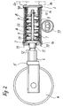
- the device shown in the drawing is preferably used for tensioning and cushioning the idler wheel of tracked vehicles. It consists of a mechanical spring unit 1 with clamping plates 2, 3 and a preferably hydraulic clamping unit 4. The device can be clamped between frame parts 5 of the stator 6 and frame parts of the vehicle frame (20).
- the spring unit 1 used is a unit consisting of concentrically arranged, alternating tensile and compressive rings with conical active surfaces, which in the exemplary embodiment consists of ten outer rings and nine inner rings and two half inner rings at the ends. The outer rings are designated 7 and the inner rings 8.
- the spring unit formed in this way is closely surrounded by a protective tube 9 which is fastened to the clamping plate 3 which can be fixed to the frame parts (20) of the vehicle frame and into which the clamping plate 2 which can be acted upon by the hydraulic clamping unit 4 can be inserted with increasing preload of the spring unit (7, 8) is.
- the protective tube 9 is closed at its vehicle frame end (on the right in the drawing) by the clamping plate 3 and at its other end by a cover plate 10, the cover plate 10 being screwed to the protective tube 9 and the clamping plate 3 being welded to the protective tube 9 (FIG 1 + 2) or the clamping plate 3 is screwed to the protective tube 9 and the cover plate 10 is welded on (FIG. 3).
- the cover plate 10 is penetrated by a plunger 11 of the clamping plate 2, on which a plunger 12 of the hydraulic clamping unit 4 acts.
- the preload of the spring unit can be changed by the screw connection or the screw-in depth of the cover plate 10 or clamping plate 3.
- the sliding clamping plate 2 is with a Tie rod 13 connected or formed in one piece, which consists of the inner and outer rings 7, 8 formed spring unit coaxially with great play be upheld.
- the tie rod 13 is on the frame-fixed clamping plate 3 indirectly displaceable supported, which will be explained later, its effects for the purpose of pre-tensioning of the spring unit due to assembly can be shortened, which is also explained later becomes.
- the axially displaceable end of the tie rod 13 is arranged in a on the clamping plate 3 Chamber 14 arranged, the length of which in the axial Extension of the tie rod 13 is greater than that corresponds to the maximum spring travel of the spring unit.
- the chamber 14 is by a pot-like part with protruding radially outward on the muzzle side Flange 18 formed.
- the flange 18 lies on the clamping plate 3 and the one there End face of the spring unit is supported on Flange 18 as an abutment.
- the end of the tie rod 13 is a clamping nut 15 screwed on so that the effective length of the tie rod can be shortened before final assembly.
- preload can be the spring unit are pressed together so that the corresponding clamping nut 15 increasingly on that End of the tie rod 13 can be screwed on, to secure the preload.
- the spring unit is then between the flange 18 of the Chamber forming part of the pot and Clamping plate 2 clamped and at 5 to 10% biased.
- the protective tube 9 can then be pushed onto the pre-assembled unit, until the welded to the protective tube
- the clamping plate 3 is supported on the flange 18.
- the cover plate 10 with the protective tube 9 9 screwed and the spring unit increasingly preloaded e.g. to 50% preload.
- the screw connection takes place at 19 indicated screw fastener.
- Tie rod is additionally one according to FIG. 1
- Guide or sealing disc 16 held the in the chamber 14 in the longitudinal direction is displaceable and which is on the Chamber wall leading over its entire circumference and / or also supports sealing.
- Below the Protective tube 9 is another one in the drawing Roller 17 indicated, via which the chain strand expires, which is guided over the stator 6 and at the other deflection point of the chain on the drive wheel circulates.
- Coil spring 22 can be the restoring forces Adjust spring unit so that a quick Rebound is achieved with relief and yet the impact forces are minimized.
- end flange 25 is then e.g. by means of Screws 19 tightened against the clamping plate 3, whereby the spring unit increasingly biased and the Nut 15 is relieved since the tie rod is now immerses increasingly deeper into the chamber 14, as in Fig. 3 is shown.
- the complete clamping unit is then inserted between the stator 6 or tappet 4 and the chassis frame 20.
- a piston 27 engages in the cavity 26 of the element 23.
- the piston 27 has at least one axial bore 28 which on the one hand has a grease nipple or the like 29 on the outside and is easily accessible and on the other hand opens out into the space 26.
Landscapes
- Engineering & Computer Science (AREA)
- Chemical & Material Sciences (AREA)
- Combustion & Propulsion (AREA)
- Transportation (AREA)
- Mechanical Engineering (AREA)
- Devices For Conveying Motion By Means Of Endless Flexible Members (AREA)
- Fluid-Damping Devices (AREA)
- Vehicle Body Suspensions (AREA)
- Yarns And Mechanical Finishing Of Yarns Or Ropes (AREA)
- Axle Suspensions And Sidecars For Cycles (AREA)
- Springs (AREA)
- Clamps And Clips (AREA)
Description
- Figur 1
- eine erfindungsgemäße Vorrichtung in Seitenansicht, teilweise geschnitten;
- Figur 2 und 3
- Varianten in gleicher Ansicht.
Die so gebildete Federeinheit ist von einem Schutzrohr 9 eng umfasst, welches an der an Gestellteilen (20) des Fahrzeugrahmens fixierbaren Spannplatte 3 befestigt ist und in welches die mit der hydraulischen Spanneinheit 4 beaufschlagbare Spannplatte 2 unter zunehmender Vorspannung der Federeinheit (7, 8)einschiebbar ist. Das Schutzrohr 9 ist an seinem fahrzeugrahmenseitigen Ende (in der Zeichnung rechts) durch die Spannplatte 3 und an seinem anderen Ende durch eine Deckplatte 10 verschlossen, wobei die Deckplatte 10 mit dem Schutzrohr 9 verschraubt und die Spannplatte 3 mit dem Schutzrohr 9 verschweißt ist (Fig. 1 + 2) oder die Spannplatte 3 mit dem Schutzrohr 9 verschraubt und die Deckplatte 10 angeschweißt ist (Fig. 3). Die Deckplatte 10 ist von einem Stößel 11 der Spannplatte 2 durchgriffen, auf die ein Stößel 12 der hydraulischen Spanneinheit 4 einwirkt. Durch die Verschraubung oder die Einschraubtiefe der Deckplatte 10 oder Spannplatte 3 kann die Vorspannung der Federeinheit verändert werden.
Die Kette 30 wird somit gespannt und die Spanneinheit befindet sich in Sollage.
Claims (9)
- Vorrichtung zum Spannen und Abfedern des Leitrades von Kettenfahrzeugen und dergleichen mit bandförmigen Elementen angetriebenen Fahrzeugen, oder des Leitrades (6) von Band- oder Kettenförderern, bestehend aus einer mechanischen Federeinheit (1) mit Spannplatten (2,3) sowie vorzugsweise einer hydraulischen Spanneinheit (4), wobei die Vorrichtung zwischen Gestellteilen (5) des Leitrades (6) und des Rahmens des Fahrzeuges oder des Förderers einspannbar ist, dadurch gekennzeichnet, dass die Federeinheit aus konzentrisch angeordneten, abwechselnd zug- und druckbeanspruchten Ringen mit konischen Wirkflächen mit mehreren koaxial zueinander angeordneten Außenringen (7) und Innenringen (8) oder aus mehreren zueinander koaxial angeordneten ineinander gesetzten oder aneinander gesetzten solchen Federeinheiten oder mehreren parallel zueinander angeordneten solchen Federeinheiten besteht.
- Vorrichtung nach Anspruch 1, dadurch gekennzeichnet, dass Federeinheiten mit mindestens acht Außenringen (7) und Innenringen (8) verwendet werden.
- Vorrichtung nach Anspruch 1 oder 2, dadurch gekennzeichnet, dass die Federeinheit oder Federeinheiten von einem Schutzrohr (9) eng umfasst ist oder sind, welches an der an Gestellteilen (20) des Fahrzeugrahmens fixierbaren Spannplatte (3) befestigt ist und in welches die mit der hydraulischen Spanneinheit (4) beaufschlagbare Spannplatte (2) unter zunehmender Vorspannung der Federeinheit einschiebbar ist.
- Vorrichtung nach Anspruch 3, dadurch gekennzeichnet, dass das Schutzrohr (9) an seinem fahrzeugrahmenseitigen Ende durch die Spannplatte (3) und an seinem dem Leitrad (6) zugewandten Ende durch eine anschraubbare Deckplatte (10) verschlossen ist, wobei die Deckplatte (10) von einem Stößel (11) der anderen Spannplatte (2) oder von einem auf diese einwirkenden Stößel der hydraulischen Spanneinheit (4) durchgriffen oder durchgreifbar ist.
- Vorrichtung nach einem der Ansprüche 1 bis 4, dadurch gekennzeichnet,dass die verschiebliche Spannplatte (2) einen Zuganker (13) aufweist, der an der rahmenfesten Spannplatte (3) axial verschieblich gehaltert und dessen Wirklänge zum Zwecke der Einstellung der Vorspannung der Federeinheit verkürzbar ist.
- Vorrichtung nach Anspruch 5, dadurch gekennzeichnet, dass das axial verschiebliche Ende des als Stange oder Rohr ausgebildeten Zugankers (13) in einer an der Spannplatte (3) ausgebildeten Kammer (14) angeordnet ist, deren Länge (in axialer Erstreckung des Zugankers (13) ) mindestens gleich oder auch größer ist als dem maximalen Federweg entspricht, wobei auf das in der Kammer (14) befindliche Ende des Zugankers (13) eine Spannmutter (15) aufgeschraubt ist, die sich an Kammerteilen als Widerlager unmittelbar oder mittelbar abstützt, und wobei die Kammer (14) durch eine topfartige Hülse mit Außenflansch (18) gebildet ist, deren Flansch (18) sich an der Spannplatte (3) abstützt und an deren Flansch (18) sich das Ende der Federeinheit abstützt.
- Vorrichtung nach Anspruch 6,
dadurch gekennzeichnet, dass am Ende des Zugankers (13) eine Führungs- und/oder Dichtscheibe (16) gehaltert ist, die in der Kammer (14) in deren Längsrichtung verschieblich ist und die sich an der Kammerwandung über ihren gesamten Umfang führend und/oder dichtend abstützt. - Vorrichtung nach einem der Ansprüche 1 bis 7,
dadurch gekennzeichnet, dass konzentrisch zur Federeinheit (7,8) mindestens eine in gleicher Richtung beanspruchbare Schraubenfeder (22) angeordnet ist, die sich an der Spannplatte (2) und unmittelbar oder mittelbar unter Zwischenanordnung des Teiles (14) an der Spannplatte (3) abstützt. - Vorrichtung nach einem der Ansprüche 1 bis 8,
dadurch gekennzeichnet, dass die Vorrichtung gestellseitig (bei 20) mittels eines Fettspanners längsverstellbar, parallel zu den Kettentrums der Kette (30), gehaltert ist.
Applications Claiming Priority (2)
| Application Number | Priority Date | Filing Date | Title |
|---|---|---|---|
| DE19538222 | 1995-10-13 | ||
| DE19538222 | 1995-10-13 |
Publications (3)
| Publication Number | Publication Date |
|---|---|
| EP0788966A2 EP0788966A2 (de) | 1997-08-13 |
| EP0788966A3 EP0788966A3 (de) | 1998-10-21 |
| EP0788966B1 true EP0788966B1 (de) | 2003-04-23 |
Family
ID=7774816
Family Applications (1)
| Application Number | Title | Priority Date | Filing Date |
|---|---|---|---|
| EP96114922A Expired - Lifetime EP0788966B1 (de) | 1995-10-13 | 1996-09-18 | Vorrichtung zum Spannen und Abfedern des Leitrades von Kettenfahrzeugen |
Country Status (5)
| Country | Link |
|---|---|
| US (1) | US5851058A (de) |
| EP (1) | EP0788966B1 (de) |
| JP (1) | JP3036374U (de) |
| AT (1) | ATE238191T1 (de) |
| DE (2) | DE59610379D1 (de) |
Families Citing this family (16)
| Publication number | Priority date | Publication date | Assignee | Title |
|---|---|---|---|---|
| FR2772857B1 (fr) * | 1997-12-18 | 2000-02-11 | Hutchinson | Tendeur, moteur comportant un tel tendeur et procede de montage d'un tel tendeur |
| FR2788825B1 (fr) * | 1999-01-25 | 2001-03-09 | Hutchinson | Tendeur pour courroie, circuit cinematique et moteur comportant un tel tendeur |
| US6662421B1 (en) | 2001-06-25 | 2003-12-16 | Joe Krippelz, Sr. | Method and apparatus for installation of rubber tracks on vehicles |
| ITTO20070364A1 (it) * | 2007-05-23 | 2008-11-24 | Cnh Italia Spa | Dispositivo di trazione a cingolo |
| EP2428436B1 (de) | 2010-09-14 | 2014-11-05 | Joseph Vögele AG | Raupenfahrwerk |
| US8764129B2 (en) | 2011-05-27 | 2014-07-01 | Gse Technologies, Llc | Track over tire system and method |
| CN103085903A (zh) * | 2013-01-20 | 2013-05-08 | 西南交通大学 | 一种履带涨紧装置 |
| CN103291797B (zh) * | 2013-03-15 | 2016-01-20 | 尹学军 | 一种摩擦阻尼器 |
| KR101692260B1 (ko) * | 2013-06-27 | 2017-01-04 | 동국대학교 산학협력단 | 가스 하이드레이트 펠릿 성형장치 |
| US10113656B2 (en) * | 2015-04-29 | 2018-10-30 | Clark Equipment Company | Track tensioner |
| US11208165B2 (en) * | 2017-08-02 | 2021-12-28 | Joy Global Surface Mining Inc | Passive track tensioning system |
| CN107984066B (zh) * | 2017-11-30 | 2020-03-31 | 中国航发沈阳黎明航空发动机有限责任公司 | 一种用于氩弧焊接环形焊缝的双侧同步涨紧机构 |
| US11097794B2 (en) | 2019-02-14 | 2021-08-24 | Srj, Inc. | Roller suspension system |
| US12030568B2 (en) * | 2020-01-17 | 2024-07-09 | Barreto Manufacturing, Inc. | Hydraulic tensioning system for track drive vehicle |
| CN118622922A (zh) * | 2020-06-09 | 2024-09-10 | 阿什琳·安东尼 | 用于消除链条传动装置的链条中的松弛和振动的设备 |
| CN113771977A (zh) * | 2021-10-01 | 2021-12-10 | 安翼机器人(江苏)有限公司 | 一种履带机器人用张紧调节机构 |
Family Cites Families (12)
| Publication number | Priority date | Publication date | Assignee | Title |
|---|---|---|---|---|
| DE456065C (de) * | 1926-10-15 | 1928-02-14 | Wilhelm Wurl | Ringfeder |
| US2506619A (en) * | 1947-06-06 | 1950-05-09 | Silver Booster Mfg Co | Coupling for tension bolts |
| US3008772A (en) * | 1959-01-05 | 1961-11-14 | Sr Joseph C Helsel | Track tension adjuster |
| CH362326A (fr) * | 1959-06-29 | 1962-05-31 | Brevets Aero Mecaniques | Dispositif de suspension pour galet de roulement d'un véhicule à chenilles |
| DE1190344B (de) * | 1962-07-28 | 1965-04-01 | Kloeckner Humboldt Deutz Ag | Spannvorrichtung fuer die Gleisketten von Fahrzeugen |
| US3826543A (en) * | 1972-10-13 | 1974-07-30 | Caterpillar Tractor Co | Track tensioning and recoil apparatus |
| US3829172A (en) * | 1972-12-11 | 1974-08-13 | Caterpillar Tractor Co | Recoil mechanism for track-type tractors |
| DE2741105C3 (de) * | 1977-09-13 | 1980-09-25 | Intertrac Viehmann & Co, 5820 Gevelsberg | Federspannelement für das Leitrad von Gleiskettenfahrzeugen |
| DE2758856C2 (de) * | 1977-12-30 | 1986-09-25 | Conducta Gesellschaft für Meß- und Regeltechnik mbH & Co, 7016 Gerlingen | Meßwertumformer, insbesondere für direkt messende Betriebsanalysengeräte |
| US4650259A (en) * | 1985-11-12 | 1987-03-17 | Caterpillar Inc. | Method and apparatus for tensioning ground engaging endless elastomeric belts |
| DE4025929C2 (de) * | 1990-08-16 | 1999-07-08 | Intertractor Ag | Spannvorrichtung für das Leitrad von Kettenfahrzeugen |
| DE29606295U1 (de) * | 1996-04-04 | 1996-07-04 | Joseph Vögele AG, 68163 Mannheim | Vorrichtung zum Spannen und Abfedern des Leitrades in einem Kettenfahrwerk und Straßenfertiger |
-
1996
- 1996-09-18 AT AT96114922T patent/ATE238191T1/de not_active IP Right Cessation
- 1996-09-18 EP EP96114922A patent/EP0788966B1/de not_active Expired - Lifetime
- 1996-09-18 DE DE59610379T patent/DE59610379D1/de not_active Expired - Fee Related
- 1996-09-18 DE DE29616216U patent/DE29616216U1/de not_active Expired - Lifetime
- 1996-10-01 JP JP1996011224U patent/JP3036374U/ja not_active Expired - Lifetime
- 1996-10-11 US US08/728,952 patent/US5851058A/en not_active Expired - Fee Related
Also Published As
| Publication number | Publication date |
|---|---|
| DE59610379D1 (de) | 2003-05-28 |
| ATE238191T1 (de) | 2003-05-15 |
| US5851058A (en) | 1998-12-22 |
| JP3036374U (ja) | 1997-04-15 |
| EP0788966A3 (de) | 1998-10-21 |
| EP0788966A2 (de) | 1997-08-13 |
| DE29616216U1 (de) | 1996-11-14 |
Similar Documents
| Publication | Publication Date | Title |
|---|---|---|
| EP0788966A2 (de) | Vorrichtung zum Spannen und Abfedern des Leitrades von Kettenfahrzeugen | |
| DE102007015975B4 (de) | Hydraulische Spannvorrichtung zum Spannen von Schrauben | |
| DE3928016C2 (de) | Riemen- oder Kettenspanner | |
| WO2013160063A1 (de) | Halter zur befestigung einer komponente an einer brennkraftmaschine | |
| DE102018205184A1 (de) | Dichtungsvorrichtung und Hydraulikkolben mit Dichtungsvorrichtung | |
| DE2741105B2 (de) | Federspannelement für das Leitrad von Gleiskettenfahrzeugen | |
| EP0707549B1 (de) | Vorrichtung zum spannen und abfedern des leitrades von kettenfahrzeugen | |
| DE3838995C2 (de) | ||
| EP1136346B1 (de) | Verbindungselement für eine elastische Verbindung zweier Bauteile | |
| DE4025929A1 (de) | Spannvorrichtung fuer das leitrad von kettenfahrzeugen | |
| DE102005043095A1 (de) | Vorrichtung und Verfahren zum torsionsfreien Spannen eines Bolzens | |
| EP2604361B1 (de) | Spannkeilvorrichtung zur Befestigung von Werkzeugen an Werkzeugmaschinen | |
| DE102006016826B4 (de) | Öffnungsvorrichtung für eine Klappe | |
| DE202017005337U1 (de) | Spannvorrichtung für eine (Gelenk-)Kette und Montagesatz damit | |
| DE19858419A1 (de) | Federspanner für eine Schraubenfeder eines Fahrzeugfederbeins | |
| DE102014203947A1 (de) | Schraubtriebspanner aus Blech | |
| DE3906787A1 (de) | Mechanische spanneinrichtung | |
| DE102006032368B4 (de) | Spannvorrichtung | |
| DE202010014188U1 (de) | Spannvorrichtung für Zugmittelantriebe, insbesondere drehrichtungswechselnde Ketten- oder Riemenantriebe | |
| DE69410953T2 (de) | Zahnstangenlenkung für Kraftfahrzeuge | |
| DE10360288A1 (de) | Mechanische Spannvorrichtung für Zugmittel mit gerichteter Reibdämpfung | |
| DE1190344B (de) | Spannvorrichtung fuer die Gleisketten von Fahrzeugen | |
| EP0799760A1 (de) | Vorrichtung zum Spannen und Abfedern des Leitrades in einem Kettenfahrwerk und Strassenfertiger | |
| DE3404517A1 (de) | Elastomer-kettenspanner fuer kettenfahrzeuge | |
| DE202004002705U1 (de) | Spannvorrichtung mit zusätzlichem druckabhängigen Dämpfungselement |
Legal Events
| Date | Code | Title | Description |
|---|---|---|---|
| PUAI | Public reference made under article 153(3) epc to a published international application that has entered the european phase |
Free format text: ORIGINAL CODE: 0009012 |
|
| AK | Designated contracting states |
Kind code of ref document: A2 Designated state(s): AT DE FR GB IT NL SE |
|
| PUAL | Search report despatched |
Free format text: ORIGINAL CODE: 0009013 |
|
| AK | Designated contracting states |
Kind code of ref document: A3 Designated state(s): DE FR GB IT SE |
|
| RBV | Designated contracting states (corrected) |
Designated state(s): AT DE FR GB IT NL SE |
|
| 17P | Request for examination filed |
Effective date: 19990127 |
|
| 17Q | First examination report despatched |
Effective date: 20010131 |
|
| GRAH | Despatch of communication of intention to grant a patent |
Free format text: ORIGINAL CODE: EPIDOS IGRA |
|
| GRAH | Despatch of communication of intention to grant a patent |
Free format text: ORIGINAL CODE: EPIDOS IGRA |
|
| RAP1 | Party data changed (applicant data changed or rights of an application transferred) |
Owner name: INTERTRACTOR GMBH |
|
| GRAA | (expected) grant |
Free format text: ORIGINAL CODE: 0009210 |
|
| AK | Designated contracting states |
Designated state(s): AT DE FR GB IT NL SE |
|
| PG25 | Lapsed in a contracting state [announced via postgrant information from national office to epo] |
Ref country code: NL Free format text: LAPSE BECAUSE OF FAILURE TO SUBMIT A TRANSLATION OF THE DESCRIPTION OR TO PAY THE FEE WITHIN THE PRESCRIBED TIME-LIMIT Effective date: 20030423 Ref country code: GB Free format text: LAPSE BECAUSE OF FAILURE TO SUBMIT A TRANSLATION OF THE DESCRIPTION OR TO PAY THE FEE WITHIN THE PRESCRIBED TIME-LIMIT Effective date: 20030423 |
|
| REG | Reference to a national code |
Ref country code: GB Ref legal event code: FG4D Free format text: NOT ENGLISH |
|
| REF | Corresponds to: |
Ref document number: 59610379 Country of ref document: DE Date of ref document: 20030528 Kind code of ref document: P |
|
| PG25 | Lapsed in a contracting state [announced via postgrant information from national office to epo] |
Ref country code: SE Free format text: LAPSE BECAUSE OF FAILURE TO SUBMIT A TRANSLATION OF THE DESCRIPTION OR TO PAY THE FEE WITHIN THE PRESCRIBED TIME-LIMIT Effective date: 20030723 |
|
| PGFP | Annual fee paid to national office [announced via postgrant information from national office to epo] |
Ref country code: AT Payment date: 20030930 Year of fee payment: 8 |
|
| NLV1 | Nl: lapsed or annulled due to failure to fulfill the requirements of art. 29p and 29m of the patents act | ||
| GBV | Gb: ep patent (uk) treated as always having been void in accordance with gb section 77(7)/1977 [no translation filed] |
Effective date: 20030423 |
|
| ET | Fr: translation filed | ||
| PLBE | No opposition filed within time limit |
Free format text: ORIGINAL CODE: 0009261 |
|
| STAA | Information on the status of an ep patent application or granted ep patent |
Free format text: STATUS: NO OPPOSITION FILED WITHIN TIME LIMIT |
|
| 26N | No opposition filed |
Effective date: 20040126 |
|
| PGFP | Annual fee paid to national office [announced via postgrant information from national office to epo] |
Ref country code: FR Payment date: 20040813 Year of fee payment: 9 |
|
| PG25 | Lapsed in a contracting state [announced via postgrant information from national office to epo] |
Ref country code: AT Free format text: LAPSE BECAUSE OF NON-PAYMENT OF DUE FEES Effective date: 20040918 |
|
| PGFP | Annual fee paid to national office [announced via postgrant information from national office to epo] |
Ref country code: DE Payment date: 20041130 Year of fee payment: 9 |
|
| PG25 | Lapsed in a contracting state [announced via postgrant information from national office to epo] |
Ref country code: DE Free format text: LAPSE BECAUSE OF NON-PAYMENT OF DUE FEES Effective date: 20060401 |
|
| PG25 | Lapsed in a contracting state [announced via postgrant information from national office to epo] |
Ref country code: FR Free format text: LAPSE BECAUSE OF NON-PAYMENT OF DUE FEES Effective date: 20060531 |
|
| REG | Reference to a national code |
Ref country code: FR Ref legal event code: ST Effective date: 20060531 |
|
| PGFP | Annual fee paid to national office [announced via postgrant information from national office to epo] |
Ref country code: IT Payment date: 20080926 Year of fee payment: 13 |
|
| PG25 | Lapsed in a contracting state [announced via postgrant information from national office to epo] |
Ref country code: IT Free format text: LAPSE BECAUSE OF NON-PAYMENT OF DUE FEES Effective date: 20090918 |