EP0789105B1 - Sèche linge avec porte de type à panneau frontal et avec réservoir extractible pour collecter l'eau condensée - Google Patents
Sèche linge avec porte de type à panneau frontal et avec réservoir extractible pour collecter l'eau condensée Download PDFInfo
- Publication number
- EP0789105B1 EP0789105B1 EP96202695A EP96202695A EP0789105B1 EP 0789105 B1 EP0789105 B1 EP 0789105B1 EP 96202695 A EP96202695 A EP 96202695A EP 96202695 A EP96202695 A EP 96202695A EP 0789105 B1 EP0789105 B1 EP 0789105B1
- Authority
- EP
- European Patent Office
- Prior art keywords
- tank
- cassette
- laundry
- door
- drying machine
- Prior art date
- Legal status (The legal status is an assumption and is not a legal conclusion. Google has not performed a legal analysis and makes no representation as to the accuracy of the status listed.)
- Expired - Lifetime
Links
- 238000009833 condensation Methods 0.000 title claims description 15
- 230000005494 condensation Effects 0.000 title claims description 15
- XLYOFNOQVPJJNP-UHFFFAOYSA-N water Substances O XLYOFNOQVPJJNP-UHFFFAOYSA-N 0.000 title claims description 14
- 238000001035 drying Methods 0.000 claims description 28
- 238000011068 loading method Methods 0.000 claims description 17
- 238000011049 filling Methods 0.000 claims description 14
- 239000007788 liquid Substances 0.000 claims description 13
- 238000000605 extraction Methods 0.000 claims description 3
- 230000005484 gravity Effects 0.000 claims 1
- 239000003570 air Substances 0.000 description 12
- 238000009825 accumulation Methods 0.000 description 2
- 230000015572 biosynthetic process Effects 0.000 description 2
- 238000010438 heat treatment Methods 0.000 description 2
- 238000007789 sealing Methods 0.000 description 2
- 239000012080 ambient air Substances 0.000 description 1
- 238000004140 cleaning Methods 0.000 description 1
- 238000004891 communication Methods 0.000 description 1
- 238000001816 cooling Methods 0.000 description 1
- 238000010981 drying operation Methods 0.000 description 1
- 238000001704 evaporation Methods 0.000 description 1
- 230000008020 evaporation Effects 0.000 description 1
- 239000004744 fabric Substances 0.000 description 1
- 238000003780 insertion Methods 0.000 description 1
- 230000037431 insertion Effects 0.000 description 1
- 238000013021 overheating Methods 0.000 description 1
- 230000035515 penetration Effects 0.000 description 1
- 238000003303 reheating Methods 0.000 description 1
- 238000000926 separation method Methods 0.000 description 1
- 125000006850 spacer group Chemical group 0.000 description 1
- 239000012780 transparent material Substances 0.000 description 1
Images



Classifications
-
- D—TEXTILES; PAPER
- D06—TREATMENT OF TEXTILES OR THE LIKE; LAUNDERING; FLEXIBLE MATERIALS NOT OTHERWISE PROVIDED FOR
- D06F—LAUNDERING, DRYING, IRONING, PRESSING OR FOLDING TEXTILE ARTICLES
- D06F58/00—Domestic laundry dryers
- D06F58/20—General details of domestic laundry dryers
- D06F58/22—Lint collecting arrangements
-
- D—TEXTILES; PAPER
- D06—TREATMENT OF TEXTILES OR THE LIKE; LAUNDERING; FLEXIBLE MATERIALS NOT OTHERWISE PROVIDED FOR
- D06F—LAUNDERING, DRYING, IRONING, PRESSING OR FOLDING TEXTILE ARTICLES
- D06F58/00—Domestic laundry dryers
- D06F58/20—General details of domestic laundry dryers
- D06F58/24—Condensing arrangements
Definitions
- the present invention relates to the laundry-drying machines of the domestic type, with a panel-type front door and extractable tank for collecting the condensation water.
- Front-loading laundry-drying machines are known, both of the type in which the loading opening is closed by a porthole and of the type in which the loading opening is closed by a continuous panel which covers the entire front surface of the machine excluding the single control panel and a lower base.
- EP-A-0 555 703 discloses an arrangement according to the preamble of claim 1.
- the tank is provided, on its upper face, with a filling opening which freely faces, when the door is closed, a pipe for supplying condensation water, without the use of sealing connections or overflow pressure switches.
- the cassette housing of the tank also constitutes a section of the drying circuit leaving the rotating basket for containing the laundry, which is closed by a perforated protection diaphragm and in which, interposed between diaphragm and collecting tank, there is accommodated a filter for catching fluff, which can be removed separately from said tank and cleaned easily.
- a first seal arranged all around the loading opening ensures, when the door is closed, the sealing of the drying circuit from the outside.
- a second seal arranged inside the loading opening, mates with the internal diaphragm, isolating the section of the drying circuit leaving the rotating basket from the volume of the basket.
- the tank is provided with means which reduce to a minimum or eliminate the risk of overflows during handling of the tank.
- the laundry-drying machine comprises essentially a rotating drum or basket 1 which holds the laundry, is set in rotation by a motor 2 and passed through by a flow of air which is introduced into the drum 1 by a centrifugal fan 3 and is subject to heating by heating elements 4.
- the laundry contained in the drum 1 releases, by evaporation, the humidity which it contains to the flow of hot air.
- the hot humid air leaves the drum through a filter 5 (which retains flying down and fluff) and is conveyed by an appropriate pipe entering a condenser 6 which is cooled by a flow of relatively cold air drawn in from the atmosphere by means of a centrifugal aspirator 7.
- the vapour contained in the flow of hot air is condensed to liquid by cooling and collects in a condenser reservoir 8 arranged below the level of a door for closing the loading opening, while the dehumidified air leaving the condenser 6 is drawn by the fan 3 and made to recirculate in the drum 1, subject to reheating.
- the flow of ambient air used for the condensation is on the other hand dispersed into the atmosphere.
- the condensation liquid collected in the reservoir 8 is conveyed, by means of a pump 9, into a collecting tank 10 which is arranged at a higher level relative to that of the condenser.
- a level sensor 11 acts if the level of liquid in the reservoir exceeds a predetermined value, stopping the operation of the machine.
- the operation of the machine is controlled by a programmer 12 which is actuated by buttons or knobs 13 arranged on a front control panel 14.
- the loading opening 16 in the front wall is defined by a collar 17 which extends internally from the front wall 15 to be connected, by a labyrinth seal, to a front rim 18 of the rotating drum 1.
- aspiration openings 19 open, which are connected to an aspiration pipe 20 which conveys the humid air leaving the rotating drum to the condenser 6.
- the external edge and the internal edge of the collar are expediently provided with a resilient seal 22, 23 respectively.
- the door for closing the loading opening which is hinged on the front wall, is formed by a flat external front panel 24 and by an internal counter-panel 25 which has a flat frame which, when the door is closed, is juxtaposed to the seal 22 bringing about the sealed closing of the loading opening.
- the counter-panel forms a sleeve 26 which projects internally and is accommodated in the collar of the loading opening and the external wall of which is juxtaposed, when the door is closed, to the seal 23.
- a housing 27 or containing cassette Formed inside the sleeve is a housing 27 or containing cassette, which is generally cylindrical but can be prismatic, for a tank 10 for collecting the condensation water, which can be removed from the cassette in the direction of the housing axis represented by the arrow 28 and inserted by translation in the opposite direction.
- a perforated cover 29 is hinged, which constitutes a separation diaphragm between the internal volume of the rotating drum 1 and the cylindrical housing 27 to prevent the penetration of the laundry to be dried into the housing 27 during operation of the machine.
- a filter 5 for catching the down and fluff shed by the laundry is removably engaged.
- the filter 5 is expediently provided with a knob 31 or equivalent means for its extraction from the cover 29 in the direction represented by the arrow 32.
- the knob 31 also serves as a spacer and, by bearing against the wall of the tank 10, ensures the formation, between filter and tank, of an air chamber, through which the hot humid air which passes through the filter can flow towards the aspiration pipe 20, through expedient openings 34 formed in the lower wall of the sleeve.
- the sleeve 26 is provided on its upper wall with a funnel-shaped opening 33 which brings the outside of the sleeve into communication with the internal housing 27 and, when the door is closed, faces the nozzle 21 for discharge of the condensation water.
- the tank 10 is expediently provided with a handle 35 for extraction/insertion and, on its upper face, with a filling mouth 36 which, when the tank is inserted in its housing, is juxtaposed freely, in other words without any device for valve-type closing or sealed connection to a delivery pipe, to the funnel-shaped opening 33.
- the filling mouth therefore functions jointly as a filling opening and a vent opening and prevents the tank becoming pressurized during filling.
- the tank 10 is provided on one side and on the upper wall with a recessed groove 37 which extends from the filling mouth 36 to the lower wall of the tank in such a manner that, when the tank is full, the excess liquid conveyed into the tank can freely overflow from the mouth 36 and flow along the groove 37 to the lower wall of the sleeve 26 where, passing through the openings 34, it is conveyed into the condenser 6 and discharged into the reservoir 8.
- the operation of the laundry-drying machine described is very simple: by opening the loading door, the operator can insert the laundry to be dried into the rotating drum, check that the filter 5 is clean and, if necessary, clean it by opening the cover 29 and removing the filter independently of the tank.
- tank 10 expediently made to this end of transparent material, is empty and, if necessary, remove it and empty it.
- the filter When the tank has been reinserted into its housing, the filter has been reinserted into the cover 29 and the cover has been reclosed, the door can be reclosed and the operation of the drier can be started.
- the condensation liquid leaving the nozzle 21 is discharged into the housing 27 and, conveyed back into the condenser reservoir, brings about the action of the protection, in the same manner, at the very beginning of the drying operation.
- the operator alerted by the action of the protection, can easily recognize, by opening the loading door, the full state of the tank or its absence from the housing.
- the structure of the machine is therefore very simple and extremely reliable and at the same time particularly ergonomic and convenient to operate.
- the removability of the filter independently of the collecting tank allows it to be handled easily, unaffected by the weight of the tank, for thorough cleaning, if necessary under a jet of water, without risk of damage.
- the removal of the tank for emptying can be carried out without special precautions, except those which are necessary in order to avoid any overflows if the tank is completely full.
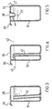
- Figures 3, 4 and 5 represent a number of measures which reduce to a minimum or eliminate the risk of any overflows during removal of the tank.
- the tank 10 is provided internally with an overflow tube 40 which is open on the lower wall of the tank and the top of which ends close to the handle 35 for extracting the tank from its housing. Since the handle is eccentric relative to the barycentric vertical axis of the tank, the tank tends, during its removal from the cassette housing, to rotate slightly to be arranged with its barycentre vertically aligned with the gripping handle.
- the overflow tube 40 can advantageously be replaced by a siphon 41 which comes into action when the level of the liquid in the tank reaches the threshold 42 of the siphon and brings about the partial emptying of the tank to the level of the mouth 43 for feeding the siphon.
- the mouth 36 for filling the tank 10 is provided with a funnel-shaped sleeve 44 which penetrates a convenient depth into the tank.
- the maximum pressurization which can be exerted is determined in terms of water column, by the difference between the overflow level of the mouth 36 and the filling level of the tank.
- vent opening 46 which is normally closed when the tank 10 is correctly installed in its housing by a resilient plug 47 arranged in the housing, on the first movement of the tank 10 for its removal, the opening 46 is opened, drawing back into the tank the liquid contained in the sleeve 44.
- the resilient plug 47 can be mounted on the filter 5 and the vent 46 can be provided on the wall of the tank facing the filter in such a manner that opening the cover 29 brings about opening of the vent, still before the tank is removed from its housing.
- Fig. 6 represents an alternative embodiment of the laundry-drying machine in Figs 1 and 2, in which, inside the front closing door, the counter-panel 25 forms a cassette 27 or pocket housing for the tank and filter, which is open at the top.
- the perforated diaphragm 50 for clsing the cassette is an integral part and steady with the counter-panel itself.
- the filter 5 provided with a spacing frame 30 and an upper handle 48, is arranged in the cassette 27 in an interposed position between the perforated diaphragm 50 and the tank 10 which is provided with an upper handle 49 and a filling mouth 36.
- the tank is expediently shaped to allow its removal from the cassette by slight rotation and translation upwards, subject to removal of the filter 30, so as to utilize (as in the case of Figs 1 and 2) the volume offered by the thickness of the closing door.
- the filter is inspected upon each operation to remove the tank, avoiding subsequent disadvantages (reduction of the drying efficiency, greater wear of the fan and overheating of the recirculation air).
Landscapes
- Engineering & Computer Science (AREA)
- Textile Engineering (AREA)
- Detail Structures Of Washing Machines And Dryers (AREA)
- Body Structure For Vehicles (AREA)
Claims (7)
- Sèche-linge pourvu d'une trappe avant (24, 25, 26) formée par un panneau externe plat (24) destiné à fermer l'ouverture de chargement (16) et par un contre-panneau interne (25), et d'un réservoir (10) destiné à collecter le condensat et reçu dans la dite trappe (24, 25, 26), le dit sèche-linge étant équipé d'un tambour tournant (1) destiné à contenir le linge et d'un réservoir (8) de condenseur (6) qui est disposé au-dessous du niveau de la dite trappe avant, comprenant :caractérisé en ce queune buse (21), destinée à amener l'eau de condensation, qui débouche librement dans la dite ouverture de chargement (16),une cassette (27) destinée à loger un réservoir de collecte (10), laquelle cassette est formée dans le dit contre-panneau interne (25), pourvue à la partie supérieure d'une ouverture (33) qui, quand la trappe est fermée, fait face à la dite buse (21),un réservoir (10) destiné à collecter l'eau de condensation, qui est reçu dans la dite cassette (27) et qui peut être retiré de la dite cassette uniquement lorsque la trappe est ouverte, le dit réservoir (10) étant équipé, sur sa face supérieure, d'une embouchure de remplissage (36) qui fait librement face à la dite buse d'amenée (21), lorsque la dite trappe avant est fermée,un diaphragme perforé (29, 47, 50) associé à la dite cassette (27) afin de séparer le volume du dit tambour (1) du volume de la dite cassette (27), etun filtre (5) destiné à piéger les peluches, qui est reçu dans la dite cassette (27), interposé entre le dit réservoir (10) et le dit diaphragme (29, 47, 50),
la dite cassette (27) est pourvue, à la partie inférieure, de moyens (34, 20) aptes à acheminer un trop-plein de liquide dans le dit réservoir (8) de condenseur par gravité,
et en ce que
le filtre (5) peut être retiré de la cassette (27) indépendamment du dit réservoir (10) uniquement lorsque la trappe est ouverte. - Sèche-linge selon la revendication 1, dans lequel le dit contre-panneau interne (25) forme un manchon (26) à l'intérieur duquel la dite cassette (27) est formée, le dit diaphragme (29) est mis en articulation sur un bord du manchon (26) de manière à prendre une position qui permette la fermeture de la dite cassette et une position dans laquelle la cassette est ouverte, et le dit filtre (5) est monté, de façon amovible, sur l'intérieur du dit diaphragme (29) et peut être retiré lorsque la trappe est ouverte, et dans lequel :le dit réservoir (10) peut être extrait de la dite cassette suivant une direction perpendiculaire à la surface plate du dit panneau (24), dans la dite position d'ouverture de la dite cassette (27).
- Sèche-linge selon la revendication 1, dans lequel le dit logement de cassette (27) est ouvert à la partie supérieure et le dit filtre (5) et le dit réservoir (10) peuvent être extraits séparément de la dite cassette par mouvement de translation vers le haut.
- Sèche-linge selon la revendication 3, dans lequel le dit réservoir (10) peut être extrait du dit logement de cassette (27), à la condition unique que le dit filtre (5) soit extrait de la dite cassette.
- Sèche-linge selon la revendication 1, 2, 3 ou 4, dans lequel le dit réservoir (10) est équipé, à l'intérieur, d'un tube de trop-plein (40) qui est ouvert à la partie inférieure du dit réservoir (10).
- Sèche-linge selon la revendication 1, 2, 3 ou 4, dans lequel le dit réservoir (10) est équipé d'un siphon interne (41) destiné au trop-plein et à la vidange partielle, qui est ouvert à la partie inférieure du dit réservoir (10).
- Sèche-linge selon la revendication 1, 2, 3 ou 4, dans lequel le dit réservoir (10) est équipé de moyens (44) de mise sous pression d'un volume à la partie supérieure du dit réservoir, et de moyens (46) de dépressurisation du dit volume à la partie supérieure, qui peuvent être actionnés lors du retrait du dit réservoir (10) de la dite cassette.
Applications Claiming Priority (2)
| Application Number | Priority Date | Filing Date | Title |
|---|---|---|---|
| IT1996MI000095U IT240433Y1 (it) | 1996-02-06 | 1996-02-06 | Asciugabiancheria con sportello frontale a pannello e serbatoioestraibile di recupero dell'acqua di condensa |
| ITMI960095U | 1996-02-06 |
Publications (2)
| Publication Number | Publication Date |
|---|---|
| EP0789105A1 EP0789105A1 (fr) | 1997-08-13 |
| EP0789105B1 true EP0789105B1 (fr) | 2001-11-28 |
Family
ID=11372967
Family Applications (1)
| Application Number | Title | Priority Date | Filing Date |
|---|---|---|---|
| EP96202695A Expired - Lifetime EP0789105B1 (fr) | 1996-02-06 | 1996-09-26 | Sèche linge avec porte de type à panneau frontal et avec réservoir extractible pour collecter l'eau condensée |
Country Status (2)
| Country | Link |
|---|---|
| EP (1) | EP0789105B1 (fr) |
| IT (1) | IT240433Y1 (fr) |
Families Citing this family (28)
| Publication number | Priority date | Publication date | Assignee | Title |
|---|---|---|---|---|
| KR20030041385A (ko) * | 2001-11-20 | 2003-05-27 | (주)이젠텍 | 의류건조기 |
| KR100487759B1 (ko) * | 2003-08-13 | 2005-05-06 | 엘지전자 주식회사 | 의류건조기의 냉각공기 흡입구조 |
| AU2004240201B2 (en) * | 2003-12-22 | 2010-06-10 | Lg Electronics Inc. | Condensed water storing apparatus of a dryer |
| KR101093988B1 (ko) * | 2004-06-05 | 2011-12-15 | 엘지전자 주식회사 | 건조기의 도어 린트 필터 밀착 장치 |
| KR101137319B1 (ko) | 2004-11-15 | 2012-04-19 | 엘지전자 주식회사 | 응축식 의류건조기의 리버서블 도어 구조 |
| KR101094548B1 (ko) | 2005-01-25 | 2011-12-19 | 엘지전자 주식회사 | 건조기의 필터 구조 |
| KR101143685B1 (ko) | 2005-07-11 | 2012-05-09 | 엘지전자 주식회사 | 건조기의 필터 구조 |
| DE102006004589B4 (de) | 2006-02-01 | 2018-11-22 | BSH Hausgeräte GmbH | Einschub- und Grenz-Füllstandskontrolleinrichtung eines Haushalt-Wäschetrockners und Haushalt-Wäschetrockner |
| ATE519884T1 (de) * | 2006-09-29 | 2011-08-15 | Electrolux Home Prod Corp | Wäschetrockner mit einem in der tür montierten kondensatsammelbehälter |
| EP1936022A1 (fr) * | 2006-12-22 | 2008-06-25 | Electrolux Home Products Corporation N.V. | Sèche-linge |
| EP2167720B1 (fr) | 2007-06-07 | 2014-03-12 | Aktiebolaget Electrolux | Machine a laver et sechoir |
| EP2128328A1 (fr) | 2008-05-29 | 2009-12-02 | Electrolux Home Products Corporation N.V. | Séchoir à linge |
| EP2138627B1 (fr) * | 2008-06-27 | 2016-08-10 | BSH Hausgeräte GmbH | Séchoir comprenant un dissipateur de chaleur et un récipient pour condensats |
| KR101485850B1 (ko) * | 2008-09-10 | 2015-01-26 | 삼성전자 주식회사 | 의류건조기 |
| DE102010028041A1 (de) * | 2010-04-21 | 2011-10-27 | BSH Bosch und Siemens Hausgeräte GmbH | Flüssigkeitsspeicher für ein Hausgerät und Hausgerät mit einem solchen Flüssigkeitsspeicher |
| EP2386679B1 (fr) * | 2010-05-13 | 2020-07-01 | Samsung Electronics Co., Ltd. | Sèche-linge |
| EP2412867B1 (fr) | 2010-07-28 | 2012-07-04 | Candy S.p.A. | Machine pour sécher le linge |
| EP2484828B1 (fr) * | 2011-02-08 | 2017-08-16 | Candy S.p.A. | Dispositif pour laver le linge |
| EP2662487B1 (fr) * | 2012-05-08 | 2020-08-26 | Electrolux Home Products Corporation N.V. | Sèche-linge avec filtre |
| CN105603702A (zh) * | 2014-11-25 | 2016-05-25 | 青岛海尔洗衣机有限公司 | 一种干衣机集水盒及干衣机 |
| CN106192326A (zh) * | 2015-04-30 | 2016-12-07 | 无锡小天鹅股份有限公司 | 干衣机 |
| CN108823923A (zh) * | 2018-07-10 | 2018-11-16 | 长虹美菱股份有限公司 | 一种具备门体空腔存储冷凝水功能的干衣机 |
| CN110761051A (zh) * | 2019-11-04 | 2020-02-07 | 安徽欧斯福科技有限公司 | 一种烘干机前门板可视储水系统 |
| KR102840722B1 (ko) * | 2019-12-17 | 2025-07-31 | 엘지전자 주식회사 | 의류처리장치 및 의류처리장치의 제어방법 |
| US11697901B2 (en) | 2020-01-09 | 2023-07-11 | Whirlpool Corporation | Door assembly for a laundry treating appliance |
| US20240328066A1 (en) * | 2021-07-01 | 2024-10-03 | Whirlpool Corporation | Washer and dryer combination laundry appliance |
| EP4655447A4 (fr) * | 2023-01-27 | 2026-04-15 | Renta Elektrikli Ev Aletleri Sanayi Ve Dis Ticaret Ltd Sirketi | Sèche-linge avec réservoir d'eau |
| CN119194790B (zh) * | 2024-11-28 | 2025-04-04 | 珠海格力电器股份有限公司 | 一种滚筒式织物处理设备 |
Family Cites Families (2)
| Publication number | Priority date | Publication date | Assignee | Title |
|---|---|---|---|---|
| DE3204396C2 (de) * | 1982-02-09 | 1983-12-08 | Bosch-Siemens Hausgeräte GmbH, 7000 Stuttgart | Haushalt-Wäschetrockner mit einem oben angeordneten Kondensat-Sammelbehälter |
| DE4204360A1 (de) * | 1992-02-14 | 1993-08-19 | Bauknecht Hausgeraete | Waeschetrockner |
-
1996
- 1996-02-06 IT IT1996MI000095U patent/IT240433Y1/it active
- 1996-09-26 EP EP96202695A patent/EP0789105B1/fr not_active Expired - Lifetime
Also Published As
| Publication number | Publication date |
|---|---|
| EP0789105A1 (fr) | 1997-08-13 |
| IT240433Y1 (it) | 2001-04-02 |
| ITMI960095U1 (it) | 1997-08-06 |
Similar Documents
| Publication | Publication Date | Title |
|---|---|---|
| EP0789105B1 (fr) | Sèche linge avec porte de type à panneau frontal et avec réservoir extractible pour collecter l'eau condensée | |
| KR102407647B1 (ko) | 건조기 | |
| EP0767268B1 (fr) | Sèche-linge à condensation et à chargement par le devant ayant un dispositif pour collecter les condensats dans un réservoir détachable | |
| CN101775735B (zh) | 干衣机及其异物去除装置 | |
| KR20060040352A (ko) | 린트 필터 어셈블리가 장착된 건조 세탁기 | |
| KR20140087554A (ko) | 의류처리장치 | |
| EP2397602B1 (fr) | Sèche-linge industriel comprenant un dispositif de nettoyage du filtre | |
| KR102052970B1 (ko) | 의류처리장치 | |
| KR20060047934A (ko) | 드럼식 세탁 건조기 | |
| EP2522771A2 (fr) | Procédé de cintrage d'un matériau métallique, machine de cintrage, équipement de ligne de cintrage et produit plié | |
| EP1672114B1 (fr) | Sèche-linge | |
| JPH07694A (ja) | 衣類乾燥機 | |
| US5042170A (en) | Lint collecting device | |
| EP3562986B1 (fr) | Sèche-linge comprenant un ensemble filtre et procédé de nettoyage d'ensemble filtre | |
| CN202227167U (zh) | 烘干处理装置及除去装置 | |
| KR20110123330A (ko) | 건조기 | |
| EA010623B1 (ru) | Устройство для отжима и смачивания щетки для влажной уборки | |
| US5067253A (en) | Lint collecting device | |
| EP0740012B1 (fr) | Sèche-linge à condensation avec dispositif pour receuillir l'eau de condensation dans un conteneur | |
| US3978694A (en) | Vapor saving ambient air intake system for a dry cleaner | |
| EP0731203A1 (fr) | Sèche-linge à condensation avec dispositif pour recueillir l'eau de condensation dans un conteneur | |
| EP1674607B1 (fr) | Sèche-linge | |
| TW201915256A (zh) | 洗衣乾衣機 | |
| US3937043A (en) | Vapor saving ambient air intake system for a dry cleaner | |
| EP1674837B1 (fr) | Sèche-linge |
Legal Events
| Date | Code | Title | Description |
|---|---|---|---|
| PUAI | Public reference made under article 153(3) epc to a published international application that has entered the european phase |
Free format text: ORIGINAL CODE: 0009012 |
|
| 17P | Request for examination filed |
Effective date: 19970523 |
|
| AK | Designated contracting states |
Kind code of ref document: A1 Designated state(s): FR IT |
|
| 17Q | First examination report despatched |
Effective date: 19990719 |
|
| GRAG | Despatch of communication of intention to grant |
Free format text: ORIGINAL CODE: EPIDOS AGRA |
|
| GRAG | Despatch of communication of intention to grant |
Free format text: ORIGINAL CODE: EPIDOS AGRA |
|
| GRAH | Despatch of communication of intention to grant a patent |
Free format text: ORIGINAL CODE: EPIDOS IGRA |
|
| GRAH | Despatch of communication of intention to grant a patent |
Free format text: ORIGINAL CODE: EPIDOS IGRA |
|
| GRAA | (expected) grant |
Free format text: ORIGINAL CODE: 0009210 |
|
| AK | Designated contracting states |
Kind code of ref document: B1 Designated state(s): FR IT |
|
| ET | Fr: translation filed | ||
| PLBE | No opposition filed within time limit |
Free format text: ORIGINAL CODE: 0009261 |
|
| STAA | Information on the status of an ep patent application or granted ep patent |
Free format text: STATUS: NO OPPOSITION FILED WITHIN TIME LIMIT |
|
| 26N | No opposition filed | ||
| PGFP | Annual fee paid to national office [announced via postgrant information from national office to epo] |
Ref country code: IT Payment date: 20130916 Year of fee payment: 18 |
|
| PGFP | Annual fee paid to national office [announced via postgrant information from national office to epo] |
Ref country code: FR Payment date: 20130930 Year of fee payment: 18 |
|
| REG | Reference to a national code |
Ref country code: FR Ref legal event code: ST Effective date: 20150529 |
|
| PG25 | Lapsed in a contracting state [announced via postgrant information from national office to epo] |
Ref country code: FR Free format text: LAPSE BECAUSE OF NON-PAYMENT OF DUE FEES Effective date: 20140930 Ref country code: IT Free format text: LAPSE BECAUSE OF NON-PAYMENT OF DUE FEES Effective date: 20140926 |