EP0789178A2 - Dispositif de serrage pour appareils de robinetterie pour tuyaux - Google Patents
Dispositif de serrage pour appareils de robinetterie pour tuyaux Download PDFInfo
- Publication number
- EP0789178A2 EP0789178A2 EP97100168A EP97100168A EP0789178A2 EP 0789178 A2 EP0789178 A2 EP 0789178A2 EP 97100168 A EP97100168 A EP 97100168A EP 97100168 A EP97100168 A EP 97100168A EP 0789178 A2 EP0789178 A2 EP 0789178A2
- Authority
- EP
- European Patent Office
- Prior art keywords
- clamping device
- tensioning
- clamping
- saddle
- pipe
- Prior art date
- Legal status (The legal status is an assumption and is not a legal conclusion. Google has not performed a legal analysis and makes no representation as to the accuracy of the status listed.)
- Granted
Links
Images


Classifications
-
- F—MECHANICAL ENGINEERING; LIGHTING; HEATING; WEAPONS; BLASTING
- F16—ENGINEERING ELEMENTS AND UNITS; GENERAL MEASURES FOR PRODUCING AND MAINTAINING EFFECTIVE FUNCTIONING OF MACHINES OR INSTALLATIONS; THERMAL INSULATION IN GENERAL
- F16L—PIPES; JOINTS OR FITTINGS FOR PIPES; SUPPORTS FOR PIPES, CABLES OR PROTECTIVE TUBING; MEANS FOR THERMAL INSULATION IN GENERAL
- F16L41/00—Branching pipes; Joining pipes to walls
- F16L41/04—Tapping pipe walls, i.e. making connections through the walls of pipes while they are carrying fluids; Fittings therefor
- F16L41/06—Tapping pipe walls, i.e. making connections through the walls of pipes while they are carrying fluids; Fittings therefor making use of attaching means embracing the pipe
Definitions
- the invention relates to a clamping device for pipe fittings with a saddle fitting.
- Branches in pipes are created by installing pipe fittings in the unpressurized and empty pipe string, or pipe fittings are installed on straight pipes that have already been laid and possibly in operation, and the connection to the branch pipe is made by drilling the main pipe. If weldable plastic pipes are used, it is common for the main lines to be laid beforehand and for branch fittings to be welded onto the outside of the pipe at the desired locations.
- the medium flow can be created with the help of a multi-use tapping tool or with a single-use tapping device integrated into the pipe fitting that can be operated from the outside.
- a distinction is made between welded pipe saddles and welded pipe clamps.
- the so-called electric heating coil welding process is mainly used to create the welded connection between the pipe fitting and the pipe outer surface.
- a weld-on pipe saddle is clamped onto the main pipe by means of a specifically designed clamping device, then the welding energy is supplied, the clamping device securing the mechanical positioning on the one hand and the surface contact in the joining zone on the other while the welding energy is supplied, during the solidification of the molten plastic particles and up to ensure cooling of the welding zone.
- the clamping device can be removed from the junction and used for new welds.
- Such a welding device is described in EP-A2-0 088 703.
- the tensioning device consists of tensioning means, eg belts, which are placed around the main tube and the saddle and a tensioning system made of screw and nut, which is located on the lower part of the main tube.
- the clamping means can also be adjustable in length in order to be able to adapt them to different dimensions of the main pipe.
- the saddle is attached to the main tube with two or more clamping devices.
- a variant also consists in that the clamping means are suspended in the saddle.
- the disadvantage of this clamping device is that a large number of assembly parts are required and assembly and disassembly on site is very time-consuming.
- the arrangement of the clamping system on the underside of the main pipe proves to be unfavorable in practice.
- a major disadvantage is that the contact pressure to be applied for the welding process is not constant over the entire welding surface as a result of several clamping devices and the contact pressure cannot be adjusted during the joining process. This can result in weld connections that do not meet the quality requirements.
- a weld-on pipe clamp consists of at least one clamp upper part with pipe branch and one clamp lower part as well as construction-specific mounting elements such as screws, wedges and the like. When mechanically mounted on the main pipe, these components form a unit that remains at the branch point during the welding process, the cooling phase and over the subsequent period of use.
- the disadvantage of the weld-on pipe clamp is primarily the large amount of production equipment, in particular injection molding tools for the multi-part and depending on the pipe dimensions fitting components with a correspondingly considerable material requirement for the clamp parts and thus high manufacturing costs as well as costs for lost parts without long-term function.
- fittings with loose parts there is a risk that assembly parts will be lost on the construction site.
- the clamp lower parts are very material-intensive due to the required high wall thicknesses.
- Different variants for weld-on pipe clamps are described in the publications GB-PS 1544 441, US-PS 4,455,482, DE-A1-22 08 862, DE-U1-92 04 079.9 and DE-U1-86 15 854.6.
- a major disadvantage of the weld-on pipe clamps is that due to their rigid design, they do not allow elastic re-tensioning during the joining process.
- the invention had for its object to provide a clamping device for pipe fittings that is inexpensive to manufacture, easy to install on site, can be used with little effort for main pipes of different diameters and ensures an automatic controlled re-tensioning during the joining process.
- the tensioning device consists of a total of three components, namely a stable, flexible upper part, a stable tensioning beam and at least one tensioning strap, as well as at least one tensioning screw.
- the clamping beam and the upper part can be manufactured inexpensively using the plastic injection molding process. Since the two extension parts on the upper part are connected to the upper part by a film hinge, the clamping device can be adapted to main tubes of different diameters by using different lengths of clamping bands.
- a PE strap which is produced in the extrusion process and is available as a roller strap, is particularly suitable as a tensioning strap.
- the tensioning strap must be made of a material with a high tensile strength and a high elastic longitudinal expansion in order to bring about the required elastic re-tensioning by welding during the joining process of the saddle fitting.
- the cross-section and the length of the tensioning strap are dimensioned such that when the tensioning screws of the tensioning device are tightened, the tensioning strap is stretched before the welding process for the saddle fitting is initiated, so that the circumferential force resulting from the tensioning tension secures the joining pressure during welding.
- the long-term inherent shadows of a welded joint when using the electric heating coil welding process depend, in addition to the energetic framework conditions, largely on the geometrical condition of the weld zone before and during the welding process, ie the build-up and maintenance of the melt pressure.
- the tensioning device fulfills these requirements and thus ensures high quality, also in long-term behavior for the welded connection to be made between the main pipe and the saddle fitting.
- the upper part has the necessary recesses in accordance with the structural design of the pipe fitting.
- One end of the cut strap is welded to the connecting tab of the extension part.
- the other end of the tensioning band is welded to the connecting tab of the tensioning beam.
- the tensioning strap can also be connected to the respective components in a manner other than welding, which, however, must be suitable for the required tensile forces during the clamping process.
- the clamping screws are screwed into the holes provided in the clamping beam.
- the upper part of the clamping device is placed on the saddle fitting of the pipe fitting and locked.
- the pipe fitting with integrated clamping device thus represents a ready-to-install unit that has no loose parts and can be assembled on site with a few simple steps on the main pipe. With the assembled arrangement, a tensioning effect can be generated, which is largely determined by the dimensioning and material properties of the tensioning strap.
- tubular fitting is of a simple construction, for example a socket saddle or a valve tapping saddle
- suitable means are provided which enable the upper part of the tensioning device to be securely locked to the saddle fitting of the tubular fitting.
- the tensioning device may also be necessary that the tensioning device is placed on the pipe fitting only directly on site prior to assembly.
- Pipe fittings with a saddle fitting generally have a central web running in the longitudinal direction. It is advantageous for the tensioning process if the upper part of the tensioning device has a corresponding guide which surrounds the central web after the tensioning device has been placed on the saddle fitting.
- This form-fitting connection on the one hand positions the upper part in the correct position and during the tensioning process there is a targeted introduction of force via the center bar, whereby the film hinges between the upper part and the two extension parts force redirect tangentially to the pipe.
- the tensioning device according to the invention can be produced very inexpensively and requires only a small amount of material. No special tools are required for assembly together with the pipe fitting on site, just a screwdriver. Since the clamping beam and the upper part can be used for different pipe diameters, the manufacturing costs are significantly reduced and the cost of expensive injection molding tools is reduced.
- the clamping device Since the clamping device consists of a closed structural unit and not of loose individual parts, assembly on site is simplified on the one hand and the risk of individual parts being lost is therefore largely eliminated.
- the clamping device can be used for all types of pipe fittings with a saddle fitting that have to be mounted on a main pipe.
- the tensioning device is primarily designed as a one-way tensioning device, ie after the pipe fitting is installed on the main pipe, the tensioning device is not removed again.
- a tapping saddle 1 made of plastic is shown as a pipe fitting, which is welded onto a main pipe 2 made of plastic, using a clamping device.
- the tapping saddle consists of a saddle fitting 3, a vertical pipe socket 4, in which a cutting tool, not shown, is axially movably guided, and a branch pipe 5, via which, after the main pipe 2 has been drilled out, a partial flow of the medium guided in the main pipe is discharged.
- a flange-shaped extension 6 On the vertical pipe socket 4 there is a flange-shaped extension 6, at a certain axial distance from the free end of the pipe socket 4, onto which a screw cap 7 is screwed, in the saddle fitting 3 a recess 8 is provided on the underside, in which one does not Welding wire spiral shown in more detail is inserted, the ends of which are connected to contact tabs which protrude vertically from the saddle fitting.
- the two contact lugs are each surrounded by a sleeve-shaped receptacle.
- the sleeve-shaped receptacles are arranged centrally on the longitudinal axis of the saddle fitting, one in front and the other behind the vertical pipe socket 4.
- the middle bar 9 is located between the two sleeve-shaped receptacles and the vertical pipe socket 4.
- the tapping saddle 1 is clamped by means of the clamping device welded to the main pipe 2.
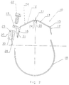
- the structure of the clamping device is shown in detail in Figures 2 and 3.
- the clamping device consists of a stable, flexible upper part 10, which is adapted to the surface contour of the saddle fitting 3 of the tapping saddle 1.
- the upper part 10 has a narrow, flattened section 11 in the center, which is connected to a shoulder part 12, 13 on the right and left side. At the downward ends of the shoulder parts 12, 13 each have a film hinge 14, 15 extension parts 16, 17 formed.
- the right extension part 17 is simultaneously formed as a connecting tab, which consists of two sections 17 'and 17'', to which one end of the tension band 18 is welded.
- the left extension part 16 has a web 19 which is formed at a right angle and in which two elongated holes 20, 21 which are open on one side each hold a clamping screw 22 are arranged.
- two semicircular ribs 23 are arranged in the region of the hole edges.
- the two movable extension parts 16, 17 protrude beyond the saddle fitting 3 and, depending on the outer diameter, can be in contact with the main pipe 2.
- the upper part 10 is provided in the center with a cutout 26 which is open on the right-hand side.
- the extension part 17 consists of two sections 17 'and 17''. The recess 26 is required so that the upper part 10 can be placed on the saddle fitting 3 of the tapping saddle 1. If the pipe fitting only has a vertical pipe socket without a branch, only a circular recess is required to place the upper part on the saddle fitting.
- the tensioning device also includes a stable tensioning beam 27, the lower end of which is designed as a connecting tab 28 which is welded to the other end of the tensioning band 18.
- the clamping beam 27 has a stop 29 molded onto the upper side.
- Two sleeves 30, which run parallel to the main pipe tangent, are arranged on the tensioning beam 27 and serve as a connecting or fastening element for the tensioning screws 22.
- the clamping screws 22 are designed as self-tapping screws, so that a separate thread insert is not required.
- two reinforcing ribs 31 are arranged on the extension part 16 of the upper part 10, which serve as a guide for the two sleeves 30 at the same time.
- the clamping beam 27 and the upper part 10 of the clamping device consist of plastic and are produced as an injection molded part.
- the tensioning strap 18 consists of a material with a high tensile strength and a high elastic elongation, for example made of polyethylene.
- 1 shows the tensioning device in the fully assembled state of a tapping saddle 1 on a main pipe 2.
- the clamping device and the tapping saddle form a prefabricated structural unit, in which the two clamping screws 22 are already screwed into the sleeves 30 of the clamping beam 27.
- the free end of the tensioning band 18 with the tensioning bar 27 is placed around the main tube 2 and the tensioning screws 22 protruding from the tensioning bar are inserted into the elongated holes 20, 21 of the web 19 of the left extension part 16 and by briefly pulling the strap 18 down the screw heads are locked due to the semicircular ribs 23 and can no longer slip sideways.
- the fitter only needs to tighten the two tensioning screws 22 by means of a screwdriver to the block position of the stop 29 and the web 19, the tensioning band being stretched elastically. During the tightening of the screws, a targeted application of force takes place via the central web 9 in order to achieve the required contact pressure for the subsequent welding of the tapping saddle.
- the tensioning device effects an elastic re-tensioning during the welding process.
- the contact force between the main pipe 2 and the saddle fitting 3 is determined before and during the saddle welding by the circumferential force introduced to elongate the tension band 18 via the tension screws 22, which depends on the material cross section and the material strength of the tension band 18.
- the tensioning strap 18 has a width which corresponds to the length of the saddle fitting 3 of the tapping saddle, the distance between the two end faces of the saddle fitting 3 being determined as the length, and the thickness of the tensioning strap 18 is dimensioned accordingly so that the force conditions for the welding valve type and for the main pipe size.
- the cutting length of the tensioning band 18 is selected in accordance with the main tube size so that on the one hand the diameter tolerance of the main tube 2 is compensated and on the other hand the support conditions between the main tube 2 and the saddle fitting 3 are ensured before and during the saddle welding.
Landscapes
- Engineering & Computer Science (AREA)
- General Engineering & Computer Science (AREA)
- Mechanical Engineering (AREA)
- Lining Or Joining Of Plastics Or The Like (AREA)
- Clamps And Clips (AREA)
Applications Claiming Priority (2)
| Application Number | Priority Date | Filing Date | Title |
|---|---|---|---|
| DE29600182U DE29600182U1 (de) | 1996-01-09 | 1996-01-09 | Spannvorrichtung für Rohrarmaturen |
| DE29600182U | 1996-01-09 |
Publications (3)
| Publication Number | Publication Date |
|---|---|
| EP0789178A2 true EP0789178A2 (fr) | 1997-08-13 |
| EP0789178A3 EP0789178A3 (fr) | 1998-01-07 |
| EP0789178B1 EP0789178B1 (fr) | 1999-12-22 |
Family
ID=8017746
Family Applications (1)
| Application Number | Title | Priority Date | Filing Date |
|---|---|---|---|
| EP97100168A Expired - Lifetime EP0789178B1 (fr) | 1996-01-09 | 1997-01-08 | Dispositif de serrage pour appareils de robinetterie pour tuyaux |
Country Status (2)
| Country | Link |
|---|---|
| EP (1) | EP0789178B1 (fr) |
| DE (3) | DE29600182U1 (fr) |
Families Citing this family (1)
| Publication number | Priority date | Publication date | Assignee | Title |
|---|---|---|---|---|
| CN104191115B (zh) * | 2014-08-13 | 2016-04-20 | 浙江大学 | 一种新型马鞍形管件及其电熔焊接时的连接固定方法 |
Family Cites Families (11)
| Publication number | Priority date | Publication date | Assignee | Title |
|---|---|---|---|---|
| LU38542A1 (fr) * | 1959-07-17 | |||
| US3241800A (en) * | 1963-12-11 | 1966-03-22 | Gen Plastics Corp | Mounting device |
| US3779272A (en) * | 1970-05-18 | 1973-12-18 | Johns Manville | Pipe saddle assembly |
| CH528697A (de) * | 1972-02-08 | 1972-09-30 | Rollmaplast Ag Kunststoffrohr | Elektrisch schweissbares Anbohrformstück aus thermoplastischem Werkstoff |
| NL181415C (nl) * | 1975-02-21 | 1987-08-17 | Draka Polva Bv | Werkwijze en inrichting voor het vervaardigen van een kunststofonderdeel met een weerstandselement. |
| GB1544441A (en) * | 1976-02-18 | 1979-04-19 | Polva Nederland Bv | Method of and device for manufacturing a component of synthetic material and a resistance element |
| FR2519578A1 (fr) * | 1981-07-01 | 1983-07-18 | Sam Innovation Tech | Dispositif en matiere plastique pour realiser une perforation dans un element sous-jacent en matiere plastique, procede de fabrication d'un tel dispositif et sa mise en oeuvre pour realiser des derivations de canalisations |
| MC1468A1 (fr) * | 1982-03-10 | 1983-06-17 | Innotec | Prise de derivation electrosoudable pour les canalisations plastiques |
| DE8615854U1 (de) * | 1986-06-12 | 1986-11-06 | Jeschke, Immanuel, 3203 Sarstedt | Anbohrgerät für die Anbringung an einem ein flüssiges oder gasförmiges Medium führendes Rohr |
| US5360241A (en) * | 1991-08-07 | 1994-11-01 | Npc, Inc. | Universal saddle tee for pipes |
| DE9204079U1 (de) * | 1992-03-25 | 1992-05-21 | Manibs Spezialarmaturen GmbH & Co KG, 5630 Remscheid | Anbohrschelle aus Kunststoff mit einer Bohrbüchse |
-
1996
- 1996-01-09 DE DE29600182U patent/DE29600182U1/de not_active Expired - Lifetime
-
1997
- 1997-01-06 DE DE19700870A patent/DE19700870A1/de not_active Withdrawn
- 1997-01-08 DE DE59700864T patent/DE59700864D1/de not_active Expired - Fee Related
- 1997-01-08 EP EP97100168A patent/EP0789178B1/fr not_active Expired - Lifetime
Also Published As
| Publication number | Publication date |
|---|---|
| DE19700870A1 (de) | 1997-07-10 |
| DE59700864D1 (de) | 2000-01-27 |
| DE29600182U1 (de) | 1996-07-18 |
| EP0789178A3 (fr) | 1998-01-07 |
| EP0789178B1 (fr) | 1999-12-22 |
Similar Documents
| Publication | Publication Date | Title |
|---|---|---|
| DE3501679C1 (de) | Auslaufarmatur | |
| DE3781891T2 (de) | Bandschelle mit uebergrossen spannschraubenloechern. | |
| DE102007011194B3 (de) | Befestigungsclip zur Befestigung von Rohren | |
| EP0550813A1 (fr) | Raccord de tuyaux | |
| DE2541980C3 (de) | Rohrschelle | |
| EP0115246A1 (fr) | Collier de serrage | |
| CH708163B1 (de) | Spann- oder Rohrschelle. | |
| CH685403A5 (de) | Formteil aus thermoplastischem Material. | |
| DE10315690A1 (de) | Befestigungsvorrichtung für eine Anhängevorrichtung an einem Längsträger eines Kraftfahrzeuges | |
| DE10236550B4 (de) | Haltevorrichtung für ein Leitungsstrang-Schuhelement | |
| EP0787909B1 (fr) | Dispositif de fixation pour profilés assemblés de façon télescopique | |
| EP0789178B1 (fr) | Dispositif de serrage pour appareils de robinetterie pour tuyaux | |
| EP0525481A1 (fr) | Dispositif de maintien pour des tuyaux, en particulier pour tel dans des centrales | |
| DE19750251A1 (de) | Kettenförmige Rohrschelle | |
| CH669438A5 (en) | Clip and anchoring part | |
| DE69303038T2 (de) | Rohrschelle | |
| EP0226654A1 (fr) | Connecteur pour tubes et pour profilés creux tubulaires | |
| DE19903972A1 (de) | Mutter zur Schnellbefestigung | |
| DE3905175C1 (en) | Pipe clamp for hydraulic pipes | |
| EP0189052A1 (fr) | Dispositif de soudage pour conduit tubulaire | |
| DE3415294A1 (de) | Einteilige rohrschelle aus bandmaterial | |
| EP1956251A1 (fr) | Raccord d'angle amovible pour tubes, element d'angle destine au raccord d'angle amovible pour tubes et douille d'ecartement destinee au raccord d'angle amovible pour tubes | |
| DE102007025191A1 (de) | Rohrschelle | |
| EP0182238A1 (fr) | Bride pour tuyaux | |
| EP1528310B1 (fr) | Collier de serrage soudable avec fixation de transport pour dispositif de fixation |
Legal Events
| Date | Code | Title | Description |
|---|---|---|---|
| PUAI | Public reference made under article 153(3) epc to a published international application that has entered the european phase |
Free format text: ORIGINAL CODE: 0009012 |
|
| AK | Designated contracting states |
Kind code of ref document: A2 Designated state(s): CH DE GB LI |
|
| PUAL | Search report despatched |
Free format text: ORIGINAL CODE: 0009013 |
|
| AK | Designated contracting states |
Kind code of ref document: A3 Designated state(s): CH DE GB LI |
|
| 17P | Request for examination filed |
Effective date: 19980325 |
|
| 17Q | First examination report despatched |
Effective date: 19980923 |
|
| GRAG | Despatch of communication of intention to grant |
Free format text: ORIGINAL CODE: EPIDOS AGRA |
|
| GRAG | Despatch of communication of intention to grant |
Free format text: ORIGINAL CODE: EPIDOS AGRA |
|
| GRAH | Despatch of communication of intention to grant a patent |
Free format text: ORIGINAL CODE: EPIDOS IGRA |
|
| GRAH | Despatch of communication of intention to grant a patent |
Free format text: ORIGINAL CODE: EPIDOS IGRA |
|
| GRAA | (expected) grant |
Free format text: ORIGINAL CODE: 0009210 |
|
| RAP1 | Party data changed (applicant data changed or rights of an application transferred) |
Owner name: DA-KUNSTSTOFF GMBH |
|
| AK | Designated contracting states |
Kind code of ref document: B1 Designated state(s): CH DE GB LI |
|
| REG | Reference to a national code |
Ref country code: CH Ref legal event code: EP |
|
| REF | Corresponds to: |
Ref document number: 59700864 Country of ref document: DE Date of ref document: 20000127 |
|
| GBT | Gb: translation of ep patent filed (gb section 77(6)(a)/1977) |
Effective date: 20000202 |
|
| REG | Reference to a national code |
Ref country code: CH Ref legal event code: NV Representative=s name: SCHMAUDER & PARTNER AG PATENTANWALTSBUERO |
|
| PLBE | No opposition filed within time limit |
Free format text: ORIGINAL CODE: 0009261 |
|
| STAA | Information on the status of an ep patent application or granted ep patent |
Free format text: STATUS: NO OPPOSITION FILED WITHIN TIME LIMIT |
|
| 26N | No opposition filed | ||
| REG | Reference to a national code |
Ref country code: GB Ref legal event code: IF02 |
|
| PGFP | Annual fee paid to national office [announced via postgrant information from national office to epo] |
Ref country code: GB Payment date: 20031215 Year of fee payment: 8 |
|
| PGFP | Annual fee paid to national office [announced via postgrant information from national office to epo] |
Ref country code: CH Payment date: 20040129 Year of fee payment: 8 |
|
| PGFP | Annual fee paid to national office [announced via postgrant information from national office to epo] |
Ref country code: DE Payment date: 20040310 Year of fee payment: 8 |
|
| PG25 | Lapsed in a contracting state [announced via postgrant information from national office to epo] |
Ref country code: GB Free format text: LAPSE BECAUSE OF NON-PAYMENT OF DUE FEES Effective date: 20050108 |
|
| PG25 | Lapsed in a contracting state [announced via postgrant information from national office to epo] |
Ref country code: LI Free format text: LAPSE BECAUSE OF NON-PAYMENT OF DUE FEES Effective date: 20050131 Ref country code: CH Free format text: LAPSE BECAUSE OF NON-PAYMENT OF DUE FEES Effective date: 20050131 |
|
| PG25 | Lapsed in a contracting state [announced via postgrant information from national office to epo] |
Ref country code: DE Free format text: LAPSE BECAUSE OF NON-PAYMENT OF DUE FEES Effective date: 20050802 |
|
| GBPC | Gb: european patent ceased through non-payment of renewal fee |
Effective date: 20050108 |
|
| REG | Reference to a national code |
Ref country code: CH Ref legal event code: PL |