EP0789184A2 - Langgestreckte Signalleuchte für Fahrzeuge - Google Patents
Langgestreckte Signalleuchte für Fahrzeuge Download PDFInfo
- Publication number
- EP0789184A2 EP0789184A2 EP97101417A EP97101417A EP0789184A2 EP 0789184 A2 EP0789184 A2 EP 0789184A2 EP 97101417 A EP97101417 A EP 97101417A EP 97101417 A EP97101417 A EP 97101417A EP 0789184 A2 EP0789184 A2 EP 0789184A2
- Authority
- EP
- European Patent Office
- Prior art keywords
- carrier plate
- plate
- signal light
- long side
- connecting elements
- Prior art date
- Legal status (The legal status is an assumption and is not a legal conclusion. Google has not performed a legal analysis and makes no representation as to the accuracy of the status listed.)
- Granted
Links
- 230000003287 optical effect Effects 0.000 claims description 49
- 125000006850 spacer group Chemical group 0.000 claims description 19
- 238000003780 insertion Methods 0.000 claims description 14
- 230000037431 insertion Effects 0.000 claims description 14
- 238000007789 sealing Methods 0.000 abstract 1
- 239000012780 transparent material Substances 0.000 abstract 1
- 238000004519 manufacturing process Methods 0.000 description 2
- 238000000149 argon plasma sintering Methods 0.000 description 1
Images


Classifications
-
- B—PERFORMING OPERATIONS; TRANSPORTING
- B60—VEHICLES IN GENERAL
- B60Q—ARRANGEMENT OF SIGNALLING OR LIGHTING DEVICES, THE MOUNTING OR SUPPORTING THEREOF OR CIRCUITS THEREFOR, FOR VEHICLES IN GENERAL
- B60Q1/00—Arrangement of optical signalling or lighting devices, the mounting or supporting thereof or circuits therefor
- B60Q1/26—Arrangement of optical signalling or lighting devices, the mounting or supporting thereof or circuits therefor the devices being primarily intended to indicate the vehicle, or parts thereof, or to give signals, to other traffic
- B60Q1/30—Arrangement of optical signalling or lighting devices, the mounting or supporting thereof or circuits therefor the devices being primarily intended to indicate the vehicle, or parts thereof, or to give signals, to other traffic for indicating rear of vehicle, e.g. by means of reflecting surfaces
- B60Q1/302—Arrangement of optical signalling or lighting devices, the mounting or supporting thereof or circuits therefor the devices being primarily intended to indicate the vehicle, or parts thereof, or to give signals, to other traffic for indicating rear of vehicle, e.g. by means of reflecting surfaces mounted in the vicinity, e.g. in the middle, of a rear window
-
- B—PERFORMING OPERATIONS; TRANSPORTING
- B60—VEHICLES IN GENERAL
- B60Q—ARRANGEMENT OF SIGNALLING OR LIGHTING DEVICES, THE MOUNTING OR SUPPORTING THEREOF OR CIRCUITS THEREFOR, FOR VEHICLES IN GENERAL
- B60Q1/00—Arrangement of optical signalling or lighting devices, the mounting or supporting thereof or circuits therefor
- B60Q1/26—Arrangement of optical signalling or lighting devices, the mounting or supporting thereof or circuits therefor the devices being primarily intended to indicate the vehicle, or parts thereof, or to give signals, to other traffic
- B60Q1/2696—Mounting of devices using LEDs
-
- F—MECHANICAL ENGINEERING; LIGHTING; HEATING; WEAPONS; BLASTING
- F21—LIGHTING
- F21S—NON-PORTABLE LIGHTING DEVICES; SYSTEMS THEREOF; VEHICLE LIGHTING DEVICES SPECIALLY ADAPTED FOR VEHICLE EXTERIORS
- F21S43/00—Signalling devices specially adapted for vehicle exteriors, e.g. brake lamps, direction indicator lights or reversing lights
- F21S43/10—Signalling devices specially adapted for vehicle exteriors, e.g. brake lamps, direction indicator lights or reversing lights characterised by the light source
- F21S43/13—Signalling devices specially adapted for vehicle exteriors, e.g. brake lamps, direction indicator lights or reversing lights characterised by the light source characterised by the type of light source
- F21S43/14—Light emitting diodes [LED]
-
- F—MECHANICAL ENGINEERING; LIGHTING; HEATING; WEAPONS; BLASTING
- F21—LIGHTING
- F21S—NON-PORTABLE LIGHTING DEVICES; SYSTEMS THEREOF; VEHICLE LIGHTING DEVICES SPECIALLY ADAPTED FOR VEHICLE EXTERIORS
- F21S43/00—Signalling devices specially adapted for vehicle exteriors, e.g. brake lamps, direction indicator lights or reversing lights
- F21S43/10—Signalling devices specially adapted for vehicle exteriors, e.g. brake lamps, direction indicator lights or reversing lights characterised by the light source
- F21S43/13—Signalling devices specially adapted for vehicle exteriors, e.g. brake lamps, direction indicator lights or reversing lights characterised by the light source characterised by the type of light source
- F21S43/15—Strips of light sources
-
- F—MECHANICAL ENGINEERING; LIGHTING; HEATING; WEAPONS; BLASTING
- F21—LIGHTING
- F21S—NON-PORTABLE LIGHTING DEVICES; SYSTEMS THEREOF; VEHICLE LIGHTING DEVICES SPECIALLY ADAPTED FOR VEHICLE EXTERIORS
- F21S43/00—Signalling devices specially adapted for vehicle exteriors, e.g. brake lamps, direction indicator lights or reversing lights
- F21S43/10—Signalling devices specially adapted for vehicle exteriors, e.g. brake lamps, direction indicator lights or reversing lights characterised by the light source
- F21S43/19—Attachment of light sources or lamp holders
- F21S43/195—Details of lamp holders, terminals or connectors
-
- F—MECHANICAL ENGINEERING; LIGHTING; HEATING; WEAPONS; BLASTING
- F21—LIGHTING
- F21S—NON-PORTABLE LIGHTING DEVICES; SYSTEMS THEREOF; VEHICLE LIGHTING DEVICES SPECIALLY ADAPTED FOR VEHICLE EXTERIORS
- F21S43/00—Signalling devices specially adapted for vehicle exteriors, e.g. brake lamps, direction indicator lights or reversing lights
- F21S43/50—Signalling devices specially adapted for vehicle exteriors, e.g. brake lamps, direction indicator lights or reversing lights characterised by aesthetic components not otherwise provided for, e.g. decorative trim, partition walls or covers
- F21S43/51—Attachment thereof
Definitions
- the invention relates to an elongated signal lamp for vehicles with a light bar, consisting of a translucent lens of a support plate for light sources and an optical disc arranged between the support plate and lens.
- the signal lamp for vehicles has become known from DE 42 17 512 C1.
- the signal lamp is an elongated light bar, which has a translucent cover lens, a support plate for light sources and an optical lens arranged between the light sources and the cover lens.
- a printed circuit board which is equipped with light-emitting diodes, serves as the carrier plate.
- On the narrow side surfaces of the optical disc connecting elements are formed, between which the carrier plate is inserted and with which the carrier plate is connected in a self-locking manner.
- the self-engaging connection between the carrier plate and the connecting elements of the optical disk must be free of play, since the optical disk must keep the carrier plate with its light sources free from rattling and the distance between the light sources of the optical disk must be very precise.
- This optical unit consisting of an optical disc and carrier plate, is placed on a lower side wall of the light bar.
- the lower side wall is made in one piece with the cover plate, while the upper side wall, which covers the optical unit, is a separate part welded to the cover plate and lower side wall.
- the optical unit is held between the lower and upper side walls by retaining lugs which are molded onto the long narrow side surfaces of the optical disk and which engage in openings in the lower and upper long side walls without play.
- the retaining lugs and retaining openings are cost-intensive to manufacture and time-consuming and complicated to assemble because of their play-free interlocking.
- the Light bar can no longer be dismantled and the upper side wall is an additional part, which is to be connected to the lens in a separate operation.
- the light bar is inserted into an elongated opening of the vehicle body and, with an edge section of the end plate projecting outwards, lies against the outer edge region of the elongated opening.
- the light bar is fixed to the vehicle body with fastening screws attached to its rear.
- the object of the invention is to design the signal light described in the preamble of claim 1 in such a way that the signal light can be assembled from as few and as simple and quick-to-assemble parts as possible, and yet a precise distance between the optical disk and the carrier plate having light sources is ensured.
- This object is achieved according to the invention in that a plurality of connecting elements are formed on the long side edges of the cover lens, between which the optical disc and the carrier plate are inserted, the carrier plate being locked in place with the connecting elements of the cover lens and the optical disc additionally having a side that faces between them End plate and carrier plate extending spacer.
- the light bar consists of only three assembled parts, namely the cover lens, the optical lens and the support plate of the light sources.
- the optical disc is inserted between the connecting elements of the cover plate and held after the locking of the carrier plate with the connecting elements between the cover plate and carrier plate. Therefore, the optical disc does not have to have any additional fastening elements towards the carrier plate. Nevertheless, the optical disk is always precisely spaced from the light sources of the carrier plate, since the optical disk lies on the side of the carrier plate facing the cover disk. The optical disc also contributes to the stiffening of the light bar, since it is a spacer extending between the lens and carrier plate. A rattle-free connection To get between the lens, the carrier plate and the lens, the lens just has to be clamped between the lens and the carrier plate. The light bar builds very flat when the optical disc between connecting elements of the lens adjoins facing side edge sections of the lens and carrier plate.
- the optical disk with spacer elements molded onto narrow side faces adjoins side edge sections of the end disk and / or carrier plate.
- connecting elements of the cover lens and spacer elements of the optical lens are aligned one behind the other on each long side of the light bar.
- the spacer elements and the connecting elements therefore do not have to protrude into the areas of the cover lens and optical lens that are effective in terms of lighting technology.
- the flat light bar can be integrated in very flat rear spoilers or in flat housings, which can be attached inside the vehicle behind the rear window.
- the self-locking connection between the connecting elements of the cover plate and the carrier plate is particularly simple if the connecting elements are provided with latching openings into which latching lugs attached to the long side edges of the carrier plate engage in a self-latching manner.
- the locking lugs can engage with play in the locking openings if the locking lugs are held by the optical disc serving as a spacer against the side of the locking openings directed towards the end plate. This ensures that the locking lugs snap into the locking openings quickly and that the locking lugs and the locking openings do not have to be tolerated very closely.
- the latching lugs and the connecting elements are arranged in clearances of the long side edges of the carrier plate and the connecting elements adjoin at least on one side of the latching openings with a stop surface on the long side edge section of the carrier plate directed towards the end plate.
- the carrier plate can be made as wide as the cover plate.
- the support plate does not have to be kept free of play between the stop surface and the latching opening of each connecting element, since the optical disk is a spacer for the cover disk and the support plate.
- the length of the optical disc is on the carrier plate fixed when it engages with a shoulder in a recess made in the middle of a long side edge of the carrier plate.
- tolerance deviations do not add up over the entire length of the lens, but only starting from its center to the two sides.
- the light bar is inserted into an elongated opening of a housing which has an upper and a lower long side wall, the inner sides of which extend in the direction of insertion of the light bar and at least one long side wall of which is elastic transversely to the direction of insertion and longitudinal extension of the light bar is flexible and clamps and holds the light bar between the upper and lower side wall.
- a housing which has an upper and a lower long side wall, the inner sides of which extend in the direction of insertion of the light bar and at least one long side wall of which is elastic transversely to the direction of insertion and longitudinal extension of the light bar is flexible and clamps and holds the light bar between the upper and lower side wall.
- the housing can have a smooth surface on the outside of the upper and lower side walls.
- the light bar is very securely fixed in the housing if the housing has locking cams formed at least on the inside of a long side wall.
- the locking cams are particularly advantageous if they taper towards its free end and have a sliding surface directed in and against the direction of insertion of the optical disk.
- the sliding surface directed in the direction of insertion enables the housing to be demolded, and the sliding surface directed in the opposite direction serves to make it easier for the light strip to be pressed into the housing.
- the signal lamp for vehicles is arranged inside the vehicle behind the upper edge region of a rear window (15) and is attached to the body (28) adjacent to the rear window (15). Seen from the front of the signal light, the signal light is very flat and is elongated in the horizontal. As a result, the signal light covers only a small area of the rear window (15) from the inside of the vehicle and does not appear to be a distracting part for the driver when looking into the rear view mirror.
- the headliner (29) is adjacent to the rear floor (16) of the signal lamp.
- the headlining (29) can also cover the entire signal lamp and be connected to the signal lamp near the rear window (15).
- the signal lamp is arranged near a seal between the rear window (15) and the body (28) and is fastened to the body (28) by means of fastening tabs (30) and fastening screws (31) on the body.
- the fastening screws (31) are guided with their threaded shafts through an opening in the fastening lugs (30) and engage in a thread of the body (28).
- the fastening tabs (30) are molded onto the bottom (16) of a housing (3) of the signal lamp. Starting from the bottom (16), the housing (3) has a long upper and lower side wall (4, 5) which, with the short side walls (32) connecting them, define an elongated opening (2) in the housing (3).
- the side walls (4, 5 and 32) extend with their free edge close to the rear window (15). So that no light reflected on the rear window can disruptively illuminate the vehicle interior.
- a light bar (1) is inserted into the elongated opening (2) in the direction of insertion (6).
- the side walls (4, 5 and 32) run, as do their inner sides (7) in the direction of insertion (6) of the light bar (1).
- the light bar (1) is composed of a cover plate (11), a carrier plate (13) for light sources (14) and an optical plate (19) arranged between the light sources (14) and the cover plate (11).
- a circuit board serves as the carrier plate (13) and light-emitting diodes soldered to the circuit board serve as light sources (14).
- Tab-like connecting elements (12) are formed on the long side edges of the end plate (11), between which the elongated optical disc (19) and the elongated carrier plate (13) are inserted in the direction (34), the carrier plate (13) with latching lugs (25 ) automatically engage on their long sides in a latching opening (24) of the connecting elements (12) with great play.
- Spacer elements (23) are formed between the connecting elements (12) on the narrow side surfaces of the optical disk (19), which abuts the inner sides of the connecting elements (12). Some of the spacer elements (23) extend both to a side edge section (20) of the carrier plate (13) and to a side edge section (21) of the cover plate (11), while other spacer elements (23) extend exclusively to the side edge section (21) of the cover plate (11) and / or extend to the carrier plate (13).
- the spacer elements (23), which extend exclusively towards the carrier plate (13), are molded onto the short side edges of the optical disk (19).
- the optical disc (19) is clamped with its spacer elements (23) between the carrier plate (13) and the end plate (11) and thus presses the latching lugs (25) of the carrier plate (13) against the side of the latch openings directed towards the end plate (11) (24) of the connecting elements (12).
- the locking lugs (25) of the carrier plate (13) are arranged together with the connecting elements (12) in a clearing of the long side edges of the carrier plate (13), not shown.
- the connecting elements (12) have a stop surface (26) on both sides of their latching opening (24) which adjoins the side edge section (20) of the carrier plate (13).
- the optical disc (19) has a spacer element (23) with a shoulder (27) in the middle of a long side, which is shown in engages a not shown recess on the side edge of the support plate (13).
- a light-bundling optical element (33) of the optical disk (19) is assigned to each of the light sources (14) arranged side by side in a row. While the cover plate (11) is provided with light-scattering optical elements (not shown). Seen in the longitudinal extension of the light bar (1), connecting elements (12) and spacer elements (23) are aligned one behind the other on both long sides of the light bar (1). This makes it possible for the end plate (11) with the outside of their long side edges and their connecting elements (12) together with the outside of the spacer elements (23) to lie approximately in a surface extending in the direction of insertion (6).
- the upper and lower side wall (4, 5) of the housing (3) is designed to be resilient transversely to the direction of insertion (6) and the longitudinal extent of the light bar (1).
- Snap cams (8) are formed on the inner sides (7) at a distance from the floor (16), which have a sliding surface (9) directed in and against the direction of insertion (6).
- the locking cams (8) taper towards their free end through the sliding surfaces (9).
- stops (10) formed by projections are formed on the inside of the bottom (16) of the housing (3).
- the upper and lower side walls (5) spring together and are pretensioned on the outer sides of the connection elements (12) and the long side edges of the cover plate (11) and carrier plate (13), while the locking cams (8) adjoin the front of the cover plate (11).
- the light bar (1) is thus held free of play between the stops (10) and the locking cams (8) in the direction of insertion (6).
- a connector (18) is attached to the back of the carrier plate (13) and protrudes through an opening (17) made in the bottom (16) of the housing (3). So that the light bar (1) is not pressed towards the rear window (15) when a plug (not shown) is plugged onto the plug connection (18), the plug connection is locked in the opening (17).
Landscapes
- Engineering & Computer Science (AREA)
- General Engineering & Computer Science (AREA)
- Mechanical Engineering (AREA)
- Physics & Mathematics (AREA)
- Microelectronics & Electronic Packaging (AREA)
- Optics & Photonics (AREA)
- Non-Portable Lighting Devices Or Systems Thereof (AREA)
- Lighting Device Outwards From Vehicle And Optical Signal (AREA)
Abstract
Description
- Die Erfindung betrifft eine langgestreckte Signalleuchte für Fahrzeuge mit einer Lichtleiste, bestehend aus einer lichtdurchlässigen Abschlußscheibe einer Trägerplatte für Lichtquellen und einer zwischen Trägerplatte und Abschlußscheibe angeordneten Optikscheibe.
- Aus der DE 42 17 512 C1 ist eine solche Signalleuchte für Fahrzeuge bekanntgeworden. Die Signalleuchte ist eine langgestreckte Lichtleiste, welche eine lichtdurchlässige Abschlußscheibe, eine Trägerplatte für Lichtquellen und eine zwischen den Lichtquellen und Abschlußscheibe angeordnete Optikscheibe aufweist. Als Trägerplatte dient eine Leiterplatte, welche mit Leuchtdioden bestückt ist. An die schmalen Seitenflächen der Optikscheibe sind Verbindungselemente angeformt, zwischen welchen die Trägerplatte eingesetzt ist und mit welchen die Trägerplatte selbstrastend verbunden ist. Die selbstrastende Verbindung zwischen der Trägerplatte und den Verbindungselementen der Optikscheibe muß spielfrei sein, da die Optikscheibe die Trägerplatte mit ihren Lichtquellen klapperfrei halten muß und die Distanz zwischen den Lichtquellen der Optikscheibe sehr genau sein muß. Die Herstellung spielfreier Rastverbindungen ist wegen enger Toleranzen kostenintensiv und das Fügen der beiden Teile kann umständlich und zeitaufwendig sein. Diese aus Optikscheibe und Trägerplatte bestehende optische Einheit ist auf eine untere Seitenwand der Lichtleiste aufgelegt. Die untere Seitenwand ist einstückig mit der Abschlußscheibe ausgeführt, während die obere Seitenwand, welche die optische Einheit abdeckt, ein mit der Abschlußscheibe und unteren Seitenwand verschweißtes separates Teil ist. Die optische Einheit ist zwischen der unteren und oberen Seitenwand durch Haltenasen gehalten, welche an die langen schmalen Seitenflächen der Optikscheibe angeformt sind und spielfrei in Öffnungen der unteren und oberen langen Seitenwand eingreifen. Auch hierbei sind die Haltenasen und Halteöffnungen wegen ihrem spielfreien Ineinandergreifen kostenintensiv in der Herstellung und zeitaufwendig und umständlich zu montieren. Zudem ist die Lichtleiste nicht mehr demontierbar und die obere Seitenwand ist ein zusätzliches Teil, welches in einem gesonderten Arbeitsgang mit der Abschlußscheibe zu verbinden ist. Die Lichtleiste ist in eine langgestreckte Öffnung der Fahrzeugkarosserie eingesteckt und liegt mit einem nach außen abstehenden Randabschnitt der Abschlußscheibe an dem äußeren Randbereich der langgestreckten Öffnung an. An der Fahrzeugkarosserie ist die Lichtleiste mit an ihrer Rückseite angebrachten Befestigungsschrauben festgesetzt.
- Aus der DE 40 03 569 A1 ist eine Signalleuchte für Fahrzeuge bekanntgeworden, bei welcher eine Optikscheibe, welche zwischen den Lichtquellen einer Trägerplatte und seiner äußeren Abschlußscheibe angeordnet ist, mit der Abschlußscheibe verschweißt ist.
- Aufgabe der Erfindung ist es, die im Oberbegriff des Anspruchs 1 beschriebene Signalleuchte derart zu gestalten, daß die Signalleuchte aus möglichst wenigen und einfach und schnell zu montierenden Teilen zusammensetzbar ist und trotzdem ein genauer Abstand zwischen der Optikscheibe und der Lichtquellen aufweisenden Trägerplatte gewährleistet ist. Diese Aufgabe wird nach der Erfindung dadurch gelöst, daß an lange Seitenränder der Abschlußscheibe mehrere Verbindungselemente angeformt sind, zwischen welchen die Optikscheibe und die Trägerplatte eingesetzt ist, wobei die Trägerplatte mit den Verbindungselementen der Abschlußscheibe verrastet ist und die Optikscheibe zusätzlich ein zwischen sich zugewandten Seiten von Abschlußscheibe und Trägerplatte sich erstreckendes Distanzstück ist. Die Lichtleiste besteht aus nur drei zusammengesetzten Teilen, nämlich der Abschlußscheibe, der Optikscheibe und der Trägerplatte der Lichtquellen. Die Optikscheibe ist zwischen die Verbindungselemente der Abschlußscheibe eingesetzt und nach dem Verrasten der Trägerplatte mit den Verbindungselementen zwischen Abschlußscheibe und Trägerplatte gehalten. Deshalb muß die Optikscheibe keine zusätzlichen Befestigungselemente zur Trägerplatte hin aufweisen. Trotzdem ist die Optikscheibe immer genau zu den Lichtquellen der Trägerplatte beabstandet, da die Optikscheibe an der der Abschlußscheibe zugewandten Seite der Trägerplatte anliegt. Die Optikscheibe trägt auch zur Versteifung der Lichtleiste bei, da sie ein zwischen Abschlußscheibe und Trägerplatte sich erstreckendes Distanzstück ist. Um eine klapperfreie Verbindung zwischen Optikscheibe, Trägerplatte und Abschlußscheibe zu erhalten, muß lediglich die Optikscheibe zwischen Abschlußscheibe und Trägerplatte eingespannt sein. Die Lichtleiste baut sehr flach, wenn die Optikscheibe zwischen Verbindungselementen der Abschlußscheibe an sich zugewandten Seitenrandabschnitten von Abschlußscheibe und Trägerplatte angrenzt. Hierbei ist es zweckmäßig, wenn die Optikscheibe mit an schmale Seitenflächen angeformten Distanzelementen an Seitenrandabschnitte von Abschlußscheibe und/oder Trägerplatte angrenzt. Bei einer solchen Anordnung liegen in Längsausdehnung der Lichtleiste gesehen an jeder Längsseite der Lichtleiste Verbindungselemente der Abschlußscheibe und Distanzelemente der Optikscheibe fluchtend hintereinander. Die Distanzelemente und die Verbindungselemente müssen somit nicht in die lichttechnisch wirksamen Bereiche von Abschlußscheibe und Optikscheibe hineinragen. Die flache Lichtleiste kann in sehr flache Heckspoiler integriert werden oder in flache Gehäuse, welche im Fahrzeuginneren hinter der Heckscheibe anbringbar sind.
- Die selbstrastende Verbindung zwischen den Verbindungselementen der Abschlußscheibe und der Trägerplatte ist besonders einfach gestaltet, wenn die Verbindungselemente mit Rastöffnungen versehen sind, in welche an die langen Seitenränder der Trägerplatte angebrachte Rastnasen selbstrastend eingreifen. Die Rastnasen können mit Spiel in die Rastöffnungen eingreifen, wenn die Rastnasen durch die als Distanzstück dienende Optikscheibe gegen die zur Abschlußscheibe hin gerichtete Seite der Rastöffnungen gehalten sind. Dadurch ist ein schnelles Einrasten der Rastnasen in die Rastöffnungen sicher und die Rastnasen und die Rastöffnungen müssen nicht sehr eng toleriert werden.
- Weiterhin ist es vorteilhaft, wenn die Rastnasen und die Verbindungselemente in Freimachungen der langen Seitenränder der Trägerplatte angeordnet sind und die Verbindungselemente zumindest auf einer Seite der Rastöffnungen mit einer Anschlagfläche an den zur Abschlußscheibe hin gerichteten langen Seitenrandabschnitt der Trägerplatte angrenzt. Dadurch kann die Trägerplatte so breit wie die Abschlußscheibe ausgeführt sein. Die Trägerplatte muß zwischen der Anschlagfläche und der Rastöffnung jedes Verbindungselementes nicht spielfrei gehalten sein, da die Optikscheibe ein Distanzstück für Abschlußscheibe und Trägerplatte ist. Die Optikscheibe ist in ihrer Längsausdehnung an der Trägerplatte fixiert, wenn sie mit einem Ansatz in eine mittig eines langen Seitenrandes der Trägerplatte eingebrachte Aussparung eingreift. Zudem addieren sich Toleranzabweichungen nicht über die gesamte Länge der Optikscheibe, sondern nur ausgehend von ihrer Mitte zu den beiden Seiten hin.
- Bei einer besonders vorteilhaften Weiterbildung der Erfindung ist die Lichtleiste in eine langgestreckte Öffnung eines Gehäuses eingesetzt, welches eine obere und eine untere lange Seitenwand aufweist, deren Innenseiten in Einsetzrichtung der Lichtleiste verlaufen und von denen zumindest eine lange Seitenwand quer zur Einsetzrichtung und Längsausdehnung der Lichtleiste elastisch nachgiebig ausgeführt ist und die Lichtleiste zwischen der oberen und unteren Seitenwand einspannt und hält. Dadurch baut nicht nur die Lichtleiste sehr flach, sondern auch das die Lichtleiste aufnehmende Gehäuse. Zudem ist die Lichtleiste nach ihrem Einsetzen selbsttätig zwischen den langen Seitenwänden gehalten und zur Herstellung des Gehäuses sind keine zusätzlich verstellbaren Werkzeuge notwendig. Darüber hinaus kann das Gehäuse an der Außenseite der oberen und unteren Seitenwand eine glatte Oberfläche aufweisen.
- Die Lichtleiste ist sehr sicher in dem Gehäuse festgesetzt, wenn das Gehäuse zumindest an der Innenseite einer langen Seitenwand angeformte Rastnocken aufweist. Die Rastnocken sind besonders vorteilhaft gestaltet, wenn sie sich zu seinem freien Ende hin verjüngen und eine in und eine entgegen der Einsetzrichtung der Optikscheibe gerichtete Gleitfläche aufweisen. Durch die in Einsetzrichtung gerichtete Gleitfläche ist eine Zwangsentformung des Gehäuses möglich und die entgegen der Einsetzrichtung gerichtete Gleitfläche dient zum leichteren Eindrücken der Lichtleiste in das Gehäuse.
- Ein Ausführungsbeispiel nach der Erfindung ist in den Zeichnungen dargestellt, und zwar zeigen
- Figur 1
- in einer perspektivischen Ansicht eine langgestreckte Signalleuchte für Fahrzeuge, mit einer Lichtleiste, welche in ein Gehäuse eingesetzt ist;
- Figur 2
- eine Vorderansicht auf die Signalleuchte;
- Figur 3
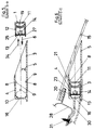
- einen Schnitt nach der Linie A-A in Figur 2 durch die Signalleuchte;
- Figur 4
- einen Schnitt nach der Linie B-B in Figur 2;
- Figur 5
- einen Schnitt nach der Linie B-B, mit dem Gehäuse und der Lichtleiste vor ihrem Zusammenfügen;
- Figur 6
- einen Schnitt nach der Linie C-C in Figur 2;
- Figur 7
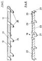
- eine perspektivische Darstellung einer äußeren Abschlußscheibe der Lichtleiste und
- Figur 8
- in einer perspektivischen Darstellung eine Optikscheibe, welche im Inneren der Lichtleiste angeordnet ist.
- Die Signalleuchte für Fahrzeuge ist im Fahrzeuginneren eines Fahrzeuges hinter dem oberen Randbereich einer Heckscheibe (15) angeordnet und ist an der an die Heckscheibe (15) angrenzenden Karosserie (28) befestigt. Von der Vorderseite der Signalleuchte her gesehen baut die Signalleuchte sehr flach und ist in der Horizontalen langgestreckt ausgeführt. Somit deckt die Signalleuchte vom Fahrzeuginneren her gesehen nur einen kleinen Bereich der Heckscheibe (15) ab und erscheint für den Fahrer beim Blick in den Rückspiegel nicht als ein störendes Teil. Der Dachhimmel (29) grenzt an den rückwärtigen Boden (16) der Signalleuchte an. Der Dachhimmel (29) kann auch die gesamte Signalleuchte abdecken und nahe der Heckscheibe (15) mit der Signalleuchte verbunden sein. Die Signalleuchte ist nahe einer Dichtung zwischen der Heckscheibe (15) und der Karosserie (28) angeordnet und ist an der Karosserie (28) mittels Befestigungslaschen (30) und Befestigungsschrauben (31) an der Karosserie befestigt. Die Befestigungsschrauben (31) sind mit ihrem Gewindeschaft durch eine Öffnung der Befestigungslaschen (30) hindurchgeführt und greifen in ein Gewinde der Karosserie (28) ein. Die Befestigungslaschen (30) sind an den Boden (16) eines Gehäuses (3) der Signalleuchte angeformt. Das Gehäuse (3) weist ausgehend vom Boden (16) eine lange obere und untere Seitenwand (4, 5) auf, welche mit sie verbindenden kurzen Seitenwänden (32) eine langgestreckte Öffnung (2) des Gehäuses (3) begrenzen.
- Die Seitenwände (4, 5 und 32) erstrecken sich mit ihrem freien Rand bis nahe an die Heckscheibe (15) heran. Damit kein an der Heckscheibe reflektiertes Licht den Fahrzeuginnenraum störend erhellen kann. In die langgestreckte Öffnung (2) ist eine Lichtleiste (1) in Einsetzrichtung (6) eingeschoben. Die Seitenwände (4, 5 und 32) verlaufen, wie auch ihre Innenseiten (7) in Einsetzrichtung (6) der Lichtleiste (1).
- Die Lichtleiste (1) ist aus einer Abschlußscheibe (11), einer Trägerplatte (13) für Lichtquellen (14) und einer zwischen den Lichtquellen (14) und der Abschlußscheibe (11) angeordneten Optikscheibe (19) zusammengesetzt. Als Trägerplatte (13) dient eine Leiterplatte und als Lichtquellen (14) mit der Leiterplatte verlötete Leuchtdioden. An die langen Seitenränder der Abschlußscheibe (11) sind laschenartige Verbindungselemente (12) angeformt, zwischen welchen die langgestreckte Optikscheibe (19) und die langgestreckte Trägerplatte (13) in Richtung (34) eingesetzt ist, wobei die Trägerplatte (13) mit Rastnasen (25) an ihren langen Seiten selbsttätig in jeweils eine Rastöffnung (24) der Verbindungselemente (12) mit großem Spiel eingreifen. An die schmalen Seitenflächen der Optikscheibe (19), welche an den Innenseiten der Verbindungselemente (12) anliegt, sind zwischen Verbindungselementen (12) Distanzelemente (23) angeformt. Einige der Distanzelemente (23) erstrecken sich sowohl zu einem Seitenrandabschnitt (20) der Trägerplatte (13) als auch zu einem Seitenrandabschnitt (21) der Abschlußscheibe (11) hin, während andere Distanzelemente (23) sich ausschließlich zum Seitenrandabschnitt (21) der Abschlußscheibe (11) und/oder zur Trägerplatte (13) hin erstrecken. Die sich ausschließlich zur Trägerplatte (13) hin erstreckenden Distanzelemente (23) sind an die kurzen Seitenränder der Optikscheibe (19) angeformt. Die Optikscheibe (19) ist mit ihren Distanzelementen (23) zwischen der Trägerplatte (13) und der Abschlußscheibe (11) eingespannt und drückt somit die Rastnasen (25) der Trägerplatte (13) gegen die zur Abschlußscheibe (11) hin gerichtete Seite der Rastöffnungen (24) der Verbindungselemente (12). Die Rastnasen (25) der Trägerplatte (13) sind zusammen mit den Verbindungselementen (12) in einer nicht dargestellten Freimachung der langen Seitenränder der Trägerplatte (13) angeordnet. Die Verbindungselemente (12) weisen auf beiden Seiten ihrer Rastöffnung (24) eine Anschlagfläche (26) auf, welche an den Seitenrandabschnitt (20) der Trägerplatte (13) angrenzt. Die Optikscheibe (19) weist mittig einer Längsseite ein Distanzelement (23) mit einem Ansatz (27) auf, welcher in eine nicht dargestellte Aussparung am Seitenrand der Trägerplatte (13) eingreift. Den in einer Reihe nebeneinander angeordneten Lichtquellen (14) ist jeweils ein das Licht bündelndes optisches Element (33) der Optikscheibe (19) zugeordnet. Während die Abschlußscheibe (11) mit das Licht streuenden optischen Elementen (nicht dargestellt) versehen ist. In Längsausdehnung der Lichtleiste (1) gesehen, liegen an beiden Längsseiten der Lichtleiste (1) Verbindungselemente (12) und Distanzelemente (23) fluchtend hintereinander. Dadurch ist es möglich, daß die Abschlußscheibe (11) mit der Außenseite ihrer langen Seitenränder und ihrer Verbindungselemente (12) zusammen mit der Außenseite der Distanzelemente (23) annähernd in einer in Einsetzrichtung (6) verlaufenden Fläche liegen.
- Die obere und untere Seitenwand (4, 5) des Gehäuses (3) ist quer zur Einsetzrichtung (6) und Längsausdehnung der Lichtleiste (1) elastisch nachgiebig ausgeführt. An den Innenseiten (7) sind in einem Abstand zum Boden (16) Rastnocken (8) angeformt, welche eine in und eine entgegen der Einsetzrichtung (6) gerichtete Gleitfläche (9) aufweisen. Durch die Gleitflächen (9) verjüngen sich die Rastnocken (8) zu ihrem freien Ende hin. An die Innenseite des Bodens (16) des Gehäuses (3) sind von Ansätzen gebildete Anschläge (10) angeformt. Beim Einschieben der Lichtleiste (1) in das Gehäuse (3) gleiten die Verbindungselemente (12) mit ihren freien Enden an Gleitflächen (9) der Rastnocken (8) entlang und drücken dabei die federnden Seitenwände (4, 5) auseinander. Nach einem Anschlagen der freien Enden der Verbindungselemente (12) der Abschlußscheibe (11) an die Anschläge (10) federn die obere und untere Seitenwand (5) zusammen und liegen unter Vorspannung an den Außenseiten der Verbindungselemente (12) und den langen Seitenrändern von Abschlußscheibe (11) und Trägerplatte (13) an, während die Rastnocken (8) an die Vorderseite der Abschlußscheibe (11) angrenzen. Somit ist die Lichtleiste (1) in Einsetzrichtung (6) spielfrei zwischen den Anschlägen (10) und den Rastnocken (8) gehalten. An der Rückseite der Trägerplatte (13) ist ein Steckeranschluß (18) befestigt, welcher durch einen in dem Boden (16) des Gehäuses (3) eingebrachten Durchbruch (17) hindurchragt. Damit beim Aufstecken eines Steckers (nicht dargestellt) auf den Steckeranschluß (18) die Lichtleiste (1) nicht zur Heckscheibe (15) hingedrückt wird, ist der Steckeranschluß selbstrastend in dem Durchbruch (17) festgesetzt.
-
- 1
- Lichtleiste
- 2
- langgestreckte Öffnung
- 3
- Gehäuse
- 4
- obere Seitenwand
- 5
- untere Seitenwand
- 6
- Einsetzrichtung
- 7
- Innenseiten
- 8
- Rastnocken
- 9
- Gleitfläche
- 10
- Anschlag
- 11
- Abschlußscheibe
- 12
- Verbindungselemente
- 13
- Trägerplatte
- 14
- Lichtquellen
- 15
- Heckscheibe
- 16
- Boden
- 17
- Durchbruch
- 18
- Steckeranschluß
- 19
- Optikscheibe
- 20
- Seitenrandabschnitte der Trägerplatte
- 21
- Seitenrandabschnitte der Abschlußscheibe
- 22
- schmale Seitenflächen der Optikscheibe
- 23
- Distanzelemente
- 24
- Rastöffnungen
- 25
- Rastnasen
- 26
- Anschlagfläche
- 27
- Ansatz
- 28
- Karosserie
- 29
- Dachhimmel
- 30
- Befestigungslaschen
- 31
- Befestigungsschrauben
- 32
- kurze Seitenwände
- 33
- optisches Element
Claims (10)
- Langgestreckte Signalleuchte für Fahrzeuge, mit einer Lichtleiste (1), bestehend aus einer lichtdurchlässigen Abschlußscheibe (11), einer Trägerplatte (13) für Lichtquellen (14) und einer zwischen Trägerplatte (13) und Abschlußscheibe (11) angeordneten Optikscheibe (19), dadurch gekennzeichnet, daß an lange Seitenränder der Abschlußscheibe (11) mehrere Verbindungselemente (12) angeformt sind, zwischen welchen die Optikscheibe (19) und die Trägerplatte (13) eingesetzt ist, wobei die Trägerplatte (13) mit den Verbindungselementen (12) der Abschlußscheibe (11) verrastet ist und die Optikscheibe (19) zusätzlich ein zwischen sich zugewandten Seiten von Abschlußscheibe (11) und Trägerplatte (13) sich erstreckendes Distanzstück ist.
- Signalleuchte nach Anspruch 1, dadurch gekennzeichnet, daß die Optikscheibe (19) zwischen Verbindungselementen (12) an sich zugewandten Seitenrandabschnitten (20 und 21) von Abschlußscheibe (11) und Trägerplatte (13) angrenzt.
- Signalleuchte nach Anspruch 1 oder 2, dadurch gekennzeichnet, daß die Optikscheibe (19) mit an schmale Seitenflächen (22) angeformten Distanzelementen (23) an Seitenrandabschnitte (20, 21) von Abschlußscheibe (12) und/oder Trägerplatte (13) angrenzt.
- Signalleuchte nach einem der Ansprüche 1 bis 3, dadurch gekennzeichnet, daß die Verbindungselemente (12) der Abschlußscheibe (11) mit Rastöffnungen (24) versehen sind, in welche an die langen Seitenränder der Trägerplatte (13) angebrachte Rastnasen (25) selbstrastend eingreifen.
- Signalleuchte nach Anspruch 4, dadurch gekennzeichnet, daß die Rastnasen (25) mit Spiel in die Rastöffnungen (24) eingreifen und durch die als Distanzstück dienende Optikscheibe (19) gegen die zur Abschlußscheibe (11) hin gerichtete Seite der Rastöffnungen (24) gehalten sind.
- Signalleuchte nach Anspruch 4 oder 5, dadurch gekennzeichnet, daß die Rastnasen (25) und die Verbindungselemente (12) in Freimachungen der langen Seitenränder der Trägerplatte (13) angeordnet sind und die Verbindungselemente (12) zumindest auf einer Seite der Rastöffnungen (24) mit einer Anschlagfläche (26) an den zur Abschlußscheibe (11) hin gerichteten langen Seitenrandabschnitt (20) der Trägerplatte (13) angrenzt.
- Signalleuchte nach Anspruch 3, dadurch gekennzeichnet, daß die Optikscheibe (19) mit einem Ansatz (27) in eine mittig eines langen Seitenrandes der Trägerplatte (13) eingebrachte Aussparung eingreift und die Optikscheibe (19) in ihrer Längsausdehnung an der Trägerplatte (13) festsetzt.
- Signalleuchte nach einem der Ansprüche 1 bis 7, dadurch gekennzeichnet, daß die Lichtleiste (1) in eine langgestreckte Öffnung (2) eines Gehäuses (3) eingesetzt ist, welches eine obere und untere lange Seitenwand (4, 5) aufweist, deren Innenseiten in Einsetzrichtung (6) der Lichtleiste (1) verlaufen und von denen zumindest eine lange Seitenwand (4 oder 5) quer zur Einsetzrichtung (6) und Längsausdehnung der Lichtleiste (1) elastisch nachgiebig ausgeführt ist und die Abschlußscheibe (11) zwischen der oberen und unteren Seitenwand (4, 5) einspannt und hält.
- Signalleuchte nach Anspruch 8, dadurch gekennzeichnet, daß das Gehäuse (3) zumindest an der Innenseite einer langen Seitenwand angeformte Rastnocken (8) aufweist, welche die Lichtleiste (1) selbsttätig in dem Gehäuse (3) festsetzen.
- Signalleuchte nach Anspruch 9, dadurch gekennzeichnet, daß die Rastnocken (8) sich zu ihrem freien Ende hin verjüngen und eine in und eine entgegen der Einsetzrichtung der Optikscheibe (19) gerichtete Gleitfläche (9) aufweisen.
Applications Claiming Priority (2)
| Application Number | Priority Date | Filing Date | Title |
|---|---|---|---|
| DE19604487A DE19604487C1 (de) | 1996-02-08 | 1996-02-08 | Langgestreckte Signalleuchte für Fahrzeuge |
| DE19604487 | 1996-02-08 |
Publications (3)
| Publication Number | Publication Date |
|---|---|
| EP0789184A2 true EP0789184A2 (de) | 1997-08-13 |
| EP0789184A3 EP0789184A3 (de) | 1999-03-24 |
| EP0789184B1 EP0789184B1 (de) | 2002-07-17 |
Family
ID=7784794
Family Applications (1)
| Application Number | Title | Priority Date | Filing Date |
|---|---|---|---|
| EP97101417A Expired - Lifetime EP0789184B1 (de) | 1996-02-08 | 1997-01-30 | Langgestreckte Signalleuchte für Fahrzeuge |
Country Status (3)
| Country | Link |
|---|---|
| EP (1) | EP0789184B1 (de) |
| DE (2) | DE19604487C1 (de) |
| ES (1) | ES2179226T3 (de) |
Cited By (4)
| Publication number | Priority date | Publication date | Assignee | Title |
|---|---|---|---|---|
| RU2398995C1 (ru) * | 2009-03-27 | 2010-09-10 | Учреждение Российской академии наук Институт проблем управления им. В.А. Трапезникова РАН | Светодиодный фонарь для транспортного средства |
| FR3081536A1 (fr) * | 2018-05-28 | 2019-11-29 | Psa Automobiles Sa | Bloc optique de vehicule automobile et vehicule automobile comportant un tel element. |
| WO2024079397A1 (fr) * | 2022-10-13 | 2024-04-18 | Stellantis Auto Sas | Assemblage de signalisation pour véhicule automobile à hayon |
| FR3153046A1 (fr) * | 2023-09-20 | 2025-03-21 | Psa Automobiles Sa | Support de fixation modulaire pour troisième feu stop de véhicule automobile |
Families Citing this family (11)
| Publication number | Priority date | Publication date | Assignee | Title |
|---|---|---|---|---|
| DE19714367A1 (de) * | 1997-02-06 | 1998-08-13 | Itt Mfg Enterprises Inc | Signalleuchte für ein Fahrzeug |
| DE19757927C1 (de) * | 1997-12-24 | 1999-04-08 | Hella Kg Hueck & Co | Signalleuchte für Fahrzeuge |
| DE19820360A1 (de) * | 1998-05-07 | 1999-11-11 | Hella Kg Hueck & Co | Rastbefestigung |
| DE19853878A1 (de) * | 1998-11-23 | 2000-07-20 | Hella Kg Hueck & Co | Langgestreckte Signalleuchte für Fahrzeuge |
| DE10217490B4 (de) * | 2002-04-19 | 2004-12-09 | Audi Ag | Kraftfahrzeug mit wenigstens einer Bremsleuchte in einem oberen Heckscheiben-Randbereich |
| DE102004031429B4 (de) * | 2003-07-01 | 2009-01-08 | Seat S.A. | Zusätzliche Bremslichtvorrichtung für Fahrzeuge |
| DE102005004051B4 (de) * | 2005-01-28 | 2007-04-05 | Johann & Konen Gmbh & Co. Kg | Abdeckelement für eine Leuchte und zugehörige Leuchte |
| DE102005004050B4 (de) * | 2005-01-28 | 2007-04-05 | Johann & Konen Gmbh & Co. Kg | Leuchte mit in der Leuchtenhaube integrierter Befestigung sowie deren Verwendung |
| DE102006002322B4 (de) * | 2006-01-18 | 2018-10-04 | HELLA GmbH & Co. KGaA | Leuchteinheit für Fahrzeuge mit einem Haltemodul zur rastenden Verbindung von Lichtleitelementen, einem Trägermodul und einer Seitenwand |
| FR3074561B1 (fr) * | 2017-12-01 | 2020-11-20 | Valeo Vision Belgique | Dispositif d'eclairage et/ou de signalisation de vehicule automobile |
| DE102020004412A1 (de) | 2020-07-22 | 2022-01-27 | Knorr-Bremse Gesellschaft Mit Beschränkter Haftung | Lichtleisteneinrichtung für einen Türflügel eines Einstiegssystems eines Schienenfahrzeugs |
Citations (2)
| Publication number | Priority date | Publication date | Assignee | Title |
|---|---|---|---|---|
| DE4003569A1 (de) | 1989-02-06 | 1990-08-09 | Koito Mfg Co Ltd | Kraftfahrzeugleuchte |
| DE4217512C1 (de) | 1992-05-27 | 1993-06-09 | Hella Kg Hueck & Co, 4780 Lippstadt, De |
Family Cites Families (3)
| Publication number | Priority date | Publication date | Assignee | Title |
|---|---|---|---|---|
| DE4026945C2 (de) * | 1990-08-25 | 1993-12-09 | Porsche Ag | Heckleuchte für ein Kraftfahrzeug |
| FR2697484B1 (fr) * | 1992-11-02 | 1995-01-20 | Valeo Vision | Elément modulaire pour la réalisation de feux de signalisation de véhicules automobiles. |
| FR2711216B1 (fr) * | 1993-10-14 | 1996-01-05 | Valeo Vision | Feu de signalisation à plusieurs sources de faible puissance et à moyens perfectionnés de traitement optique. |
-
1996
- 1996-02-08 DE DE19604487A patent/DE19604487C1/de not_active Expired - Fee Related
-
1997
- 1997-01-30 DE DE59707697T patent/DE59707697D1/de not_active Expired - Lifetime
- 1997-01-30 EP EP97101417A patent/EP0789184B1/de not_active Expired - Lifetime
- 1997-01-30 ES ES97101417T patent/ES2179226T3/es not_active Expired - Lifetime
Patent Citations (2)
| Publication number | Priority date | Publication date | Assignee | Title |
|---|---|---|---|---|
| DE4003569A1 (de) | 1989-02-06 | 1990-08-09 | Koito Mfg Co Ltd | Kraftfahrzeugleuchte |
| DE4217512C1 (de) | 1992-05-27 | 1993-06-09 | Hella Kg Hueck & Co, 4780 Lippstadt, De |
Cited By (5)
| Publication number | Priority date | Publication date | Assignee | Title |
|---|---|---|---|---|
| RU2398995C1 (ru) * | 2009-03-27 | 2010-09-10 | Учреждение Российской академии наук Институт проблем управления им. В.А. Трапезникова РАН | Светодиодный фонарь для транспортного средства |
| FR3081536A1 (fr) * | 2018-05-28 | 2019-11-29 | Psa Automobiles Sa | Bloc optique de vehicule automobile et vehicule automobile comportant un tel element. |
| WO2024079397A1 (fr) * | 2022-10-13 | 2024-04-18 | Stellantis Auto Sas | Assemblage de signalisation pour véhicule automobile à hayon |
| FR3140825A1 (fr) * | 2022-10-13 | 2024-04-19 | Psa Automobiles Sa | Assemblage de signalisation pour véhicule automobile à hayon |
| FR3153046A1 (fr) * | 2023-09-20 | 2025-03-21 | Psa Automobiles Sa | Support de fixation modulaire pour troisième feu stop de véhicule automobile |
Also Published As
| Publication number | Publication date |
|---|---|
| ES2179226T3 (es) | 2003-01-16 |
| DE59707697D1 (de) | 2002-08-22 |
| EP0789184A3 (de) | 1999-03-24 |
| DE19604487C1 (de) | 1997-04-03 |
| EP0789184B1 (de) | 2002-07-17 |
Similar Documents
| Publication | Publication Date | Title |
|---|---|---|
| EP0789184B1 (de) | Langgestreckte Signalleuchte für Fahrzeuge | |
| DE102006041734B4 (de) | Vorrichtung zur Befestigung einer Airbageinheit in einer Baugruppe eines Kraftfahrzeugs, insbesondere in einem Lenkrad, durch Verrasten | |
| DE3538361C1 (de) | Zusatzbremsleuchte fuer Kraftfahrzeuge | |
| DE9420291U1 (de) | Gehäuse aus zumindest zwei mittels einer Nut-Feder-Verbindung zusammensetzbaren Gehäuseteilen | |
| DE3426711A1 (de) | Scheinwerfer fuer fahrzeuge, insbesondere fuer kraftfahrzeuge | |
| DE29814233U1 (de) | Luftsackmodul | |
| EP0969985B1 (de) | Leuchte für fahrzeuge, insbesondere heckleuchte für fahrzeuge | |
| DE19722005A1 (de) | Beleuchtungseinrichtung für Fahrzeuge | |
| DE19835287A1 (de) | Gehäuse einer Heizungs- oder Klimaanlage eines Kraftfahrzeuges | |
| DE69400548T2 (de) | Zusatzwarnleuchte für Fahrzeuge | |
| DE19704067A1 (de) | Beleuchtungseinrichtung für Fahrzeuge | |
| DE29602125U1 (de) | Signalleuchte für Fahrzeuge | |
| DE69824984T2 (de) | Schutzgehäuse für eine Leiterplatte | |
| DE4438491C1 (de) | Leuchte für Fahrzeuge | |
| EP0413888B1 (de) | Anzeigeeinrichtung | |
| DE19822059A1 (de) | Vorrichtung zum Aufnehmen und Halten einer Batterie | |
| DE10327180A1 (de) | Außenrückblickspiegel für Fahrzeuge, vorzugsweise für Kraftfahrzeuge | |
| DE4238285C2 (de) | Scheinwerfer-Leuchten-Einheit für Fahrzeuge | |
| EP0669224B1 (de) | Leuchte für den Innenraum von Kraftfahrzeugen | |
| EP0829189B1 (de) | Universelle, modulare führungsschiene für leiterplatten | |
| DE19834390C1 (de) | Luftführungsgehäuse | |
| DE3633626C2 (de) | ||
| DE19809414A1 (de) | Zusatzbremsleuchte für ein Kraftfahrzeug | |
| DE102023212098B4 (de) | Beleuchtungsvorrichtung für ein Fahrzeug | |
| DE10306867B4 (de) | Heckleuchte eines Kraftfahrzeuges |
Legal Events
| Date | Code | Title | Description |
|---|---|---|---|
| PUAI | Public reference made under article 153(3) epc to a published international application that has entered the european phase |
Free format text: ORIGINAL CODE: 0009012 |
|
| AK | Designated contracting states |
Kind code of ref document: A2 Designated state(s): DE ES FR GB IT |
|
| PUAL | Search report despatched |
Free format text: ORIGINAL CODE: 0009013 |
|
| AK | Designated contracting states |
Kind code of ref document: A3 Designated state(s): DE ES FR GB IT |
|
| 17P | Request for examination filed |
Effective date: 19990707 |
|
| GRAG | Despatch of communication of intention to grant |
Free format text: ORIGINAL CODE: EPIDOS AGRA |
|
| 17Q | First examination report despatched |
Effective date: 20011002 |
|
| GRAG | Despatch of communication of intention to grant |
Free format text: ORIGINAL CODE: EPIDOS AGRA |
|
| GRAH | Despatch of communication of intention to grant a patent |
Free format text: ORIGINAL CODE: EPIDOS IGRA |
|
| GRAG | Despatch of communication of intention to grant |
Free format text: ORIGINAL CODE: EPIDOS AGRA |
|
| GRAH | Despatch of communication of intention to grant a patent |
Free format text: ORIGINAL CODE: EPIDOS IGRA |
|
| GRAH | Despatch of communication of intention to grant a patent |
Free format text: ORIGINAL CODE: EPIDOS IGRA |
|
| GRAA | (expected) grant |
Free format text: ORIGINAL CODE: 0009210 |
|
| AK | Designated contracting states |
Kind code of ref document: B1 Designated state(s): DE ES FR GB IT |
|
| PG25 | Lapsed in a contracting state [announced via postgrant information from national office to epo] |
Ref country code: GB Free format text: LAPSE BECAUSE OF FAILURE TO SUBMIT A TRANSLATION OF THE DESCRIPTION OR TO PAY THE FEE WITHIN THE PRESCRIBED TIME-LIMIT Effective date: 20020717 |
|
| REG | Reference to a national code |
Ref country code: GB Ref legal event code: FG4D Free format text: NOT ENGLISH |
|
| RIC1 | Information provided on ipc code assigned before grant |
Free format text: 7F 21S 8/10 A, 7B 60Q 1/26 B, 7B 60Q 1/30 B |
|
| REF | Corresponds to: |
Ref document number: 59707697 Country of ref document: DE Date of ref document: 20020822 |
|
| ET | Fr: translation filed | ||
| GBV | Gb: ep patent (uk) treated as always having been void in accordance with gb section 77(7)/1977 [no translation filed] |
Effective date: 20020717 |
|
| REG | Reference to a national code |
Ref country code: ES Ref legal event code: FG2A Ref document number: 2179226 Country of ref document: ES Kind code of ref document: T3 |
|
| PLBE | No opposition filed within time limit |
Free format text: ORIGINAL CODE: 0009261 |
|
| STAA | Information on the status of an ep patent application or granted ep patent |
Free format text: STATUS: NO OPPOSITION FILED WITHIN TIME LIMIT |
|
| 26N | No opposition filed |
Effective date: 20030422 |
|
| PGFP | Annual fee paid to national office [announced via postgrant information from national office to epo] |
Ref country code: FR Payment date: 20040108 Year of fee payment: 8 |
|
| PGFP | Annual fee paid to national office [announced via postgrant information from national office to epo] |
Ref country code: ES Payment date: 20040123 Year of fee payment: 8 |
|
| PG25 | Lapsed in a contracting state [announced via postgrant information from national office to epo] |
Ref country code: IT Free format text: LAPSE BECAUSE OF NON-PAYMENT OF DUE FEES Effective date: 20050130 |
|
| PG25 | Lapsed in a contracting state [announced via postgrant information from national office to epo] |
Ref country code: ES Free format text: LAPSE BECAUSE OF NON-PAYMENT OF DUE FEES Effective date: 20050131 |
|
| PG25 | Lapsed in a contracting state [announced via postgrant information from national office to epo] |
Ref country code: FR Free format text: LAPSE BECAUSE OF NON-PAYMENT OF DUE FEES Effective date: 20050930 |
|
| REG | Reference to a national code |
Ref country code: FR Ref legal event code: ST |
|
| REG | Reference to a national code |
Ref country code: ES Ref legal event code: FD2A Effective date: 20050131 |
|
| REG | Reference to a national code |
Ref country code: DE Ref legal event code: R084 Ref document number: 59707697 Country of ref document: DE Effective date: 20120716 |
|
| PGFP | Annual fee paid to national office [announced via postgrant information from national office to epo] |
Ref country code: DE Payment date: 20160127 Year of fee payment: 20 |
|
| REG | Reference to a national code |
Ref country code: DE Ref legal event code: R071 Ref document number: 59707697 Country of ref document: DE |