EP0789220A2 - Dispositif de stockage d'éléments de cartouches de munition lors du rechargement des cartouches de munition - Google Patents
Dispositif de stockage d'éléments de cartouches de munition lors du rechargement des cartouches de munition Download PDFInfo
- Publication number
- EP0789220A2 EP0789220A2 EP97100427A EP97100427A EP0789220A2 EP 0789220 A2 EP0789220 A2 EP 0789220A2 EP 97100427 A EP97100427 A EP 97100427A EP 97100427 A EP97100427 A EP 97100427A EP 0789220 A2 EP0789220 A2 EP 0789220A2
- Authority
- EP
- European Patent Office
- Prior art keywords
- holder
- strip
- component
- receptacle
- prismatical
- Prior art date
- Legal status (The legal status is an assumption and is not a legal conclusion. Google has not performed a legal analysis and makes no representation as to the accuracy of the status listed.)
- Withdrawn
Links
- 230000007704 transition Effects 0.000 claims abstract description 8
- 239000000463 material Substances 0.000 claims description 6
- 239000010410 layer Substances 0.000 claims 3
- 230000001681 protective effect Effects 0.000 claims 3
- 239000012790 adhesive layer Substances 0.000 claims 1
- 230000008878 coupling Effects 0.000 claims 1
- 238000010168 coupling process Methods 0.000 claims 1
- 238000005859 coupling reaction Methods 0.000 claims 1
- 230000002250 progressing effect Effects 0.000 claims 1
- 239000002390 adhesive tape Substances 0.000 description 5
- 239000000853 adhesive Substances 0.000 description 2
- 230000001070 adhesive effect Effects 0.000 description 2
- 238000005474 detonation Methods 0.000 description 2
- 239000002360 explosive Substances 0.000 description 2
- 238000000034 method Methods 0.000 description 2
- 230000008569 process Effects 0.000 description 2
- 230000007812 deficiency Effects 0.000 description 1
- 238000002474 experimental method Methods 0.000 description 1
- 238000004519 manufacturing process Methods 0.000 description 1
- 230000007246 mechanism Effects 0.000 description 1
- 229920000642 polymer Polymers 0.000 description 1
- 239000000843 powder Substances 0.000 description 1
- 238000007789 sealing Methods 0.000 description 1
- 230000002889 sympathetic effect Effects 0.000 description 1
Images
Classifications
-
- F—MECHANICAL ENGINEERING; LIGHTING; HEATING; WEAPONS; BLASTING
- F42—AMMUNITION; BLASTING
- F42B—EXPLOSIVE CHARGES, e.g. FOR BLASTING, FIREWORKS, AMMUNITION
- F42B33/00—Manufacture of ammunition; Dismantling of ammunition; Apparatus therefor
-
- F—MECHANICAL ENGINEERING; LIGHTING; HEATING; WEAPONS; BLASTING
- F42—AMMUNITION; BLASTING
- F42B—EXPLOSIVE CHARGES, e.g. FOR BLASTING, FIREWORKS, AMMUNITION
- F42B33/00—Manufacture of ammunition; Dismantling of ammunition; Apparatus therefor
- F42B33/002—Orienting or guiding means for cartridges or cartridge parts during the manufacturing or packaging process; Feeding cartridge elements to automatic machines
-
- F—MECHANICAL ENGINEERING; LIGHTING; HEATING; WEAPONS; BLASTING
- F42—AMMUNITION; BLASTING
- F42B—EXPLOSIVE CHARGES, e.g. FOR BLASTING, FIREWORKS, AMMUNITION
- F42B39/00—Packaging or storage of ammunition or explosive charges; Safety features thereof; Cartridge belts or bags
- F42B39/08—Cartridge belts
- F42B39/085—Cartridge belts for blank cartridges
-
- Y—GENERAL TAGGING OF NEW TECHNOLOGICAL DEVELOPMENTS; GENERAL TAGGING OF CROSS-SECTIONAL TECHNOLOGIES SPANNING OVER SEVERAL SECTIONS OF THE IPC; TECHNICAL SUBJECTS COVERED BY FORMER USPC CROSS-REFERENCE ART COLLECTIONS [XRACs] AND DIGESTS
- Y10—TECHNICAL SUBJECTS COVERED BY FORMER USPC
- Y10S—TECHNICAL SUBJECTS COVERED BY FORMER USPC CROSS-REFERENCE ART COLLECTIONS [XRACs] AND DIGESTS
- Y10S206/00—Special receptacle or package
- Y10S206/82—Separable, striplike plural articles
Definitions
- This invention pertains to the field of ammunition reloading and particularly relates to ammunition reloading machines used by hobbyists.
- the reloading operation consists of removing a spent primer from a cartridge case, resizing the cartridge case, and inserting powder and a new bullet and primer.
- the primers are handled extensively and contain volatile materials. Traditionally, a box of primers, packed by the manufacturer, is dumped into a specially designed pan which is shaken to cause the primer cups to orient themselves with their proper ends up for reloading. The primers then are inserted by hand into tubes which serve as feed mechanisms for the reloading machines. One by one, the primers are extracted from the lower end of the tubes and transferred to a position under a deprimed shell. This movement intensive path from shipping container to shell is inconvenient. The primers can become a hazard if one primer detonates and causes sympathetic detonation of multiple primers. There is a need to streamline primer handling and to eliminate hazards.
- One or more primers may be misaligned within the feed tube causing the primers to mis-feed in the reloading process. Also, it is common for avid sportsmen to experiment with primers of different kinds to achieve a desired performance.
- the feed tubes are cumbersome when the operator wants to switch to a different primer. The feed tube has to be emptied and refilled or switched with a different feed tube. Also, feed tubes often are opaque and mask the number of primers within.
- Typical prior art shipping containers comprise a plastic rack with 100 holes that loosely hold primers.
- the primers are kept apart from one another to comply with Federal Transportation Safety codes.
- the geometry of these prior shipping containers dictates that the primers in the middle have eight closely adjacent primers which may cause problems.
- Bullets generally are also handled loosely in the reloading process. Though not capable of detonation, it is desirable to keep the bullets organized and provide the bullets automatically and sequentially to a reloading machine.
- the present invention solves the aforementioned problems by providing a component holder into which primers can be factory loaded which serves to protect the primers during shipment and for quickly and safely feeding primers into a reloading machine.
- the primers are securely held by the holder until the reloading machine pushes the primer directly from the holder into a cartridge case or into the case by means of a transfer device.
- the holder of the present invention can be used as a receptacle for bullets that likewise would be loaded at a manufacturing facility for safe and convenient shipment.
- the holder also provides a convenient and safe means of feeding the bullets in a sequential manner to a reloading machine.
- a preferred embodiment of the present invention comprises an elongate strip having a plurality of receptacles, notched margins, an engagement member, and adhesive tape.
- the receptacles are openings through the elongate strip and include an inner surface having portions that grip a primer or bullet located in the receptacle.
- the notched margins provide a means of indexing the strip as it progresses through a reloading machine.
- the engagement member allows substantially identical strips to be connected together for continuous use of the reloading machine. Thus, after a first feeder strip is loaded into the reloading machine, it is not necessary to halt operations to reload subsequent strips. Rather, subsequent strips simply may be connected to the strip currently in the reloading machine for uninterrupted operations.
- the adhesive tape is located along an entire length of the strip thereby covering an opening of the receptacles and providing a layer of protection for explosive devices located in the receptacles, such as primers.
- the tape covers the anvil side of primers.
- the adhesive tape may include a non-adhesive tab to allow easier removal of the tape immediately prior to use in the reloading machine.
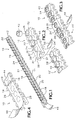
- Figure 1 is a perspective view showing a preferred embodiment of a component holder of the present invention.
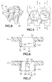
- Figure 2 is an enlarged perspective view of adjacent ends of two component holders of the embodiment shown in Figure 1 wherein an engagement portion at one end of one holder is in position to engage a second end of the other holder.
- Figure 3 shows the component holders of Figure 2 coupled together in end-to-end alignment.
- Figure 4 is a perspective view showing a side of the component holder having an adhesive tape applied thereto.
- Figure 5 is an enlarged top plan view of a portion of the component holder of Figure 1.
- Figure 6 is an enlarged cross section view taken along line 6-6 of Figure 5.
- Figure 7 is an enlarged cross section view taken along line 7-7 of Figure 5.
- Figure 8 is a perspective view of a portion of a component holder adapted to receive and hold a bullet.
- the following description relates primarily to a feeder strip or component holder used for storing, shipping, and providing reloading components to a reloading machine.
- the component holder may be used for transporting and providing primers, bullets or other suitably shaped components to a reloading machine.
- a difference between a component holder for primers and bullets is primarily the size of the receptacle.
- Figure 1 shows a preferred embodiment of an elongate component holder 10.
- the holder is a molded polymeric part.
- a suitable material for the feeder strip is polypropelene, but other resilient polymerics also may be suitable.
- the component holder, or strip, 10 includes various portions that perform different functions.
- a substantially planar portion 12 provides a basic frame for the component holder 10 and also includes notched, or castellated, margins 14 and 16.
- the margins 14, 16 include a plurality of teeth 18 and intermediate gaps 20 that cooperate to provide a means of indexing the component holder as it progresses through a reloading machine.
- the indexing components associated with the reloading machine are not a part of the invention described herein.
- a projecting or bas-relief portion 22 which includes a plurality of upstanding tubular members 24 that are shown arranged in tangential contact. Openings, or receptacles, 26 extend through the projecting portion 22 and the planar portion 12.
- the projecting portion 22 also includes an engagement member 28 at one end of the component holder 10.
- Engagement member 28 includes a top surface 30 that is co-planar with tops 32 of the tubular members 24. Additionally, the engagement member 28 extends outward, longitudinally, beyond an end of the planar portion 12.
- the engagement member 28 is shown in greater detail in Figures 2 and 3 where it can be seen that the engagement member includes a plate-like portion 34 having openings 36 and 38.
- the opening 36 forms a receptacle that includes an inner surface that is substantially similar to inner surfaces 40 of the other receptacles 26.
- opening 38 is semi-circular and larger, being sized to snugly receive and resiliently grip an outer surface of a tubular member 24.
- the opening 38 is bounded by a wall that is greater than 1800 for attachment as will be described below, but has an open end region 37 to provide spring-like gripping.
- the engagement member 28 of one component holder 10 may be located over a second component holder, e.g., 10', so that opening 38 is aligned over an endmost tubular member 24'. Thereafter, the engagement member 38 can be forcefully pushed onto the tubular member 24' so as to resiliently grip it as shown in Figure 3.
- component holders 10 and 10' are longitudinally aligned to form a double-length component holder that may be continuously fed through a reloading machine.
- a reloader In operation, a reloader will start a component holder through a reloading machine and as the holder gets close to an end, the reloader will take another component holder that is filled with primers and attach it to the component holder already in the reloading machine. Obviously, the operation can be continuously repeated indefinitely. As empty component holders come off the opposite end of the reloading machine they may be disengaged from the active component holder and discarded or saved for use with other primers.
- a primer 42 is shown juxtaposed above a receptacle 26.
- the receptacles are shown with primers 42 located therein.
- the bas-relief portion 22 is located along one side of the planar portion 12.
- an adhesive tape 44 that extends the entire length of the component holder 10 and covers all of the receptacles 26.
- a suitable tape 44 is a 3M sealing tape that is 2 to 3 mil thick.
- the tape 44 include a non-adhesive end portion 46 that is not adhered to the flat portion 12 and which provides a tab for easy removal of the tape.
- each receptacle 26 has an inner surface 40 which includes a cylindrical portion 50, a prismatical portion 52 and transition portions 54.
- the convergence of the cylindrical portion 50 and the prismatical portion 52 creates a substantially cylindrical inner surface 40 having a plurality of flats 56, which flats are associated with the prismatical portion 52.
- the flats extend from the tops 32 of the tubes 24 toward an opposite end of the receptacle 26, and terminate approximately three-quarters of the way down. Thereafter, the flats 56 (i.e., prismatical portions 52) are tapered into the cylindrical portion 50 thereby forming the transition portions 54.
- the cylindrical portion 50 of the receptacles 26 is sized to receive round objects such as primers 42 or bullets 48.
- the prismatical portion 52 is sized so that the flats 56 press resiliently against the primer 42 or bullet 48 thus holding it firmly in place.
- the projecting portion 22 assists in this regard because the thinner walls around the receptacle along the tubular members 24 is more yieldable than the thicker walls along the planar portion 12.
- the transition portions 54 are provided as a transition from the cylindrical portion 50 to the prismatical portion 52, thus acting as ramps to assist in loading primers or bullets into the receptacles 26.
- the prismatical portion 52 has three sides (i.e., an equilateral triangular cross-section) thus creating three flats 56 which would press against the primer 42 or bullet 48 and hold it in the center of the receptacle.
- sides i.e., an equilateral triangular cross-section
- other prismatical shapes having different polyhedron configurations could also be used.
- holders 10 having no bas-relief portion i.e., the planar portion 12 would be thicker to create the proper thickness for the receptacles 26.
- engagement members such as mortise and tenon, tab and socket, clip and pintle, may also serve.
Landscapes
- Engineering & Computer Science (AREA)
- General Engineering & Computer Science (AREA)
- Manufacturing & Machinery (AREA)
- Packaging Of Annular Or Rod-Shaped Articles, Wearing Apparel, Cassettes, Or The Like (AREA)
- Adhesive Tape Dispensing Devices (AREA)
Applications Claiming Priority (2)
| Application Number | Priority Date | Filing Date | Title |
|---|---|---|---|
| US654510 | 1996-01-16 | ||
| US08/654,510 US5719348A (en) | 1996-01-16 | 1996-01-16 | Component holder for cartridge reloading |
Publications (2)
| Publication Number | Publication Date |
|---|---|
| EP0789220A2 true EP0789220A2 (fr) | 1997-08-13 |
| EP0789220A3 EP0789220A3 (fr) | 1998-11-18 |
Family
ID=24625168
Family Applications (1)
| Application Number | Title | Priority Date | Filing Date |
|---|---|---|---|
| EP97100427A Withdrawn EP0789220A3 (fr) | 1996-01-16 | 1997-01-13 | Dispositif de stockage d'éléments de cartouches de munition lors du rechargement des cartouches de munition |
Country Status (2)
| Country | Link |
|---|---|
| US (2) | US5719348A (fr) |
| EP (1) | EP0789220A3 (fr) |
Families Citing this family (12)
| Publication number | Priority date | Publication date | Assignee | Title |
|---|---|---|---|---|
| ES2146664T3 (es) * | 1993-10-01 | 2000-08-16 | Henrob Ltd | Cinta portadora para elementos de fijacion. |
| US5988394A (en) * | 1996-11-28 | 1999-11-23 | Kabushiki Kaisha Toshiba | Tray for containing parts for storage and transportation |
| US6260463B1 (en) | 1999-08-11 | 2001-07-17 | Blount, Inc. | Hand-held primer loading tool |
| ITMO20020016A1 (it) * | 2002-01-24 | 2003-07-24 | Sarong Spa | Striscia continua di contenitori |
| DE102006000304A1 (de) * | 2006-06-20 | 2008-01-10 | Hilti Ag | Kartuschenmagazin |
| HK1119021A2 (zh) * | 2007-12-18 | 2009-02-20 | Alex Brands Buzz Bee Toys (Hk) Limited | 用於玩具子弹的弹链 |
| US8028826B1 (en) * | 2010-01-29 | 2011-10-04 | The United States Of America As Represented By The Secretary Of The Army | Storage system for 25mm IM cartridges |
| USD672003S1 (en) * | 2011-02-11 | 2012-12-04 | Crux Research CC | Cartridge holder |
| US20120298716A1 (en) * | 2011-05-23 | 2012-11-29 | Ricardo Segura | Fastener collation having a collation of frangible fastener alignment caps |
| US9162413B2 (en) * | 2012-02-21 | 2015-10-20 | Cloud Packaging Solutions Llc | Polymer packaging systems and methods |
| HK1188535A2 (en) * | 2014-01-14 | 2014-05-02 | 啓俊集团有限公司 | A screwdriver bit, a screwdriver bit connecting device and a screwdriver bits set |
| ITUB20155750A1 (it) * | 2015-11-19 | 2017-05-19 | E M G Srl | Macchina caricatrice per cartucce a bossolo metallico |
Family Cites Families (50)
| Publication number | Priority date | Publication date | Assignee | Title |
|---|---|---|---|---|
| US354454A (en) * | 1886-12-14 | Reloading cartridge-pack | ||
| US837929A (en) * | 1906-07-28 | 1906-12-11 | Harry N Hawley | Cartridge clip and holder. |
| US1870907A (en) * | 1930-04-10 | 1932-08-09 | Reister R Groomes | Box |
| US2298089A (en) * | 1940-07-25 | 1942-10-06 | Veenboer Nicholas | Christmas tree decoration |
| US2451519A (en) * | 1943-03-10 | 1948-10-19 | Rene R Studler | Cartridge belt link |
| US2480972A (en) * | 1945-11-13 | 1949-09-06 | Autoyre Co Inc | Cartridge belt link |
| NL111852C (fr) * | 1959-01-20 | |||
| US3153500A (en) * | 1961-11-20 | 1964-10-20 | Firearm Aceessories Inc | Gun cartridge holder |
| US3184054A (en) * | 1962-07-13 | 1965-05-18 | Rca Corp | Package |
| BE651329A (fr) * | 1963-08-07 | 1964-12-01 | ||
| US3283425A (en) * | 1965-02-23 | 1966-11-08 | Charles J Boyd | Device for collecting, holding and dispensing flanged primers |
| US3349710A (en) * | 1965-07-19 | 1967-10-31 | Sposimo Dino | Strip carrier for explosive socket caps for toy guns |
| DE1603841C3 (de) * | 1967-08-11 | 1982-02-25 | Hilti AG, 9494 Schaan | Pulverkraftbetriebenes Setzgerät zum Eintreiben von Befestigungselementen |
| DE1678202A1 (de) * | 1968-02-21 | 1971-12-30 | Dynamit Nobel Ag | Magazin fuer rueckstandslos verbrennende huelsenlose Treibladungen fuer gewerbliche und/oder militaerische Zwecke |
| US3492913A (en) * | 1968-03-11 | 1970-02-03 | Trw Inc | Open chamber gun ammunition feed system |
| DE2042767C3 (de) * | 1970-08-28 | 1981-01-29 | Hilti Ag, Schaan (Liechtenstein) | Pulverkraftbetriebenes Setzgerät zum Eintreiben von Nägeln |
| SE386510B (sv) * | 1972-04-01 | 1976-08-09 | Dynamit Nobel Ag | Laddremsa for drivhylsor, kanteldpatroner o.d. |
| US3813987A (en) * | 1972-05-10 | 1974-06-04 | Mtm Molded Prod Co | Loading block |
| US3921805A (en) * | 1972-10-10 | 1975-11-25 | Newton L Compere | Rupturable blister pill package with safety backing |
| US3809221A (en) * | 1972-10-10 | 1974-05-07 | N Compere | Rupturable blister pill package with safety backing |
| US4056062A (en) * | 1973-02-02 | 1977-11-01 | Hilti Aktiengesellschaft | Magazine for caseless charges |
| DE2514256C2 (de) * | 1975-04-01 | 1984-05-10 | Hilti Ag, Schaan | Pulverkraftbetriebenes Setzgerät |
| US4004683A (en) * | 1975-05-07 | 1977-01-25 | Omark Industries, Inc. | Packaging for power loads |
| US4106619A (en) * | 1976-08-19 | 1978-08-15 | Pneutek, Inc. | Nail clips |
| US4027417A (en) * | 1976-08-24 | 1977-06-07 | Swatek Rudolf W | Cartridge loading tray |
| US4121365A (en) * | 1977-06-16 | 1978-10-24 | Olin Corporation | Power-actuated tool load magazine |
| GB1521858A (en) * | 1977-06-23 | 1978-08-16 | Parr & Ass Ltd D | Electrical heater units |
| US4425605A (en) * | 1979-01-29 | 1984-01-10 | Sam Cheng | Decorative lighting string for assembly with overcurrent protection |
| AT364979B (de) * | 1980-04-16 | 1981-11-25 | Peter Kurt Dipl Ing | Ladehilfe aus kunststoff fuer revolver |
| DE3021186A1 (de) * | 1980-06-04 | 1981-12-10 | Hilti AG, 9494 Schaan | Magazin fuer huelsenlose treibladungen |
| US4565114A (en) * | 1982-12-08 | 1986-01-21 | Olin Corporation | Cartridge strip magazine for powder-actuated tools |
| US4560061A (en) * | 1983-09-13 | 1985-12-24 | Pneutek, Inc. | Powder charge feed strip |
| US4858811A (en) * | 1985-11-21 | 1989-08-22 | Eldorado Cartridge Corporation | Power actuated tool with magazine feed |
| US4920885A (en) * | 1987-01-02 | 1990-05-01 | Bowman E W | Explosive charge containing magazine for RAM setting gun |
| US4966298A (en) * | 1988-03-25 | 1990-10-30 | Holdt J W Von | Locking container connector system |
| US4862622A (en) * | 1988-08-05 | 1989-09-05 | Goyanes Angel Garcia | Link type cartridge speed loading device |
| DE3910392A1 (de) * | 1989-03-31 | 1990-10-04 | Hilti Ag | Bandfoermiger ladestreifen |
| DE4016045A1 (de) * | 1990-05-18 | 1991-11-21 | Sucker & Franz Mueller Gmbh | Verfahren und vorrichtung zum schlichten von filamentgarn |
| US5150964A (en) * | 1991-06-21 | 1992-09-29 | Tsui Pui Hing | Joy light structure |
| DE4128248A1 (de) * | 1991-08-26 | 1993-03-04 | Varta Batterie | Verkaufs- und vorratspackung fuer zink/luftzellen |
| US5186328A (en) * | 1991-09-23 | 1993-02-16 | Molex Incorporated | Packaging system for electrical connectors |
| DE4136932C2 (de) * | 1991-11-11 | 1999-07-22 | Hilti Ag | Kartuschenmagazin |
| US5208420A (en) * | 1992-03-13 | 1993-05-04 | Hamilton Brian K | Propellant strip assembly |
| US5203143A (en) * | 1992-03-28 | 1993-04-20 | Tempo G | Multiple and split pressure sensitive adhesive stratums for carrier tape packaging system |
| US5198606A (en) * | 1992-04-01 | 1993-03-30 | David J. Storstad | Ammunition primer handling and shell reloading system |
| US5447249A (en) * | 1992-09-04 | 1995-09-05 | Vickers; Robert V. | Interengaging containers |
| DE4301967A1 (de) * | 1993-01-26 | 1994-07-28 | Dynamit Nobel Ag | Kartusche aus Kunststoff für ein Schußgerät, insbesondere ein Bolzensetzgerät |
| US5379888A (en) * | 1994-01-31 | 1995-01-10 | Rentos; Margaret A. | Sew free button assembly |
| CN2197550Y (zh) * | 1994-04-01 | 1995-05-17 | 吴政雄 | 圣诞灯串组合装置 |
| US5590787A (en) * | 1995-01-04 | 1997-01-07 | Micron Technology, Inc. | UV light sensitive die-pac for securing semiconductor dies during transport |
-
1996
- 1996-01-16 US US08/654,510 patent/US5719348A/en not_active Expired - Fee Related
-
1997
- 1997-01-13 EP EP97100427A patent/EP0789220A3/fr not_active Withdrawn
- 1997-04-02 US US08/825,736 patent/US5767433A/en not_active Expired - Fee Related
Non-Patent Citations (1)
| Title |
|---|
| None |
Also Published As
| Publication number | Publication date |
|---|---|
| US5767433A (en) | 1998-06-16 |
| US5719348A (en) | 1998-02-17 |
| EP0789220A3 (fr) | 1998-11-18 |
Similar Documents
| Publication | Publication Date | Title |
|---|---|---|
| US5767433A (en) | Component holder for cartridge reloading | |
| EP1115623B1 (fr) | Bloc de remplissage pour bac de pointes de pipettes et plaque de support amelioree | |
| US4588874A (en) | Electrical device for evaporating of active substances, preferably insecticides | |
| US3240103A (en) | Automatic primer loader | |
| CA1291080C (fr) | Emballage pour disques | |
| EP0302819A3 (en) | Cartridge magazine for free-flowing substances | |
| US5208420A (en) | Propellant strip assembly | |
| US12292267B1 (en) | Ammo box filling tool | |
| EP0205661A2 (fr) | Dispositif de chargement pour chargeur d'armes à feu portatives | |
| US3956844A (en) | Loading device for a tubular projectile | |
| FI893719A0 (fi) | Transportanordning foer foerpackningsaemnen. | |
| US20050249638A1 (en) | Method and apparatus for transferring pipette tips | |
| EP3099995B1 (fr) | Dispositif de chargeur de plombs bb pour cartouches d'arme à air comprimé, cartouche pour armes à air comprimé, ensemble de chargeur et procédé de chargement de plombs bb pour armes à air comprimé | |
| EP0266616B1 (fr) | Support de transport et procédé de remplissage de cartouches de calfatage | |
| US4753003A (en) | Bandoleer of contact carriers for use in power crimping tool | |
| US2722307A (en) | Container for rockets | |
| GB1574260A (en) | Dispensing devices | |
| US4784262A (en) | Cassette for loose-piece parts such as electrical terminals and method of loading | |
| AU717938B2 (en) | Parallelepiped-shaped supply container | |
| US5831197A (en) | Primer strip loading tool | |
| EP0190800B1 (fr) | Dispositifs pour distribuer des leurres | |
| AU2017263104B2 (en) | A cartridge package | |
| US5630510A (en) | Packaging and loading solid ink nuggets for ink jet apparatus | |
| US3831739A (en) | Magazine or container for receiving articles such as caseless propellant charges or compacts | |
| WO1999020975A1 (fr) | Unite de mise a feu pour articles pyrotechniques |
Legal Events
| Date | Code | Title | Description |
|---|---|---|---|
| PUAI | Public reference made under article 153(3) epc to a published international application that has entered the european phase |
Free format text: ORIGINAL CODE: 0009012 |
|
| AK | Designated contracting states |
Kind code of ref document: A2 Designated state(s): DE FR GB IT SE |
|
| PUAL | Search report despatched |
Free format text: ORIGINAL CODE: 0009013 |
|
| AK | Designated contracting states |
Kind code of ref document: A3 Designated state(s): DE FR GB IT SE |
|
| STAA | Information on the status of an ep patent application or granted ep patent |
Free format text: STATUS: THE APPLICATION IS DEEMED TO BE WITHDRAWN |
|
| 18D | Application deemed to be withdrawn |
Effective date: 19990519 |