EP0789328B1 - Méthode de traitement d'image pour affichage d'objets réfléchissants et dispositif correspondant - Google Patents
Méthode de traitement d'image pour affichage d'objets réfléchissants et dispositif correspondant Download PDFInfo
- Publication number
- EP0789328B1 EP0789328B1 EP97250030A EP97250030A EP0789328B1 EP 0789328 B1 EP0789328 B1 EP 0789328B1 EP 97250030 A EP97250030 A EP 97250030A EP 97250030 A EP97250030 A EP 97250030A EP 0789328 B1 EP0789328 B1 EP 0789328B1
- Authority
- EP
- European Patent Office
- Prior art keywords
- parameter set
- representing
- storage
- face
- polygonal face
- Prior art date
- Legal status (The legal status is an assumption and is not a legal conclusion. Google has not performed a legal analysis and makes no representation as to the accuracy of the status listed.)
- Expired - Lifetime
Links
Images


Classifications
-
- G—PHYSICS
- G06—COMPUTING OR CALCULATING; COUNTING
- G06T—IMAGE DATA PROCESSING OR GENERATION, IN GENERAL
- G06T15/00—Three-dimensional [3D] image rendering
- G06T15/50—Lighting effects
-
- G—PHYSICS
- G06—COMPUTING OR CALCULATING; COUNTING
- G06T—IMAGE DATA PROCESSING OR GENERATION, IN GENERAL
- G06T15/00—Three-dimensional [3D] image rendering
Definitions
- the invention relates to an image processing method for Representation of objects with reflective surfaces according to the preamble of claim 1 and a device for Implementation of the method according to claim 9.
- bodies are usually through Lattice models simulated by the spatial coordinates of the nodes are described.
- the spatial coordinates of the nodes are displayed on the screen then from the 3-dimensional coordinate system, for example through central projection in a 2-dimensional screen coordinate system converted.
- the invention is therefore based on the object of an image processing method of the type mentioned at the beginning, which is the representation of reflections of the environment in the objects as well as reflections of the objects with each other allows.
- the task is based on an image processing method according to the preamble of claim 1 characteristic features and - with regard to the device to carry out the procedure - by the features of claim 9 solved.
- the invention includes the technical teaching in which Representation of one of several objects with reflective Surfaces of existing computer-modeled spatial To provide a storage matrix for each object, the reproduces an envelope surface surrounding the respective object and the content of the memory matrices taking into account the mutual reflections, for example by means of ray tracing processes precompute.
- the image processing method according to the invention enables the representation of spatial scenes with several objects, which are in the form of a grid model and preferably by the spatial coordinates of the individual corner points and thus defining the spatial position of the individual polygon surfaces are.
- the image impression of the individual polygon areas can be calculated independently of what a realization of the image processing method according to the invention in a parallel computer architecture and therefore a fast one Image calculation enabled. This is particularly - as already mentioned above - in real-time playback of motion displays or the simulation of varying ones Light conditions advantageous.
- the inventive measures can be both pure software measures as well as by means of suitable special Run hardware.
- the hardware solution has the advantage that in particular by parallel arranged assemblies performed operations simultaneously big time savings.
- the image impression is calculated in accordance with the invention through a computing unit that is used to hold a representing the spatial position of the polygon surface to be displayed first parameter set has a first assembly.
- the first parameter set contains, for example the spatial coordinate values of the corner points of the to be displayed Polygons or the spatial coordinate values of the centroid as well as the components of the normal vector of the Polygon area. Decisive for the composition of the first The only parameter set is that it is the spatial one Position of the polygon area clearly shows.
- the first assembly of the computing unit calculates from the first Parameter set then the surface normal of the polygon area representing the second set of parameters, at the calculation of the image impression of the polygon area in the frame of a local lighting model, their orientation relative consider the light sources or the viewer to be able to.
- the spatial position of the surface normal of the polygon surface can be from the spatial coordinates of the corner points of the polygon surface be determined.
- the edge vectors the polygon area is calculated by the space coordinates neighboring vertices subtracted component by component become.
- the edge vectors determined in this way are naturally within the range defined by the polygon area Level.
- the surface normal then results as a vector product two edge vectors.
- the computing unit therefore has a second assembly according to the invention the spatial position of the reflection vector representing fourth parameter set from which the spatial Position of the normal vector representing the polygon area second parameter set and a perspective of the third parameter set representing the viewer to calculate.
- the third parameter set preferably contains the spatial coordinate values of a virtual observer location or the components of a viewing direction rendering vector. By varying these spatial coordinate values it is easily possible the perspective to change and wander through the spatial scene.
- the image processing method according to the invention therefore plans to include every object in the spatial scene to surround a preferably cubic envelope surface and the Intersection of the reflection vector with this envelope surface determine.
- Each surface element of the envelope surface is here assigned a brightness or color value, the distribution the brightness or color values on the envelope surface by mapping the surroundings of the object onto the envelope surface is pre-calculated. This can be done, for example a central projection of the surroundings onto the envelope surface, which is an all-round shot of the surroundings of each Object.
- the polygon surface is therefore according to the invention the intersection of the reflection vector with the envelope surface calculated and the one assigned to this point of the envelope surface Brightness or color value determined.
- the envelope surface is simulated by a memory matrix, where each memory location of the memory matrix is a Surface element corresponds to the envelope surface.
- the calculation of the intersection of the reflection vector and the envelope surface and the determination of the associated brightness or Color value is preferably carried out according to the invention by an addressing unit, which consists of the components of the reflection vector calculates the address values that are required are to address the memory space of the memory matrix, the intersection of the reflection vector and the envelope surface assigned.
- each an object to be displayed spatial scene are assigned to the reflections of the Being able to take objects into account with each other.
- the spatial location of the polygon area representative first parameter set a selection value calculated and depending on the selection value one Memory matrix selected.
- the selection value is calculated by comparison the spatial coordinate values of the polygon area with given Limits that determine the spatial location of the side surfaces the cubic envelope surface.
- the storage matrices each have one All-round view of the surroundings of the respective objects included.
- the calculation of the corresponding memory contents is relatively time-consuming, but only required once, provided the arrangement of the objects within the Scene is not changed. So it makes sense the "environment images" stored in the memory matrices precalculate to during the actual presentation save computing time in the spatial scene.
- the image processing method is used for the calculation the image impression taking into account the surface normal of the entire polygon area, but uniform for the entire polygon area.
- the polygon areas each have a large number of grid elements split what among other things is a consideration the lighting conditions that vary within the polygon area allows.
- the first assembly of the the computing unit calculates the spatial position the first parameter set representing the polygon area a variety of coordinate sets that position each represent a raster element of the polygon surface and for example the spatial coordinate values of the individual Raster elements included.
- the division of the polygon areas into grid elements enables in addition, taking into account the curved Varying polygon areas within the polygon area local surface normal.
- curved polygon surfaces the local surface normals in the corner points of the polygon area by the one recorded on the input side Parameter set specified.
- the local surface normal at one Any point on the polygon surface then results by interpolation of the vertex normals.
- vertex normals also sets one "soft" transition between adjacent polygon surfaces sure, since one vertex normal to several neighboring ones Polygon surfaces belong and the surface at the connecting line two adjacent polygon surfaces is smooth.
- the interpolation of the local surface normal of the curved Polygon surface from the corner point normals must be dependent on the one hand from the position of the person to be considered Raster elements between the corner points of the polygon surfaces and on the other hand a normal vector from the vertex normals can be determined, which represents an intermediate position. considered an interpolation between just two vertex normals, so on a connecting line between the two Vertices, the one vertex normal can be defined by a Displacement and a rotation to the other vertex normal depict.
- the Interpolation of the local surface normal therefore with the help the so-called quaternions.
- Quaternions are four-dimensional Vector operators that are a scalar component and have three vectorial components. For every vertex standard a quaternion is given.
- the interpolation any local surface normal can advantageously by component interpolation of the quaternions respectively.
- the local surface normal is then the result of linking the one vertex normal with the calculated quaternion.
- Image processing techniques were used for calculation the image impression of the polygon surfaces is ideally reflective Surfaces adopted so that the color distribution the polygon area itself does not affect the image impression, since the viewer does not perceive the polygon area itself, but the environment reflecting in the polygon area.
- each polygon surface has a color or Assign brightness value and this with the image information value to mix the reflection of the environment in the polygon area.
- the mixing ratio will here according to the ratio of specular reflection and diffuse reflection set, with the the reflections image information value reflecting in the polygon area weighted more with increasing proportion of specular reflection becomes.
- Image processing is provided to the individual Polygon surfaces each have a two-dimensional texture image overlay that the surface structure of natural surfaces reproduces. This way it is for example possible to reproduce the surface structure of a wood grain, without refining the grid model accordingly have to.
- each raster element of the polygon area assigned a value for the texture image, which - as already described above - with the image information value is mixed, which reflects the reflections of the environment. It is important that the value for the texture image only from the position of the grid element within the polygon area depends, but not on the spatial location the polygon area. Otherwise, the texture image would appear on a Movement of the polygon area within the polygon area "hike".
- the texture image is in one Storage matrix - hereinafter also referred to as texture storage - filed by means of an addressing unit through which the spatial position of the individual grid elements reproducing coordinate set is addressed.
- the individual polygon surfaces that are flat or at least are smooth to overlay a deep structure to create a realistic picture impression and the simulation of structured surfaces without allowing reproduce the details of the surface structure in the grid model to have to.
- the prerequisite for this is - as already when superimposing a two-dimensional texture image -
- Each element of the memory matrix is therefore a point of Depth structure assigned and contains the inclination value for this point of the deep structure.
- the slope vector must be stored, i.e. the Vector that corresponds to the local surface normal of the smooth surface must be added to the impression of the deep structure cause.
- an inclination value to save a rotation matrix that shows the rotation of the local Area normal defined. This is particularly advantageous because by a rotation the length of the local surface normal is not changed.
- the memory matrix becomes read out an inclination value that by the depth structure local surface normal inclination caused this Represented grid element.
- the memory matrix is therefore by the coordinate set of the respective raster element addressed.
- the depth value only from the position of the grid element within depends on the polygon area, but not on the global one Position of the grid element or the spatial position of the Polygon area. This is necessary because otherwise the on depth structure appearing on the polygon surface at a Movement of the polygon on the surface would "wander".
- the slope value which is the surface course of the simulating depth structure, with a scaling factor multiply by the spatial depth of the Change surface structure.
- the depth matrix contains the maximum slope values of the local surface normal compared to the surface normal of the smooth surface. These maximum inclination values are then corresponding the scaling factor weakened to a deep structure can be simulated with any depth that can be set. This is also a dynamic simulation of deep structures with variable spatial Depth possible. It is only necessary to do this Change the scaling factor during the display.
- Image processing becomes the deep structure when displaying an object simulated by the local Surface normals corresponding to the surface of the to be simulated Depth structure is inclined. That way inclined local surface normal is then - as above described - as part of a local lighting model to calculate the impression of brightness or color of the respective raster element.
- Another variant of the image processing method according to the invention provides for the deep structure of the Object surface already when calculating the envelope surfaces simulate memory matrices.
- the Contents of the storage matrices simulating the envelope surfaces is taking into account a deeply structured Surface calculated.
- the calculation of the memory matrices can - as already mentioned above - by ray tracing methods respectively. This is one of a virtual Looking at viewer outgoing "line of sight" that reflected on the grid elements of the object surface becomes.
- the resulting reflection vector then cut object or detail of the environment defined the image impression of the reflective grid element.
- For simulation a deep structure it is then only necessary when calculating the reflection vector from the "Sehstrahl" according to the surface course of the simulating depth structure based on inclined raster element to lay.
- the computing effort to simulate a Deep structure thus falls in this variant of the invention Image processing method only for pre-calculation of the storage matrices.
- the image processing method according to the invention described above sees - as already explained in detail - for each object there is a storage matrix, the one the object reproduces the surrounding envelope surface and an all-round image contains the surroundings from the perspective of the object.
- the content of this memory matrix is static, so that the spatial scene to be displayed is also static. It is possible to close the virtual viewer location change and wander through the scene, however the scene itself does not change.
- the environment of the individual objects is provided to simulate dynamically. This is advantageous, for example, around a glow of fire or falling raindrops to be able to display as a background image.
- the Textures - i.e. the two-dimensional to be simulated Surface structures - to be simulated dynamically.
- a time-varying surface structure to simulate. This can, for example - as in the previous described dynamic simulation of the environment - happen that several storage matrices for storage of the texture image are provided, with each memory matrix a snapshot of the one to be simulated Contains texture image. While displaying the objects must then only between the individual storage matrices can be switched to get a movement impression.
- the texture memory usually directly the texture image contains, which is to be superimposed on the surface, it is advantageously possible as the texture memory, the image repetition memory to use a video or computer graphics system or the texture memory in some other way with such System to connect. That way it is with With the help of conventional graphics systems possible any image sequences from computer-modeled surfaces as a surface structure image on the surface to simulate dynamically.
- the image processing method looks like already explained in detail - memory matrices before, each are assigned to an object and one surrounding the object Recreate the envelope surface, the envelope surface being a All-round shot from the perspective of the respective object reproduces and thus the consideration of reflections enabled when calculating the image impression.
- Every surface element the envelope surface is therefore a color or brightness value assigned to the image effect of the environment a certain perspective of the viewer.
- Which side of the envelope surface gives the impression of the surroundings reproduces depends on the position of the viewer. This can be the case with an interpolation from the memory matrix read out color or brightness values cause problems, because the neighboring surface elements of the Envelope must be addressed, but under certain circumstances to different side surfaces of the envelope surface belong.
- the body or area shown on the screen should be - as already described above - reproduced in the computer as a grid model.
- the surface therefore consists of numerous polygon surfaces whose spatial position through the spatial coordinates of the nodes of the grid model is defined.
- polygon surfaces Triangles used. This means that in the grid model three points connected by edges are.
- the use of triangles to model the Surfaces has the advantage that the surface normal is one Triangle unambiguously by the spatial coordinates of the corner points is defined because three points always lie in one plane, while with polygons with more than three vertices the possibility there is that the corner points are not exactly in one Level lie, so that the surface normal is not exact is defined.
- the method described above is not limited on a monochrome display. Rather, the process successively or in parallel for several colors - preferably the primary colors - are carried out. in this connection can also have a color-dependent reflection or absorption behavior the surface are taken into account.
- the device is in an advantageous variant of the invention as an integrated circuit in a processor system or also run as a stand-alone processor, the on records a parameter set at its input, which among other things determines the spatial position of a polygon surface.
- the spatial coordinates of individual grid elements then become the output the polygon area and the brightness value of the grid elements taking into account reflections of the Environment.
- To display the polygon area on The spatial coordinates of the individual must be on a screen Raster elements then only in a conventional manner 2-dimensional screen coordinate system transformed become.
- the circuit can thus be cheap in existing Integrate computer graphics systems.
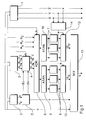
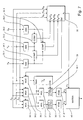
- the circuit shown in Figure 1 is the pictorial Representation of bodies or surfaces used in Form of a grid model.
- the surface of a body is represented by a variety reproduced from adjacent triangles, whose spatial position through the spatial coordinates of the nodes of the grid model is defined.
- the circuit enables the display of several Objects with reflective surfaces are advantageous to consider the reflections of the environment in the objects as well as the objects themselves.
- the embodiment is the representation of a maximum of three objects possible with reflective surfaces. This limitation However, it is based solely on that to maintain clarity simplified embodiment of the circuit and is not of a principled nature, as explained in detail below becomes.
- the circuit also allows simulation a deep structure, for example a surface roughness, without the deep structure in the grid model to have to recreate what realistic representations too with relatively simple grid models. this will also supported by the fact that each triangle a two-dimensional surface structure image is superimposed that can be the simulation of a characteristic Color or brightness distribution of the surface enables.
- the grid model does not need to do this either to be refined, which is beneficial computing time saves on display.
- the circuit receives the input variable for each triangle a parameter set that represents the spatial location of the triangle as well as the desired material properties of the surface Are defined.
- the parameter set contains the spatial coordinates (x s , y s , z s ) of a corner point of the triangle, the edge increments ⁇ lu, ⁇ ru, ⁇ ld, ⁇ rd, the number of raster lines n 1 , n 2 of the triangle, as well as the inclination ⁇ zx of the triangular surface X-axis and the inclination ⁇ zy of the triangular surface to the Y-axis.
- the parameter set contains information about the color of the triangular surface, the absorption behavior, the transparency of the triangular surface and the like.
- the parameter set also contains a U, V coordinate pair for each corner point of the triangle, which defines the position of the respective corner point in the depth structure. Each corner point of the triangle is assigned a point of the depth structure by the parameter set.
- the data of the parameter set, which the spatial location of the Define triangles are fed to a first assembly 1, which initially divided the triangular surface into numerous parallel ones Grid lines and each grid line in turn in numerous Splits grid elements. Then then for each grid element calculates the spatial coordinates x, y, z.
- the division of a triangle into grid elements as well as the Calculation of the spatial coordinates of the individual grid elements is detailed in the description of Figures 5a and 5b explained.
- the parameter set present at the input of the circuit is additionally fed to a second module 2, which uses this to calculate the surface normal (n x , n y , n z ) T of the triangular surface.
- the second arithmetic unit 2 calculates the viewing vector (e x , e y , e z ) T , ie the viewing direction of the viewer, from the predetermined position of the viewer and the position (x s , y s , z s ) of the triangle.
- a matrix M is calculated, which maps the spatial coordinates X, Y, Z of the individual raster elements to the U, V coordinates of the respective raster elements - that is, their position within the depth structure to be simulated:
- the parameter set recorded on the input side contains the U, V coordinates for each corner point of the triangle. Since the X, Y, Z coordinates of the three corner points are also known, there is an equation system of six equations with a total of six unknowns M ij , which is solved in a simple manner by applying Cramer's rule.
- the matrix M serves on the one hand to rotate the depth structure parallel to the triangular surface and on the other hand - as will be explained in more detail - to calculate a further matrix which aligns the inclination vector resulting from the depth structure with the surface normal of the polygon surface to the spatial position of the local To calculate surface normals according to the surface course of the deep structure.
- the U, V coordinates obtained in this way for each raster element are supplied to an assignment unit 5 which each pair of values (U, V) one the depth structure of the Surface defining depth value (du, dv) as well as a assigns the texture value t defining the texture of the surface.
- the assignment unit 5 has two two-dimensional ones Storage matrices - the texture matrix and the depth matrix - which are each addressed by a pair of U, V values.
- the texture matrix defines a flat pattern that is based on the Surface of the triangle appears.
- Each pair of U, V values thus addresses an element of the texture matrix, the the brightness or color value of the associated raster element determined on the surface of the triangle.
- the brightness the triangular surface is therefore not completely uniform, but can - depending on what in the Texture matrix saved patterns - from raster element to Screen element fluctuate. This will make the surface appear not completely uniform and therefore looks much more realistic. For example, the grain of a wooden surface can be simulated. It is important in this context that the texture matrix is only the brightness or Does not contain the color distribution of the desired pattern however simulates a deep structure.
- the surface of the Triangle initially appears completely smooth.
- the depth matrix contains inclination values (du, dv), which the slope of the local surface normal corresponding to the Represent the surface course of the depth structure to be simulated.
- the key to reproducing the deep structure is the Alignment of the local surface normals in the different Raster elements, as a result of this the reflection behavior of the Surface is determined.
- the depth matrix therefore defines like the surface normal at the individual points within of the depth pattern compared to the surface normal of the entire pattern is inclined. So the depth matrix contains each have a value ⁇ u, which is the inclination of the local surface normal determined relative to the U axis, and a value ⁇ v, which determines the inclination relative to the V-axis.
- V values the depth matrix defines that on the surface depth structure to be imprinted on the triangle.
- the circuit has a fourth module 4, which from the surface normal (n x , n y , n z ) T and the local inclination values ⁇ u and ⁇ v the pixel normal, that is, the local surface normal (n x ', n y ', n z ') calculated at the location of each grid element.
- the fourth assembly 4 multiplies the deviations ⁇ u and ⁇ v by an imaging matrix A and adds them to the surface normal (n x , n y , n z ) T :
- the fourth module is shown in detail in FIG. 4 as a block diagram shown.
- the grid elements of a triangle therefore point accordingly the depth structure stored in the depth matrix in each case an inclined local surface normal - in the following referred to as pixel standards - so that the brightness of the grid elements due to the angle dependence of the reflection behavior can fluctuate within a triangle.
- an inclined local surface normal - in the following referred to as pixel standards - so that the brightness of the grid elements due to the angle dependence of the reflection behavior can fluctuate within a triangle.
- pixel standards - an inclined local surface normal - in the following referred to as pixel standards -
- the local brightness value is calculated by means of a further module 6 which, depending on the position of the viewer - given by the viewing vector (e x , e y , e z ) T - and the pixel normals (n x ', n y ', n z ') reads out the local brightness or color value from a memory matrix 7, 8.
- the storage matrices 7, 8 form cubic enveloping surfaces after, each surrounding an object, with each surface element a brightness or color value of the envelope surface assigned.
- the envelope surfaces therefore give an all-round picture from the perspective of the respective object again and thus allow a calculation of when viewed reflective object surfaces resulting image impression.
- which Area element of an envelope or which storage space the associated memory matrix that of the viewer perceived brightness or color value depends here from the perspective of the viewer and the local Area normal of the grid element under consideration.
- Every object Memory matrices assigned to the one the respective object Recreate the surrounding envelope. Which of the storage matrices 7, 8 for calculating the color or brightness value is used depends on the position of the viewed Grid element. It is the one here Memory matrix to use, the one the respective raster element reproduces the surrounding envelope surface.
- the spatial coordinates x, y, z of the grid element are therefore available for selection one of the storage matrices is fed to a selection unit 14, which are the coordinate values x, y, z of the considered Raster elements with the limit values of the different envelope surfaces compares and generates a selection signal a that the Memory matrix determined, which is used to calculate the color or Brightness value is to be used.
- a selection unit 14 which are the coordinate values x, y, z of the considered Raster elements with the limit values of the different envelope surfaces compares and generates a selection signal a that the Memory matrix determined, which is used to calculate the color or Brightness value is to be used.
- To select the memory matrix is both the three storage matrices 8 for calculation the mirror reflection as well as the three storage matrices one to calculate the diffuse reflection Selection unit 12, 13 connected downstream with the selection unit 14 is connected and depending on the Selection value a the output signals one of the three Memory matrices 7 or 8 selected.
- the memory matrix 7, 8 for calculating the color or brightness value of a grid element forms a cubic Envelope surface that surrounds the respective grid element.
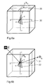
- Figures 6a and 6b show such a cubic envelope.
- Each surface element of the envelope surface is one Color or brightness value assigned.
- the area element is therefore used to calculate the diffuse reflection of the cubic envelope surface to be determined by the pixel normal or its extension is cut.
- the value assigned to this surface element is then the diffuse reflection factor.
- the values on the envelope surface therefore define the lighting environment of the triangle and correspond to an all-round picture the environment from the perspective of the triangle. It is therefore advantageously possible, the reflections of the environment as well as other objects. To do this the contents of the storage matrices 7, 8 are only suitable Be pre-calculated. The simulation is also arbitrarily distributed light sources possible. Furthermore the viewer can change his position as desired virtually walk through a scenery, the viewer's visual impression automatically changes to the changed one Adapts perspective.
- the cubic envelope surface is - as already described above - each with a three-dimensional memory matrix 7 or 8 replicated.
- the first dimension of the memory matrix can take values between 1 and 6 and gives which side surface of the envelope surface from the pixel normal or the reflection vector is pierced.
- the addressing of the other two dimensions of the memory matrix 7, 8 takes place depending on the position the intersection on the respective side surface.
- Knocks the pixel normal or the reflection vector for example a side surface of the cubic parallel to the XZ plane Envelope surface, so the Y coordinate of the Intersection, the second dimension and the Z coordinate of the Intersection the third dimension of the reflection matrix.
- the addressing is not done directly by the Spatial coordinates of the intersection, but indirectly through Interposition of a further computing unit 9 or 10, the angle to the piercing the side surface Axis of the coordinate system in two to each other rectangular planes calculated.
- a color or brightness value E D for diffuse reflection and a color or brightness value E S and mirror reflection are thus read out from the reflection matrices 7, 8 and reflect the visual impression of the viewer taking into account the current perspective.
- the assignment unit 5 provides a texture value t for each raster element, which enables the simulation of a two-dimensional surface structure of the triangle.
- the two color or brightness values E D , E S and the texture value t are fed to a crossfade unit 11, which calculates a brightness value h from this and from the color value c of the triangular area.
- the circuit then gives the spatial coordinates x, y, z of the respective raster element and the calculated one Brightness value h off.
- the spatial coordinates must be displayed on a screen x, y, z of the raster element only in screen coordinates can be converted, for example by means of a downstream computing unit through a central projection the spatial scene can take place.
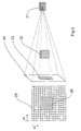
- Figures 2a and 2b show two objects 15, 18 with reflecting Surfaces, each with a cubic envelope 16, 20 are surrounded, which is an all-round shot of the Surrounds the respective object 15 or 18 and thus the consideration of reflections in the objects 15, 18 allows.
- Each surface element of the envelope surface 26 20 is assigned a color or brightness value, which the image impression of the surroundings of the object 15 or 18 in a certain direction.
- the representation here is to maintain clarity only those color or brightness values of the Envelope surfaces 16, 20 again, reflecting the two Objects come together while the reflections a "global" environment surrounding the two objects 15, 18 be ignored.
- the storage matrices that the emulate cubic envelope surfaces 16, 20, on the other hand, give both the reflections of the environment in an object as well the reflections of objects 15, 18 with each other again, in order to achieve the most realistic picture impression possible.
- the illustration contains the second object 18 side surface of the first object 15 enveloping surface 16 almost centrally an image of the second object 18.
- the objects 15, 18 are therefore each on the side surfaces projected onto the envelope surface assigned to the other object.
- the one facing the first object 15 contains Side surface of the envelope surface 20 of the second object 18 also an image of the first object, almost centrally 15.
- the viewer takes the second object 18 true if that from the reflection of the "line of sight" on the Resulting reflection vector the corresponding Envelope surface 16 intersects in the area of the image 17.
- Figure 3 also shows the area 25 the memory matrix simulating the envelope surface, which is assigned to the side surface 24 of the envelope surface.
- each memory location the memory matrix a surface element of the side surface 24 is assigned and thus the color or brightness distribution reproduces on the envelope surface.
- the memory locations actually contain the memory matrix however, color or brightness values in one Variety of gradations, what a realistic rendering of reflections.
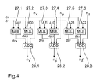
- Figure 4 shows the internal structure of the fourth computing unit.
- the fourth arithmetic unit essentially consists of six multipliers 27.1 to 27.6 and three adders 28.1 to 28.3, which, from the inclination components .DELTA.u and .DELTA.v, the transformation matrix A and the components n x , n y , n z the local surface normal (pixel normal) for each raster element calculate the triangle:
- the coefficients A ij of the transformation matrix and one of the inclination components ⁇ u or ⁇ v are located at the inputs of the multipliers 27.1 to 27.6.
- the output signals dxv, dxu, dyv, dyu, dzv, dzu of the multipliers 27.1 to 27.6, together with the components n x , n y , n z of the surface normal of the triangle, are fed to the adders 28.1 to 28.3, from which the components n ' x , Calculate n ' y , n' z of the pixel normal.
- the circuit has a parameter set at its input, which is under among other things, the spatial position of the triangle to be displayed certainly.
- Figures 5a and 5b show the meaning of these Parameters using an example.
- the parameter set contains, among other things, the spatial coordinates x s , y s , z s of a corner point P start of the triangle.
- This corner point serves as the starting point and defines the position of the triangle in space, while the edge increments ⁇ lu, ⁇ ru, ⁇ ld, ⁇ rd define the shape of the triangle and the position of the triangle relative to the coordinate axes.
- the triangle is divided into raster lines and each raster line is divided into raster elements.
- the individual raster lines run parallel to the X axis.
- the edge increment ⁇ lu or ⁇ ld defines the slope of the triangle edge to the left of the starting point relative to the Y axis, while the edge increment ⁇ ru or ⁇ rd defines the slope of the right triangle edge relative to the Y axis. In this way, the spatial coordinates of the start and end point of each raster line can be calculated.
- the X coordinate x 1 of the starting point of each raster line results from the X coordinate x s of the starting point P start , the number i of the raster line and the edge increment ⁇ lu or ⁇ ld. Within the first n 1 raster lines, the edge increment ⁇ lu and then the edge increment ⁇ ld are used.
- x l x s + ⁇ lu ⁇ i for i ⁇ n 1
- x l x s + ⁇ lu ⁇ n 1 + (in 1 ) ⁇ ⁇ ld for n 1 ⁇ i ⁇ n 1 n + 2
- the X coordinate x r of the end point of each raster line results from the X coordinate x s of the start point P start , the number i of the raster line and the edge increment ⁇ ru or ⁇ rd.
- the raster lines are then divided into raster elements, where for each raster element from the known coordinates the starting and ending points of the raster lines are the spatial coordinates be calculated.
- the Z coordinate of a raster element results from the Z coordinate z l of the starting point of the associated raster line, the number j of the raster element within the raster line and the inclination ⁇ zx of the triangular surface relative to the X axis.
- z j z l + J * ⁇ zy
- the spatial coordinates x j , y j , z j are calculated for each raster element of the triangular surface.
- the cube shown in Figure 6a is used to calculate the Color or brightness value of a raster element with diffuse Reflection on the grid element.
- the light is - as already above executed - largely evenly in all directions radiated.
- the brightness of a raster element is therefore not depending on the perspective of the viewer, but is determined solely by the location of the pixel normal determined relative to the lighting environment.
- the cube is positioned that the focus is on the current grid element of the cube lies.
- the cube thus forms an envelope the grid element, each surface element of the envelope surface a color or brightness value is assigned.
- the intersection 29 of the pixel normal N U with the envelope surface is then determined and the associated color or brightness value is determined.
- the cube is implemented as a 3-dimensional storage matrix, the first dimension of the storage matrix indicating which side surface of the cube is intersected by the pixel normal N U , while the other two dimensions represent the position of the intersection 29 within the side surface.
- the address value a 1 of the first dimension of the memory matrix depends on the components n x , n y , n z of the pixel normal N U :
- the other two dimensions a 2 , a 3 of the memory matrix are addressed as a function of the position of the intersection 29 on the respective side surface. For example, if the pixel normal penetrates a side surface of the cubic envelope surface parallel to the XZ plane, the Y coordinate of the intersection addresses the second dimension and the Z coordinate of the intersection addresses the third dimension of the memory matrix.
- FIG. 6b shows a further cube which is used to calculate the of the color or brightness value of a raster element Mirror reflection is used.
- the cube is arranged such that the triangle 32 under consideration lies in the center of the cube.
- the cube thus forms an envelope surface surrounding the raster element, with each surface element of the envelope surface being assigned a color or brightness value.
- each surface element of the envelope surface being assigned a color or brightness value.
- the surface element of the envelope surface that is penetrated by the reflection vector R U or its extension must be determined.
- the color or brightness value assigned to this surface element then reflects the image impression of the viewer.
- the cubic envelope surface gives an all-round picture of the Environment from the perspective of the grid element again.
- the cube is simulated by a three-dimensional memory matrix.
- the first dimension is addressed as a function of the side surface penetrated by the reflection factor. The following applies to the address value a 1 of the first dimension of the memory matrix:
- the reflection factor for specular reflection is then read from the memory matrix, which, together with the reflection factor for diffuse reflection and the texture value of the raster element, is included in the calculation of the brightness of the raster element.
- the perspective of the beholder can be changed without the memory matrix being new must be calculated.
- the viewer can therefore in one Real-time representation of its perspective relative to that to be represented change spatial scene and thus by the "Walk through" scene.
- Figure 7 shows a block diagram of a circuit for Addressing a 3-dimensional memory matrix by a Vector, the 3-dimensional matrix being the origin reproduces the cubic envelope surface surrounding the vector.
- the circuit shown is therefore suitable for the calculation the color or brightness values for diffuse reflection or Mirror reflection with that shown in Figure 6a and 6b Cubes.
- circuit can be used anywhere where a vector is a 3-dimensional storage matrix addressed, which simulates a cubic envelope, so for example also in Figure 1 instead of the addressing unit 6, the computing unit 9 or 10 and the matrices 7 or 8.
- the circuit At the input, the circuit records the spatial coordinates x N , y N , z N of the addressing vector.
- the circuit first determines which side surface of the cubic envelope surface intersects the vector. For this, the largest spatial coordinate of the addressing vector certainly. For example, is the X coordinate of the vector largest, the vector intersects the side surface the cubic envelope that runs parallel to the YZ plane.
- the space coordinates x N , y N , z N are therefore first fed to a computing unit 33.1, 33.2 and 33.3, respectively, which form the absolute value of the space coordinates. Then the absolute values of the room coordinates - that is, the output signals of the computing units 33.1, 33.2 and 33.3 - are each supplied in pairs to three comparators 34.1, 34.2, 34.3 which compare the absolute values of the room coordinates.
- the output signals of the comparators 34.1, 34.2, 34.3 are then fed to an addressing unit 35, which calculates the address value a 1 for the first dimension of the 3-dimensional matrix 40.
- the addressing unit 35 compares the output signals of the comparators 34.1, 34.2, 34.3 and calculates the address value a 1 according to the following rule and from the signs of the spatial coordinates:
- the circuit also determines at which position the vector addressing the side surface of the cubic envelope surface pierces. The coordinates of this intersection are used to address the second and third dimensions the matrix 40.
- the circuit forms the quotient from one the smaller spatial coordinates and the absolute value largest spatial coordinate.
- the addressing unit 35 therefore generates a selection signal Sel that the multiplexers 36.1, 36.2, 36.3 is supplied.
- the multiplexer 36.3 selects the largest spatial coordinate in terms of amount executes and supplies its value to the computing unit 39, which forms the reciprocal and separated as a mantissa and outputs exponent.
- the other two multiplexers 36.1, 36.2 each choose one of the two smaller spatial coordinates than Counter off.
- the output signals of the multiplexers 36.1, 36.2 are then together with the mantissa determined by the computing unit 39 the reciprocal of the largest spatial coordinate each supplied to a multiplier 37.1, 37.2, which the smaller spatial coordinates with the mantissa of Reciprocal of the largest spatial coordinate in terms of amount.
- the output signal of the multipliers 37.1, 37.2 becomes two Shift registers 38.1, 38.2 fed a multiplication with the exponent calculated by the computing unit 39 carry out.
- the output signals a 2 , a 3 then address the second or third dimension of the matrix 40, which is implemented, for example, as a semiconductor memory.
- the invention is not limited in its execution the preferred embodiments given above. Rather, a number of variants are conceivable which of the solution shown also in principle makes use of different types.
Landscapes
- Engineering & Computer Science (AREA)
- Computer Graphics (AREA)
- Physics & Mathematics (AREA)
- General Physics & Mathematics (AREA)
- Theoretical Computer Science (AREA)
- Image Generation (AREA)
- Processing Or Creating Images (AREA)
- Radar Systems Or Details Thereof (AREA)
Claims (17)
- Procédé de traitement d'image en vue de la représentation d'objets (15, 18), les objets (15, 18) se composant en particulier d'au moins une surface polygonale (30, 32),
selon lequel pour chaque objet (15, 18)
au moyen d'un premier ensemble (2) d'une unité de calcul à partir d'un premier jeu de paramètres prédéterminé représentant la position spatiale de la surface polygonale (30, 32) est calculé un second jeu de paramètres (nx, ny, nz) représentant la position spatiale de la normale à la surface
ainsi qu'au moyen d'un second ensemble (6) de l'unité de calcul à partir du second jeu de paramètres (nx, ny, nz) et à partir d'un troisième jeu de paramètres (ex, ey, ez) représentant la perspective de l'observateur est calculé un quatrième jeu de paramètres, qui représente la position spatiale d'un rayon lumineux atteignant l'observateur après la réflexion sur la surface polygonale (30, 32),
caractérisé en ce qu'aux objets (15, 18) en vue de la détermination de l'impression de luminosité et/ou de couleur en tenant compte de réflexions de l'environnement et d'autres objets, est associée une matrice de mémoire (7, 8), qui représente une surface enveloppe (16, 20) entourant l'objet respectif et qui contient l'impression de luminosité et/ou de couleur de l'environnement de l'objet (15, 18) à partir de valeurs d'information d'image (ED, ES) représentant la perspective de celui-ci,
en ce qu'en vue du choix de la matrice de mémoire (7, 8) associée à l'objet (15, 18) au moyen d'un troisième ensemble (14) de l'unité de calcul est calculée, à partir du premier jeu de paramètres représentant la position spatiale de la surface polygonale (30, 32), une valeur de sélection (a) et en fonction de la valeur de sélection (a) une matrice de mémoire (7, 8) est sélectionnée,
en ce que la matrice de mémoire sélectionnée au moyen du troisième ensemble (14) est adressée au moyen d'une unité d'adressage (6, 9, 10) par le quatrième jeu de paramètres et à partir de l'emplacement de mémoire adressé est sélectionnée la valeur d'information d'image (ED, ES) représentant l'impression de luminosité et/ou de couleur. - Procédé de traitement d'image selon la revendication 1, caractérisé en ce qu'au moyen d'un quatrième ensemble (1) à partir du premier jeu de paramètres représentant la position spatiale de la surface polygonale (30, 32) est calculée une pluralité d'ensembles de coordonnées (x, y, z) qui représentent la position respectivement d'un élément de trame de la surface polygonale (30, 32),
en ce que le second jeu de paramètres (nx, ny, nz) représentant la position spatiale de la normale à la surface pour chaque élément de trame de la surface polygonale (30, 32) est calculé à partir du premier jeu de paramètres représentant la position spatiale de la surface polygonale (30, 32) et de l'ensemble de coordonnées (x, y, z) de l'élément de trame respectif. - Procédé de traitement d'image selon la revendication 2, caractérisé en ce que la surface polygonale est courbée et le premier jeu de paramètres représente la position spatiale des normales aux points angulaires,
en ce que le deuxième jeu de paramètres (n'x, n'y, n'z), représentant la position spatiale de la normale locale à la surface dans un élément de trame, est calculé par interpolation des normales aux points angulaires à partir du premier jeu de paramètres représentant la position spatiale des normales aux points angulaires de la surface polygonale (30, 32) et de l'ensemble de coordonnées (x, y, z) de l'élément de trame respectif. - Procédé de traitement d'image selon la revendication 2 ou 3, caractérisé en ce qu'en vue de la simulation d'une structure profonde de la surface polygonale (30, 32), un emplacement de mémoire d'une seconde matrice de mémoire (5) est adressé au moyen d'une seconde unité d'adressage (3) par chaque ensemble de coordonnées (x, y, z) et une valeur d'inclinaison (du, dv), représentant l'inclinaison de la normale locale à la surface dans l'élément de trame déterminé par l'ensemble de cordonnées (x, y, z) par rapport à la normale de la surface polygonale (30, 32) correspondant à la structure profonde à simuler, est sélectionnée à partir de l'emplacement de mémoire adressé de la seconde matrice de mémoire (5),
en ce que le second jeu de paramètres (n'x, n'y, n'z), représentant la position spatiale de la normale locale à la surface pour chaque ensemble de coordonnées (x, y, z), est calculé à partir du premier jeu de paramètres représentant la position spatiale de la surface polygonale (30, 32) et de la valeur d'inclinaison (du, dv). - Procédé de traitement d'image selon la revendication 4, caractérisé en ce que la valeur d'inclinaison (du, dv) en vue du changement d'échelle de la structure profonde est multipliée avant le calcul du second jeu de paramètres (n'x, n'y, n'z) représentant la position spatiale de la normale locale à la surface au moyen d'un multiplicateur par un coefficient de changement d'échelle prédéterminé.
- Procédé de traitement d'image selon une des revendications 2 à 5, caractérisé en ce qu'en vue de la simulation d'une texture de la surface polygonale (30, 32) au moyen d'une troisième unité d'adressage (3) pour chaque élément de trame de la surface polygonale (30, 32) par l'ensemble de coordonnées associé (x, y, z), un emplacement de mémoire d'une troisième matrice de mémoire (5) est adressé et une valeur de texture sélectionnée,
en ce que la valeur de texture sélectionnée à partir de la troisième matrice de mémoire (5) en vue de la simulation d'une surface polygonale (30, 32) seulement réfléchissante partiellement est mélangée à l'aide d'un dispositif de mélange (11) avec la valeur d'information d'image (ES, ED) sélectionnée à partir de la première matrice de mémoire (7, 8). - Procédé de traitement d'image selon une des revendications précédentes, caractérisé en ce qu'à chaque objet (15, 18) sont associées plusieurs matrices de mémoire, qui représentent respectivement une surface enveloppe entourant l'objet et contiennent un instantané de l'impression de luminosité et/ou de couleur de l'environnement de l'objet (15, 18) à partir d'informations d'image représentant la perspective de celle-ci,
en ce qu'en vue de la génération d'une impression de mouvement au moyen d'un unité de sélection est sélectionnée en succession une des matrices de mémoire et est reliée en vue de l'adressage par le quatrième jeu de paramètres à l'unité d'adressage (6, 9, 10). - Procédé de traitement d'image selon une des revendications précédentes, caractérisé en ce que la surface polygonale (30, 32) est triangulaire.
- Dispositif de traitement d'image en vue de la mise en oeuvre du procédé selon une des revendications précédentes, comprenant une entrée en vue de la réception d'un premier jeu de paramètres représentant la position spatiale de la surface polygonale (30, 32),
une unité de calcul comportantcaractérisé en ce qu'aux objets (15, 18) est associée, en vue de la détermination de l'impression de luminosité et/ou de couleur en tenant compte des réflexions sur d'autres objets, une matrice de mémoire (7, 8), qui représente la surface enveloppe (16, 20) entourant l'objet respectif (15, 18) et contient les valeurs d'information d'image (ES, ED) représentant l'impression de luminosité et/ou de couleur,un premier ensemble (2) en vue du calcul d'un second jeu de paramètres (nx, ny, nz) représentant la position spatiale de la normale à la surface polygonale (30, 32) à partir du premier jeu de paramètres représentant la position spatiale de la surface polygonale (30, 32),un second ensemble (6) en vue du calcul d'un quatrième jeu de paramètres représentant la position spatiale d'un rayon lumineux réfléchi sur la surface polygonale (30, 32) et atteignant l'observateur à partir du second jeu de paramètres (n'x, n'y, n'z) représentant la position de la normale à la surface et d'un troisième jeu de paramètres (ex, ey, ez) prédéterminé, représentant la perspective de l'observateur,
en ce qu'en vue de la sélection de la matrice de mémoire (7, 8) associée à l'objet respectif (15, 18), est prévu un troisième ensemble (14), qui calcule une valeur de sélection (a) en fonction du premier jeu de paramètres représentant la position spatiale de la surface polygonale (30, 32) et sélectionne une matrice de mémoire (7, 8) en fonction de la valeur de sélection (a),
en ce qu'en vue de l'adressage de l'emplacement de mémoire de la matrice de mémoire (7, 8) sélectionnée par le troisième ensemble (14) en fonction du quatrième jeu de paramètres, est prévue une unité d'adressage (6, 9, 10). - Dispositif de traitement d'image selon la revendication 9, caractérisé en ce qu'à chaque objet (15, 18) est associée respectivement une matrice de mémoire (8) en vue du calcul de la réflexion spéculaire et une matrice de mémoire (7) en vue du calcul de la réflexion diffuse sur la surface polygonale (30, 32), des matrice de mémoire (7, 8) simulant respectivement une surface enveloppe entourant l'objet (15, 18) et chaque emplacement de mémoire des matrices de mémoire contient respectivement une valeur d'information d'image, qui restitue l'impression d'image de l'environnement de l'objet (15, 18) à partir de la perspective de celui-ci.
- Dispositif de traitement d'image selon la revendication 9 ou 10, caractérisé en ce qu'en vue du calcul d'une pluralité d'ensembles de coordonnées (x, y, z) représentant la position respective d'un élément de trame de la surface polygonale, est prévu un quatrième ensemble.
- Dispositif de traitement d'image selon la revendication 11, caractérisé en ce qu'en vue de la simulation d'une structure profonde de la surface polygonale (30, 32) est prévue une seconde matrice de mémoire (5), à chaque emplacement de mémoire de la seconde matrice de mémoire (5) étant associé un élément de trame de la surface polygonale et contient une valeur d'inclinaison (du, dv) qui définit l'inclinaison de la normale locale à la surface correspondant à l'allure de la surface de la structure profonde assimilée,
en ce qu'en vue de l'adressage de la seconde
matrice de mémoire (5) par les ensembles de coordonnées (x, y, z) des différents éléments de trame, est prévue une seconde unité d'adressage (3). - Dispositif de traitement d'image selon la revendication 12, caractérisé en ce qu'en aval de la seconde matrice de mémoire servant à la simulation d'une structure profonde, en vue du changement d'échelle de la structure profonde est disposé un multiplicateur.
- Dispositif de traitement d'image selon une des revendications 11 à 13, caractérisé en ce qu'en vue de la simulation d'une texture de la surface polygonale (30, 32), est prévue une troisième matrice de mémoire (5), à chaque emplacement de mémoire de la troisième matrice de mémoire (5) étant associé un élément de trame de la surface polygonale et contenant une valeur de texture (t) correspondant à l'image de texture à simuler,
en ce qu'en vue de l'adressage de la troisième matrice de mémoire (5) par les ensembles de coordonnées (x, y, z) des différents éléments de trame, est prévue une troisième unité d'adressage (3). - Dispositif de traitement d'image selon la revendication 14, caractérisé en ce que la troisième matrice de mémoire servant à la simulation d'une texture en vue de la simulation dynamique de texture est reliée à un système vidéo ou graphique de calculateur.
- Dispositif de traitement d'image selon la revendication 14, caractérisé en ce qu'à chaque objet en vue de la simulation dynamique de texture, sont associées plusieurs matrices de mémoire, qui contiennent des valeurs de couleur et/ou de luminosité restituant respectivement un instantané de l'image de texture à simuler,
en ce qu'en vue de la sélection séquentielle d'une des matrices de mémoire contenant une image de texture, est prévue une unité de sélection en vue de la génération d'une impression de mouvement. - Dispositif selon une des revendications 9 à 16, caractérisé en ce qu'à chaque objet (15, 18) sont associées plusieurs matrices de mémoire, qui représentent une surface enveloppe entourant l'objet et contiennent un instantané de l'impression de luminosité et/ou de couleur de l'environnement de l'objet (15, 18) à partir d'informations d'image représentant la perspective de celui-ci,
en ce qu'en vue de la sélection séquentielle d'une des matrices de mémoire contenant un instantané de l'environnement, est prévue une unité de sélection en vue de la génération d'une impression de mouvement.
Applications Claiming Priority (2)
| Application Number | Priority Date | Filing Date | Title |
|---|---|---|---|
| DE19606357 | 1996-02-12 | ||
| DE19606357A DE19606357A1 (de) | 1996-02-12 | 1996-02-12 | Bildverarbeitungsverfahren zur Darstellung von spiegelnden Objekten und zugehörige Vorrichtung |
Publications (3)
| Publication Number | Publication Date |
|---|---|
| EP0789328A2 EP0789328A2 (fr) | 1997-08-13 |
| EP0789328A3 EP0789328A3 (fr) | 1998-04-15 |
| EP0789328B1 true EP0789328B1 (fr) | 2002-05-22 |
Family
ID=7785949
Family Applications (1)
| Application Number | Title | Priority Date | Filing Date |
|---|---|---|---|
| EP97250030A Expired - Lifetime EP0789328B1 (fr) | 1996-02-12 | 1997-02-10 | Méthode de traitement d'image pour affichage d'objets réfléchissants et dispositif correspondant |
Country Status (5)
| Country | Link |
|---|---|
| US (1) | US6031542A (fr) |
| EP (1) | EP0789328B1 (fr) |
| JP (1) | JPH09231404A (fr) |
| AT (1) | ATE217996T1 (fr) |
| DE (2) | DE19606357A1 (fr) |
Families Citing this family (39)
| Publication number | Priority date | Publication date | Assignee | Title |
|---|---|---|---|---|
| JP3514945B2 (ja) * | 1997-05-26 | 2004-04-05 | 株式会社ソニー・コンピュータエンタテインメント | 画像作成方法および画像作成装置 |
| DE69817152T2 (de) * | 1997-11-14 | 2004-06-09 | Koninklijke Philips Electronics N.V. | Computergraphisches bump-mapping-verfahren und geraet |
| US6618048B1 (en) | 1999-10-28 | 2003-09-09 | Nintendo Co., Ltd. | 3D graphics rendering system for performing Z value clamping in near-Z range to maximize scene resolution of visually important Z components |
| US6717577B1 (en) | 1999-10-28 | 2004-04-06 | Nintendo Co., Ltd. | Vertex cache for 3D computer graphics |
| US6972774B2 (en) * | 2000-02-21 | 2005-12-06 | Fujitsu Limited | Image processing system for inserting plurality of images into composite area, and medium |
| US7119813B1 (en) | 2000-06-02 | 2006-10-10 | Nintendo Co., Ltd. | Variable bit field encoding |
| US7538772B1 (en) | 2000-08-23 | 2009-05-26 | Nintendo Co., Ltd. | Graphics processing system with enhanced memory controller |
| US7061502B1 (en) | 2000-08-23 | 2006-06-13 | Nintendo Co., Ltd. | Method and apparatus for providing logical combination of N alpha operations within a graphics system |
| US7576748B2 (en) * | 2000-11-28 | 2009-08-18 | Nintendo Co. Ltd. | Graphics system with embedded frame butter having reconfigurable pixel formats |
| US6707458B1 (en) | 2000-08-23 | 2004-03-16 | Nintendo Co., Ltd. | Method and apparatus for texture tiling in a graphics system |
| US6700586B1 (en) | 2000-08-23 | 2004-03-02 | Nintendo Co., Ltd. | Low cost graphics with stitching processing hardware support for skeletal animation |
| US6937245B1 (en) * | 2000-08-23 | 2005-08-30 | Nintendo Co., Ltd. | Graphics system with embedded frame buffer having reconfigurable pixel formats |
| US6867781B1 (en) | 2000-08-23 | 2005-03-15 | Nintendo Co., Ltd. | Graphics pipeline token synchronization |
| US6980218B1 (en) | 2000-08-23 | 2005-12-27 | Nintendo Co., Ltd. | Method and apparatus for efficient generation of texture coordinate displacements for implementing emboss-style bump mapping in a graphics rendering system |
| US6825851B1 (en) | 2000-08-23 | 2004-11-30 | Nintendo Co., Ltd. | Method and apparatus for environment-mapped bump-mapping in a graphics system |
| US6636214B1 (en) | 2000-08-23 | 2003-10-21 | Nintendo Co., Ltd. | Method and apparatus for dynamically reconfiguring the order of hidden surface processing based on rendering mode |
| US7002591B1 (en) | 2000-08-23 | 2006-02-21 | Nintendo Co., Ltd. | Method and apparatus for interleaved processing of direct and indirect texture coordinates in a graphics system |
| US7034828B1 (en) | 2000-08-23 | 2006-04-25 | Nintendo Co., Ltd. | Recirculating shade tree blender for a graphics system |
| US7184059B1 (en) | 2000-08-23 | 2007-02-27 | Nintendo Co., Ltd. | Graphics system with copy out conversions between embedded frame buffer and main memory |
| US7196710B1 (en) | 2000-08-23 | 2007-03-27 | Nintendo Co., Ltd. | Method and apparatus for buffering graphics data in a graphics system |
| US6811489B1 (en) | 2000-08-23 | 2004-11-02 | Nintendo Co., Ltd. | Controller interface for a graphics system |
| US6828980B1 (en) * | 2000-10-02 | 2004-12-07 | Nvidia Corporation | System, method and computer program product for z-texture mapping |
| US7230628B1 (en) * | 2000-10-05 | 2007-06-12 | Shutterfly, Inc. | Previewing a framed image print |
| US6970454B1 (en) * | 2001-08-09 | 2005-11-29 | Pasternak Solutions Llc | Sliced crossbar architecture with inter-slice communication |
| JP2006350678A (ja) * | 2005-06-16 | 2006-12-28 | Nippon Telegr & Teleph Corp <Ntt> | 光線情報生成方法,光線情報の圧縮データ生成方法,光線情報生成装置,光線情報の圧縮データ生成装置,およびそれらのプログラム並びにプログラムを記録した記録媒体 |
| US20090046099A1 (en) * | 2006-11-13 | 2009-02-19 | Bunkspeed | Real-time display system |
| US7646332B2 (en) * | 2007-08-09 | 2010-01-12 | Raytheon Company | Method and apparatus for interleaved gridding in distributed multiple computing for real-time RCS prediction |
| US7652620B2 (en) * | 2007-08-09 | 2010-01-26 | Raytheon Company | RCS signature generation for closely spaced multiple objects using N-point models |
| US7602332B1 (en) | 2008-06-13 | 2009-10-13 | Raytheon Company | Reducing scattering center data using multi-volume aggregation |
| US7616151B1 (en) | 2008-06-13 | 2009-11-10 | Raytheon Company | Reducing scattering center data using magnitude-based reduction |
| US7567205B1 (en) * | 2008-09-18 | 2009-07-28 | Raytheon Company | Dynamic ray traversing |
| US7750842B2 (en) * | 2008-09-18 | 2010-07-06 | Raytheon Company | Parallel processing to generate radar signatures for multiple objects |
| US7592947B1 (en) * | 2008-09-18 | 2009-09-22 | Raytheon Company | Generating radar signatures for multiple objects |
| US7880671B2 (en) * | 2008-09-18 | 2011-02-01 | Raytheon Company | Electromagnetic (EM) solver using a shooting bouncing ray (SBR) technique |
| US8390508B1 (en) | 2010-04-05 | 2013-03-05 | Raytheon Company | Generating radar cross-section signatures |
| FR2965652A1 (fr) * | 2010-09-30 | 2012-04-06 | Thomson Licensing | Procede d’estimation de la quantite de lumiere recue en un point d’un environnement virtuel |
| JP6432882B2 (ja) * | 2013-07-19 | 2018-12-05 | 株式会社ナリス化粧品 | 画像シミュレーション方法 |
| US9842424B2 (en) * | 2014-02-10 | 2017-12-12 | Pixar | Volume rendering using adaptive buckets |
| US9607411B2 (en) * | 2014-04-23 | 2017-03-28 | Ebay Inc. | Specular highlights on photos of objects |
Family Cites Families (10)
| Publication number | Priority date | Publication date | Assignee | Title |
|---|---|---|---|---|
| JPH0746391B2 (ja) * | 1984-09-14 | 1995-05-17 | 株式会社日立製作所 | 図形シエ−デイング装置 |
| US4866637A (en) * | 1987-10-30 | 1989-09-12 | International Business Machines Corporation | Pipelined lighting model processing system for a graphics workstation's shading function |
| US4866647A (en) * | 1988-02-04 | 1989-09-12 | American Telephone And Telegraph Company | Continuously variable digital delay circuit |
| US5253339A (en) * | 1990-07-26 | 1993-10-12 | Sun Microsystems, Inc. | Method and apparatus for adaptive Phong shading |
| JP2861647B2 (ja) * | 1992-07-08 | 1999-02-24 | 松下電器産業株式会社 | 画像生成装置 |
| US5357599A (en) * | 1992-07-30 | 1994-10-18 | International Business Machines Corporation | Method and apparatus for rendering polygons |
| GB2270243B (en) * | 1992-08-26 | 1996-02-28 | Namco Ltd | Image synthesizing system |
| US5739820A (en) * | 1992-11-19 | 1998-04-14 | Apple Computer Inc. | Method and apparatus for specular reflection shading of computer graphic images |
| JPH06223201A (ja) * | 1993-01-22 | 1994-08-12 | Matsushita Electric Ind Co Ltd | 並列画像生成装置 |
| JP3554616B2 (ja) * | 1994-12-13 | 2004-08-18 | 富士通株式会社 | ラジオシティ法を用いる描画方法および装置 |
-
1996
- 1996-02-12 DE DE19606357A patent/DE19606357A1/de not_active Withdrawn
-
1997
- 1997-02-10 JP JP9026787A patent/JPH09231404A/ja active Pending
- 1997-02-10 AT AT97250030T patent/ATE217996T1/de not_active IP Right Cessation
- 1997-02-10 EP EP97250030A patent/EP0789328B1/fr not_active Expired - Lifetime
- 1997-02-10 DE DE59707308T patent/DE59707308D1/de not_active Expired - Lifetime
- 1997-02-11 US US08/799,305 patent/US6031542A/en not_active Expired - Lifetime
Non-Patent Citations (1)
| Title |
|---|
| Ernst, Jackèl, Rüsseler, Wittig: "Hardware Supported Bump Mapping: A step towards Higher Quality Real-Time Rendering", 10th Eurographics Workshp on Graphics Hardware, Maastricht, Netherlands, 1995, Seiten 63-70 * |
Also Published As
| Publication number | Publication date |
|---|---|
| ATE217996T1 (de) | 2002-06-15 |
| US6031542A (en) | 2000-02-29 |
| DE19606357A1 (de) | 1997-08-14 |
| EP0789328A2 (fr) | 1997-08-13 |
| JPH09231404A (ja) | 1997-09-05 |
| DE59707308D1 (de) | 2002-06-27 |
| EP0789328A3 (fr) | 1998-04-15 |
Similar Documents
| Publication | Publication Date | Title |
|---|---|---|
| EP0789328B1 (fr) | Méthode de traitement d'image pour affichage d'objets réfléchissants et dispositif correspondant | |
| DE69329049T2 (de) | Methode zur Verarbeitung von Daten, die dreidimensionale graphische Objekte repräsentieren | |
| DE3686233T2 (de) | Videosignalverarbeitung. | |
| DE69328464T2 (de) | Methode zur Berechnung der Beleuchtung für Daten dreidimensionaler Objekte | |
| DE69424716T2 (de) | Verfahren und Vorrichtung zur adaptiven Steuerung der Texturabbildung | |
| EP0862141A2 (fr) | Méthode et appareil de présentation d'image | |
| DE3485846T2 (de) | Videoobjekt-generator. | |
| DE69714551T2 (de) | Treiberstufe für stereoskopische bildanzeige | |
| DE112007002991B4 (de) | Computergraphikschattenvolumen unter Verwendung von hierarchischem Okklusions-Culling | |
| DE19646194B4 (de) | Echtzeit-Wiedergabeverfahren zum wahlweisen Ausführen von Bump-Mapping- und Phong-Schattierungs-Prozessen und zugehörige Vorrichtung | |
| DE69127915T2 (de) | System und Verfahren von Prioritätsfarbabbildung | |
| DE69331486T2 (de) | Bilddatenverarbeitung | |
| DE60120474T2 (de) | Rasterung von dreidimensionalen bildern | |
| DE69924700T2 (de) | Verfahren zur Darstellung von durch Oberflächenelemente repräsentierten grafischen Objekten | |
| DE69331031T2 (de) | Vorrichtung zur parallelen Bilderzeugung | |
| DE69427210T2 (de) | Verfahren und Gerät zur Erzeugung von dreidimensionaler Animation | |
| DE69722139T2 (de) | Dreidimensionale abbildung von bildtexturen | |
| DE69924699T2 (de) | Verfahren zur Schaffung von als Oberflächenelemente dargestellten grafischen Objekten | |
| DE69230774T2 (de) | Anti-aliasing Tiefenpuffer | |
| DE69723798T2 (de) | Gerät und Verfahren zum spekular Reflektionsimulieren in einem Graphik-Bildsystem | |
| DE60002487T2 (de) | Verfahren und vorrichtung zur darstellung von bildern mit brechungen | |
| DE3854619T2 (de) | Quadratische interpolation zur schattierten bilderzeugung. | |
| DE19620858B4 (de) | Computergraphiksystem mit Pixel-Tiefenhinweisgebung | |
| EP0865002B1 (fr) | Méthode et appareil pour afficher des objets modelisés par ordinateur | |
| DE60030401T2 (de) | Anzeigetechniken für dreidimensionale virtuelle Realität |
Legal Events
| Date | Code | Title | Description |
|---|---|---|---|
| PUAI | Public reference made under article 153(3) epc to a published international application that has entered the european phase |
Free format text: ORIGINAL CODE: 0009012 |
|
| AK | Designated contracting states |
Kind code of ref document: A2 Designated state(s): AT BE CH DE FR GB IT LI NL |
|
| PUAL | Search report despatched |
Free format text: ORIGINAL CODE: 0009013 |
|
| AK | Designated contracting states |
Kind code of ref document: A3 Designated state(s): AT BE CH DE FR GB IT LI NL |
|
| 17P | Request for examination filed |
Effective date: 19980917 |
|
| GRAG | Despatch of communication of intention to grant |
Free format text: ORIGINAL CODE: EPIDOS AGRA |
|
| 17Q | First examination report despatched |
Effective date: 20010814 |
|
| GRAG | Despatch of communication of intention to grant |
Free format text: ORIGINAL CODE: EPIDOS AGRA |
|
| GRAH | Despatch of communication of intention to grant a patent |
Free format text: ORIGINAL CODE: EPIDOS IGRA |
|
| GRAH | Despatch of communication of intention to grant a patent |
Free format text: ORIGINAL CODE: EPIDOS IGRA |
|
| GRAA | (expected) grant |
Free format text: ORIGINAL CODE: 0009210 |
|
| PG25 | Lapsed in a contracting state [announced via postgrant information from national office to epo] |
Ref country code: NL Free format text: LAPSE BECAUSE OF FAILURE TO SUBMIT A TRANSLATION OF THE DESCRIPTION OR TO PAY THE FEE WITHIN THE PRESCRIBED TIME-LIMIT Effective date: 20020522 Ref country code: IT Free format text: LAPSE BECAUSE OF FAILURE TO SUBMIT A TRANSLATION OF THE DESCRIPTION OR TO PAY THE FEE WITHIN THE PRE;WARNING: LAPSES OF ITALIAN PATENTS WITH EFFECTIVE DATE BEFORE 2007 MAY HAVE OCCURRED AT ANY TIME BEFORE 2007. THE CORRECT EFFECTIVE DATE MAY BE DIFFERENT FROM THE ONE RECORDED.SCRIBED TIME-LIMIT Effective date: 20020522 Ref country code: GB Free format text: LAPSE BECAUSE OF FAILURE TO SUBMIT A TRANSLATION OF THE DESCRIPTION OR TO PAY THE FEE WITHIN THE PRESCRIBED TIME-LIMIT Effective date: 20020522 Ref country code: FR Free format text: LAPSE BECAUSE OF FAILURE TO SUBMIT A TRANSLATION OF THE DESCRIPTION OR TO PAY THE FEE WITHIN THE PRESCRIBED TIME-LIMIT Effective date: 20020522 |
|
| REF | Corresponds to: |
Ref document number: 217996 Country of ref document: AT Date of ref document: 20020615 Kind code of ref document: T |
|
| REG | Reference to a national code |
Ref country code: GB Ref legal event code: FG4D Free format text: NOT ENGLISH |
|
| REG | Reference to a national code |
Ref country code: CH Ref legal event code: EP |
|
| REF | Corresponds to: |
Ref document number: 59707308 Country of ref document: DE Date of ref document: 20020627 |
|
| NLV1 | Nl: lapsed or annulled due to failure to fulfill the requirements of art. 29p and 29m of the patents act | ||
| GBV | Gb: ep patent (uk) treated as always having been void in accordance with gb section 77(7)/1977 [no translation filed] |
Effective date: 20020522 |
|
| EN | Fr: translation not filed | ||
| PG25 | Lapsed in a contracting state [announced via postgrant information from national office to epo] |
Ref country code: AT Free format text: LAPSE BECAUSE OF NON-PAYMENT OF DUE FEES Effective date: 20030210 |
|
| PG25 | Lapsed in a contracting state [announced via postgrant information from national office to epo] |
Ref country code: LI Free format text: LAPSE BECAUSE OF NON-PAYMENT OF DUE FEES Effective date: 20030228 Ref country code: CH Free format text: LAPSE BECAUSE OF NON-PAYMENT OF DUE FEES Effective date: 20030228 Ref country code: BE Free format text: LAPSE BECAUSE OF NON-PAYMENT OF DUE FEES Effective date: 20030228 |
|
| PLBE | No opposition filed within time limit |
Free format text: ORIGINAL CODE: 0009261 |
|
| STAA | Information on the status of an ep patent application or granted ep patent |
Free format text: STATUS: NO OPPOSITION FILED WITHIN TIME LIMIT |
|
| 26N | No opposition filed |
Effective date: 20030225 |
|
| REG | Reference to a national code |
Ref country code: CH Ref legal event code: PL |
|
| PGFP | Annual fee paid to national office [announced via postgrant information from national office to epo] |
Ref country code: DE Payment date: 20130220 Year of fee payment: 17 |
|
| REG | Reference to a national code |
Ref country code: DE Ref legal event code: R119 Ref document number: 59707308 Country of ref document: DE |
|
| REG | Reference to a national code |
Ref country code: DE Ref legal event code: R119 Ref document number: 59707308 Country of ref document: DE Effective date: 20140902 |
|
| PG25 | Lapsed in a contracting state [announced via postgrant information from national office to epo] |
Ref country code: DE Free format text: LAPSE BECAUSE OF NON-PAYMENT OF DUE FEES Effective date: 20140902 |