EP0789396A2 - Kühlkörper für Halbleiterbauelemente od. dgl. - Google Patents
Kühlkörper für Halbleiterbauelemente od. dgl. Download PDFInfo
- Publication number
- EP0789396A2 EP0789396A2 EP96810883A EP96810883A EP0789396A2 EP 0789396 A2 EP0789396 A2 EP 0789396A2 EP 96810883 A EP96810883 A EP 96810883A EP 96810883 A EP96810883 A EP 96810883A EP 0789396 A2 EP0789396 A2 EP 0789396A2
- Authority
- EP
- European Patent Office
- Prior art keywords
- groove
- heat sink
- base plate
- additional
- sink according
- Prior art date
- Legal status (The legal status is an assumption and is not a legal conclusion. Google has not performed a legal analysis and makes no representation as to the accuracy of the status listed.)
- Granted
Links
Images
Classifications
-
- H—ELECTRICITY
- H10—SEMICONDUCTOR DEVICES; ELECTRIC SOLID-STATE DEVICES NOT OTHERWISE PROVIDED FOR
- H10W—GENERIC PACKAGES, INTERCONNECTIONS, CONNECTORS OR OTHER CONSTRUCTIONAL DETAILS OF DEVICES COVERED BY CLASS H10
- H10W40/00—Arrangements for thermal protection or thermal control
- H10W40/20—Arrangements for cooling
- H10W40/22—Arrangements for cooling characterised by their shape, e.g. having conical or cylindrical projections
- H10W40/226—Arrangements for cooling characterised by their shape, e.g. having conical or cylindrical projections characterised by projecting parts, e.g. fins to increase surface area
Definitions
- the invention relates to a heat sink for semiconductor components or the like.
- Devices in particular a high-performance cooling unit - made of extruded aluminum or other light metal with spaced-apart connection to a base plate and projecting cooling fins, or the like by means of a coupling base in an insert groove.
- the recess of the base plate is fixed, an auxiliary groove for temporarily holding a tool being arranged next to each insert groove receiving a valve rib in the base plate.
- DE-PS 35 18 310 describes such a cooling unit with insert grooves of rectangular cross-section molded into the surface of the base plate for receiving the coupling base of a cooling fin.
- the central axis of the insert groove is its axis of symmetry and that of the coupling base.
- the coupling base is provided with longitudinal ribs and - limited by these - longitudinal side grooves into which base plate matrix is pressed during the manufacturing process by a deforming - cross-sectionally wedge-like - tool; this creates a positive connection between the cooling fin and the base plate.
- the force component directed towards the base plate in accordance with the wedge angle of the deforming tool leads to a resilient elastic deformation.
- a secure contact between the underside of the coupling base on the one hand and the base plate on the other hand can hardly be achieved, and heat flow over the base plate and underside of the coupling base only takes place on a negligible scale; the heat flow is only carried over the flanks of this coupling base.
- the inventor set himself the task of achieving an improved bracing of the cooling fin in the base plate with the lowest possible punching force, and thus further improving the cooling capacity per unit volume.
- an additional groove inclined into the base plate from the base of the groove is formed in the corner area of the insert groove, determined by the side wall and the base of the groove; whose angle of inclination with the central axis of the insert groove, which preferably forms an axis of symmetry, is below 90 °, advantageously between 50 ° and 70 °.
- the cross section of the additional groove is rounded; its contour consists of a pitch circle and tangents extending from it, parallel to each other.
- the largest cross-sectional length preferably corresponds to about a third of the insert groove depth.
- the groove shape according to the invention leads to a deformation of the groove flanks or sidewalls directed towards the lower part of the base plate and thus to an additional stress component.
- the positive connection between the lower surface of the coupling base and the base plate creates a significantly improved heat transfer and thus a significant improvement in the quality of the bond between the cooling fins and the housing or base plate.
- a high-performance cooling unit made of light metal - in particular made of AlMgSiO.5 F 22 - for semiconductor components not shown in the drawing for reasons of clarity has a heat sink 10 with a housing 12 made of a base plate 14 of width a of, for example, 150 mm, as shown in FIG. 1 and a thickness b of here 25 mm and flank walls 16 formed on both sides of the base plate 14. The latter form with the base plate 14 an - extruded - rectangular channel.
- insert grooves 22 which are separated from one another by bottom ribs 20, have a rectangular cross-section of depth h of, for example, 4 mm; the insert grooves 22 are at a distance e of their central axes A of 10 mm and alternately arranged with auxiliary grooves 24 approximately V-shaped cross section.
- the auxiliary grooves 24 run in the bottom ribs 20 mentioned.
- a cooling fin 26 - directed parallel to the flank walls 16 - with a groove cross section i. w. filling coupling base 28 of width k used; four longitudinal strips 30 of approximately sawtooth-like cross-section are formed from the two side surfaces thereof.
- a cross-sectionally rounded additional groove 36 extends from the corners of the insert grooves 22 formed by the side wall 32 and the groove base 34.
- Their symmetry or center line M is inclined to the central axis A of the insert groove 22 and includes an inclination angle w of approximately 60 ° with the latter.
- Their cross-sectional length n corresponds to approximately one third of the depth h of the insert groove 22.
- a cross-wedge-like crimping tool 38 is inserted into the adjacent auxiliary groove 24, the side walls 25 of which determine a cross-sectional angle t of approximately 35 °, the wedge angle q of which is greater than the cross-sectional angle t of the auxiliary groove 24 by more than 55 ° 38 first deforms the upper region of the rib section 40 delimited by the insert groove 22 and auxiliary groove 24 by a shear force F q and presses the side wall matrix in the form of material beads into longitudinal grooves 31 of the coupling base 28 delimited by the longitudinal strips 30 as the depth of penetration y of the tool 38 increases in the pressure direction z builds up a vertical force F v , which presses the coupling base 28 onto the groove base 34 while reducing the cross section of the additional grooves 36. This results in additional bracing of the cooling fin 26.
Landscapes
- Cooling Or The Like Of Semiconductors Or Solid State Devices (AREA)
- Cooling Or The Like Of Electrical Apparatus (AREA)
- Glass Compositions (AREA)
- Compositions Of Oxide Ceramics (AREA)
- Mechanical Treatment Of Semiconductor (AREA)
- Crystals, And After-Treatments Of Crystals (AREA)
- Transition And Organic Metals Composition Catalysts For Addition Polymerization (AREA)
Abstract
Description
- Die Erfindung betrifft einen Kühlkörper für Halbleiterbauelemente od.dgl. Geräte -- insbesondere eine Hochleistungskühleinheit -- aus stranggepreßtem Aluminium oder anderem Leichtmetall mit in Abstand zueinander an eine Grundplatte angeschlossenen und davon aufragenden Kühlrippen, die jeweils mittels eines Kupplungssockels in einer Einsatznut od.dgl. Ausnehmung der Grundplatte festliegen, wobei neben jeder eine Ventilrippe aufnehmenden Einsatznut in der Grundplatte eine Hilfsnut zur Zeitweiligen Aufnahme eines Werkzeuges angeordnet ist.
- Die DE-PS 35 18 310 beschreibt eine derartige Kühleinheit mit in die Oberfläche der Grundplatte eingeformten Einsatznuten rechteckigen Querschnitts zur Aufnahme des Kupplungssockels einer Kühlrippe. Die Mittelachse der Einsatznut ist deren -- und des Kupplungssockels -- Symmetrieachse. Der Kupplungssockel ist mit Längsrippen und -- von diesen begrenzten -- längsgerichteten Seitennuten versehen, in welche während des Herstellungsprozesses durch ein verformendes -- querschnittlich keilartiges -- Werkzeug Grundplatten-Matrix eingepreßt wird; so entsteht ein formschlüssiger Verbund zwischen Kühlrippe und Grundplatte. In letzterer werden durch die Verformung sowohl in Längs- als auch in Querrichtung Spannungen erzeugt, die zum festen Sitz der Kühlrippen wesentlich beitragen; die Rückfederung der zwischen Einsatznut und Hilfsnut verbleibenden engen Rippenabschnitte des Grundprofiles wird kompensiert. Dieser Rückfederungseffekt nimmt naturgemäß mit steigender Festigkeit des Grundwerkstoffes zu. Entsprechend hoch müssen dann die erzeugten Spannungen in der Grundplatte -- und damit die Stanzkraft -- sein, was wiederum zu größeren Planheitsabweichungen der Grundplatte führen kann.
- Die entsprechend dem Keilwinkel des verformenden Werkzeuges auf die Grundplatte gerichtete Kraftkomponente führt zu einer rückbildenden elastischen Verformung. Ein sicherer Kontakt zwischen der Unterseite des Kupplungssockels einerseits und der Grundplatte anderseits kann kaum erreicht werden, und ein Wärmefluß über Grundplatte und Unterseite des Kupplungssockels findet nur in vernachlässigbarer Größenordnung statt; der Wärmefluß wird lediglich über die Flanken dieses Kupplungssockels geführt.
- In Kenntnis dieses Standes der Technik hat sich der Erfinder die Aufgabe gestellt, eine verbesserte Verspannung der Kühlrippe in der Grundplatte bei möglichst geringer Stanzkraft zu erreichen sowie damit die Kühlleistung je Volumeneinheit weitergehend zu verbessern.
- Zur Lösung dieser Aufgabe führt die Lehre nach dem unabhängigen Anspruch; die Unteransprüche geben günstige Weiterbildungen an.
- Erfindungsgemäß ist in die Grundplatte im -- von Seitenwand und Nutengrund bestimmten -- Eckbereich der Einsatznut eine vom Nutengrund in die Grundplatte hinein geneigte Zusatznut eingeformt; deren Neigungswinkel mit der -- bevorzugt eine Symmetrieachse bildenden -- Mittelachse der Einsatznut liegt unter 90°, vorteilhafterweise zwischen 50° und 70°.
- Nach einem weiteren Merkmal der Erfindung ist der Querschnitt der Zusatznut gerundet; seine Kontur besteht aus einem Teilkreis und davon ausgehenden, zueinander parallelen Tangenten. Die größte Querschnittslänge entspricht bevorzugt etwa einem Drittel der Einsatznuttiefe.
- Dank dieses Paares von Zusatznuten beidseits der Einsatznut wird die erwähnte Rückfederung vermindert. Die erfindungsgemäße Nutform führt zu einer auf den unteren Teil der Grundplatte gerichtete Verformung der Nutflanken oder - seitenwände und so zu einer zusätzlichen Spannungskomponente. Durch den Formschluß zwischen der Unterfläche des Kupplungssockels und der Grundplatte wird ein wesentlich verbesserter Wärmeübergang geschaffen und damit eine deutliche Qualitätsverbesserung des Verbundes zwischen Kühlrippen und Gehäuse bzw. Grundplatte.
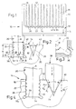
- Weitere Vorteile, Merkmale und Einzelheiten der Erfindung ergeben sich aus der nachfolgenden Beschreibung eines bevorzugten Ausführungsbeispieles sowie anhand der Zeichnung; diese zeigt in
- Fig. 1:
- die Frontansicht einer Hochleistungskühleinheit aus einem Kühlkörper mit Kühlrippen;
- Fig. 2:
- einen vergrößerten Ausschnitt aus Fig. 1 mit einer einzelnen Kühlrippe während der Herstellung der Hochleistungskühleinheit;
- Fig. 3:
- einen vergrößerten Ausschnitt aus Fig. 2 ohne Kühlrippe;
- Fig. 4:
- den -- vergrößerten -- Ausschnitt der Fig. 2 in einer nachfolgenden Herstellungsstufe;
- Eine Hochleistungskühleinheit aus Leichtmetall -- insbesondere aus AlMgSiO.5 F 22 -- für in der Zeichnung aus Gründen der Übersichtlichkeit nicht weiter dargestellte Halbleiterbauelemente weist gemäß Fig. 1 einen Kühlkörper 10 mit einem Gehäuse 12 aus einer Grundplatte 14 der Breite a von beispielsweise 150 mm und einer Dicke b von hier 25 mm sowie beidseits an die Grundplatte 14 angeformten Flankenwänden 16 auf. Letztere bilden mit der Grundplatte 14 eine --stranggepreßte -- Rechteckrinne.
- In die Grundplatte 14 sind zum Gehäuseinnenraum 18 hin offene -- durch Bodenrippen 20 voneinander getrennte -- Einsatznuten 22 rechteckigen Querschnitts der Tiefe h von beispielsweise 4 mm angeformt; die Einsatznuten 22 sind zueinander in einem Abstand e ihrer Mittelachsen A von 10 mm sowie wechselweise mit Hilfsnuten 24 etwa V-förmigen Querschnitts angeordnet. Die Hilfsnuten 24 verlaufen in den erwähnten Bodenrippen 20.
- In die Einsatznuten 22 rechteckigen Querschnitts der Breite i von 4 mm wird jeweils eine -- parallel zu den Flankenwänden 16 gerichtete -- Kühlrippe 26 mit einem den Nutenquerschnitt i. w. ausfüllenden Kupplungssockel 28 der Breite k eingesetzt; aus dessen beiden Seitenflächen sind jeweils vier Längsleisten 30 etwa sägezahnartigen Querschnitts herausgeformt.
- Von den -- durch Seitenwand 32 und Nutengrund 34 gebildeten -- Ecken der Einsatznuten 22 geht jeweils eine querschnittlich gerundete Zusatznut 36 aus. Deren Symmetrie- oder Mittellinie M ist zur Mittelachse A der Einsatznut 22 geneigt und schließt mit letzterer einen Neigungswinkel w von etwa 60° ein. Deren Querschnittslänge n entspricht etwa einem Drittel der Tiefe h der Einsatznut 22.
- Zum Festlegen der Kühlrippe 26 in der Grundplatte 14 werden die Seitenwände 32 der Einsatznut 22 verformt. Gemäß Fig. 3 wird in die benachbarte Hilfsnut 24, deren Seitenwände 25 einen Querschnittswinkel t von etwa 35° bestimmen, ein querschnittlich keilartiges Quetschwerkzeug 38 eingesetzt, dessen Keilwinkel q mit mehr als 55° größer ist als jener Querschnittswinkel t der Hilfsnut 24. Das Werkzeug 38 verformt zunächst den oberen Bereich des von Einsatznut 22 und Hilfsnut 24 begrenzten Rippenabschnitts 40 durch eine Querkraft Fq und preßt die Seitenwandmatrix in Form von Werkstoffwülsten in von den Längsleisten 30 begrenzte Längsnuten 31 des Kupplungssockels 28. Mit zunehmender Eindringtiefe y des Werkzeuges 38 in Druckrichtung z baut sich eine Vertikalkraft Fv auf, die unter Verminderung des Querschnitts der Zusatznuten 36 den Kupplungssockel 28 auf den Nutgrund 34 drückt. Hierdurch wird ein zusätzliches Verspannen der Kühlrippe 26 erreicht.
- Durch die Sollbiegestelle an der durch die verformten Zusatznuten 36r erreichten geschwächten Stelle an den Rippenabschnitten 40 der Grundplatte 14 wird die Stanzkraft spürbar reduziert, ohne daß dies zu Lasten des Festsitzes der Kühlrippen 26 ginge.
Claims (7)
- Kühlkörper für Halbleiterbauelemente od.dgl. Geräte, insbesondere Hochleistungskühleinheit, aus stranggepreßtem Aluminium oder anderem Leichtmetall, mit in Abstand zueinander an eine Grundplatte angeschlossenen und davon aufragenden Kühlrippen, die jeweils mittels eines Kupplungssockels in einer Einsatznut od.dgl. Ausnehmung der Grundplatte festliegen, wobei neben jeder eine Kühlrippe aufnehmenden Einsatznut in der Grundplatte eine Hilfsnut zur zeitweiligen Aufnahme eines Werkzeuges angeordnet ist,
dadurch gekennzeichnet,
daß in dem von Seitenwand (32) und Nutengrund (34) bestimmten Eckbereich der Einsatznut (22) in die Grundplatte (14) eine Zusatznut (36) eingeformt ist. - Kühlkörper nach Anspruch 1, dadurch gekennzeichnet, daß die Mittellinie (M) der Zusatznut (36) mit der Mittelachse (A) der Einsatznut (22) einen zum Nutengrund (34) gerichteten Neigungswinkel (w) von weniger als 90° einschließt.
- Kühlkörper nach Anspruch 2, gekennzeichnet durch einen von den beiden Mittellinien (M) der Zusatznuten (36) bestimmten Neigungswinkel zwischen 100° und 140°.
- Kühlkörper nach Anspruch 2, gekennzeichnet durch einen Neigungswinkel (w) zwischen Mittelachse (A) und Mittellinie (M) von etwa 60°.
- Kühlkörper nach einem der Ansprüche 1 bis 4, dadurch gekennzeichnet, daß die Zusatznut (36) einen endwärts gerundeten Querschnitt aufweist.
- Kühlkörper nach Anspruch 5, gekennzeichnet durch einen Querschnitt aus einem Teilkreis und zwei zueinander parallelen Tangenten an diesen.
- Kühlkörper nach einem der Ansprüche 1 bis 6, gekennzeichnet durch ein Verhältnis der Querschnittslänge (n) der Zusatznut (36) zur Tiefe (h) der Einsatznut (22) zwischen 1 : 4 und 1 : 3.
Applications Claiming Priority (2)
| Application Number | Priority Date | Filing Date | Title |
|---|---|---|---|
| DE29601584U | 1996-01-31 | ||
| DE29601584 | 1996-01-31 |
Publications (3)
| Publication Number | Publication Date |
|---|---|
| EP0789396A2 true EP0789396A2 (de) | 1997-08-13 |
| EP0789396A3 EP0789396A3 (de) | 1998-09-30 |
| EP0789396B1 EP0789396B1 (de) | 2006-06-14 |
Family
ID=8018748
Family Applications (1)
| Application Number | Title | Priority Date | Filing Date |
|---|---|---|---|
| EP96810883A Expired - Lifetime EP0789396B1 (de) | 1996-01-31 | 1996-12-19 | Kühlkörper für Halbleiterbauelemente od. dgl. |
Country Status (7)
| Country | Link |
|---|---|
| EP (1) | EP0789396B1 (de) |
| AT (1) | ATE330329T1 (de) |
| DE (1) | DE59611356D1 (de) |
| DK (1) | DK0789396T3 (de) |
| ES (1) | ES2262151T3 (de) |
| NO (1) | NO324069B1 (de) |
| PT (1) | PT789396E (de) |
Cited By (5)
| Publication number | Priority date | Publication date | Assignee | Title |
|---|---|---|---|---|
| DE19836314A1 (de) * | 1998-08-11 | 2000-02-24 | Joachim Bayer | Verfahren zur Herstellung von Kühlkörpern zum Anbau an Halbleiterbauelemente |
| US6520248B2 (en) * | 2000-05-18 | 2003-02-18 | Aavid Thermalloy Llc | Heat sink having bonded cooling fins |
| DE10157240A1 (de) * | 2001-11-22 | 2003-06-05 | Corus Aluminium Profiltechnik | Kühlkörper und Verfahren zur Herstellung desselben |
| US6845812B2 (en) * | 2002-12-20 | 2005-01-25 | Motorola, Inc. | Heatsink with multiple, selectable fin densities |
| US7819173B2 (en) * | 2005-04-15 | 2010-10-26 | R-Theta Thermal Solutions Inc. | Base plate for a dual base plate heatsink |
Citations (1)
| Publication number | Priority date | Publication date | Assignee | Title |
|---|---|---|---|---|
| DE3518310A1 (de) | 1985-05-22 | 1986-11-27 | Aluminium-Walzwerke Singen Gmbh, 7700 Singen | Kuehlkoerper fuer halbleiterbauelemente und verfahren zu seiner herstellung |
Family Cites Families (5)
| Publication number | Priority date | Publication date | Assignee | Title |
|---|---|---|---|---|
| DE2502472C2 (de) * | 1975-01-22 | 1982-09-02 | Siemens AG, 1000 Berlin und 8000 München | Kühlkörper für Thyristoren |
| US5038858A (en) * | 1990-03-13 | 1991-08-13 | Thermalloy Incorporated | Finned heat sink and method of manufacture |
| DE59106364D1 (de) * | 1990-10-24 | 1995-10-05 | Alusuisse Lonza Services Ag | Kühlkörper für Halbleiterbauelemente. |
| DE4314663A1 (de) * | 1993-05-04 | 1994-11-10 | Alusuisse Lonza Services Ag | Kühlkörper für Halbleiterbauelemente |
| DE9412460U1 (de) * | 1994-08-02 | 1995-12-14 | Hoogovens Aluminium Profiltechnik Gmbh, 88267 Vogt | Kühlvorrichtung für elektrische bzw. elektronische Bauelemente mit einer Grundplatte und mit Kühlelementen |
-
1996
- 1996-12-19 DK DK96810883T patent/DK0789396T3/da active
- 1996-12-19 ES ES96810883T patent/ES2262151T3/es not_active Expired - Lifetime
- 1996-12-19 EP EP96810883A patent/EP0789396B1/de not_active Expired - Lifetime
- 1996-12-19 DE DE59611356T patent/DE59611356D1/de not_active Expired - Lifetime
- 1996-12-19 AT AT96810883T patent/ATE330329T1/de active
- 1996-12-19 PT PT96810883T patent/PT789396E/pt unknown
-
1997
- 1997-01-29 NO NO19970387A patent/NO324069B1/no not_active IP Right Cessation
Patent Citations (1)
| Publication number | Priority date | Publication date | Assignee | Title |
|---|---|---|---|---|
| DE3518310A1 (de) | 1985-05-22 | 1986-11-27 | Aluminium-Walzwerke Singen Gmbh, 7700 Singen | Kuehlkoerper fuer halbleiterbauelemente und verfahren zu seiner herstellung |
Cited By (6)
| Publication number | Priority date | Publication date | Assignee | Title |
|---|---|---|---|---|
| DE19836314A1 (de) * | 1998-08-11 | 2000-02-24 | Joachim Bayer | Verfahren zur Herstellung von Kühlkörpern zum Anbau an Halbleiterbauelemente |
| US6520248B2 (en) * | 2000-05-18 | 2003-02-18 | Aavid Thermalloy Llc | Heat sink having bonded cooling fins |
| DE10157240A1 (de) * | 2001-11-22 | 2003-06-05 | Corus Aluminium Profiltechnik | Kühlkörper und Verfahren zur Herstellung desselben |
| DE10157240B4 (de) * | 2001-11-22 | 2012-10-25 | Aleris Aluminum Vogt Gmbh | Kühlkörper und Verfahren zur Herstellung desselben |
| US6845812B2 (en) * | 2002-12-20 | 2005-01-25 | Motorola, Inc. | Heatsink with multiple, selectable fin densities |
| US7819173B2 (en) * | 2005-04-15 | 2010-10-26 | R-Theta Thermal Solutions Inc. | Base plate for a dual base plate heatsink |
Also Published As
| Publication number | Publication date |
|---|---|
| EP0789396A3 (de) | 1998-09-30 |
| ES2262151T3 (es) | 2006-11-16 |
| EP0789396B1 (de) | 2006-06-14 |
| DE59611356D1 (de) | 2006-07-27 |
| NO970387D0 (no) | 1997-01-29 |
| DK0789396T3 (da) | 2006-10-23 |
| ATE330329T1 (de) | 2006-07-15 |
| NO324069B1 (no) | 2007-08-06 |
| NO970387L (no) | 1997-08-01 |
| PT789396E (pt) | 2006-10-31 |
Similar Documents
| Publication | Publication Date | Title |
|---|---|---|
| DE3518310C2 (de) | ||
| DE69430096T2 (de) | Methode und Apparat zur Herstellung von Kühlkörpern hoher Rippendichte | |
| DE112017005953T5 (de) | Halbleiterbauelement und verfahren zur herstellung des halbleiterbauelements | |
| DE112012003918B4 (de) | Drahtbondwerkzeug | |
| DE60016163T2 (de) | Haltevorrichtung für Sammelleitung eines Wärmetauschers und Verfahren zu dessen Zusammenbau | |
| DE69111199T2 (de) | Offener Schraubschlüssel mit verkleinerten Backen. | |
| EP0483058B1 (de) | Kühlkörper für Halbleiterbauelemente | |
| EP1187199A2 (de) | Kühlkörper für Halbleiterbauelemente, Verfahren zu seiner Herstellung sowie Formwerkzeug dafür | |
| EP0741409B1 (de) | Kühlkörper für Halbleiterbauelemente | |
| DE112004001211T5 (de) | Wärmetauscher | |
| DE29601776U1 (de) | Kühlkörper für Halbleiterbauelemente o.dgl. | |
| EP0734062A2 (de) | Kühlkörper für Halbleiterbauelemente od. dgl. | |
| EP0789396B1 (de) | Kühlkörper für Halbleiterbauelemente od. dgl. | |
| EP0795905A2 (de) | Kühlkörper für Halbleiterbauelemente od. dgl. Einrichtungen | |
| DE2460631A1 (de) | Kuehlkoerper zur fremdkuehlung von thyristoren | |
| DE9302754U1 (de) | Kühlrippenanordnung für eine integrierte Schaltung | |
| DE10229532B4 (de) | Kühlvorrichtung für Halbleiterbauelemente | |
| DE19841911A1 (de) | Kühlkörper für im wesentlichen L-förmige oder T-förmige Kühlrippen | |
| DE69611489T2 (de) | Strahlungsrippen und Verfahren zu deren Herstellung | |
| DE102007046684B3 (de) | Verfahren und Vorrichtung zum Herstellen eines Flachprofils, insbesondere eines Kühlkörpers für Halbleiterelemente od. dgl. Bauteile, sowie Profil dazu | |
| DE10033908C1 (de) | Mikro-Wärmeübertrager mit sich kreuzenden, voneinander getrennten Kanälen für die Wärmeträgermedien | |
| DE10157240B4 (de) | Kühlkörper und Verfahren zur Herstellung desselben | |
| DE19841583A1 (de) | Kühlkörper mit mindestens zwei separaten Basisplatten | |
| DE19842977A1 (de) | Kühlkörper mit Kühlrippen quer zu Rippen des Grundprofils und Verfahren zu dessen Herstellung | |
| DE19836314A1 (de) | Verfahren zur Herstellung von Kühlkörpern zum Anbau an Halbleiterbauelemente |
Legal Events
| Date | Code | Title | Description |
|---|---|---|---|
| PUAI | Public reference made under article 153(3) epc to a published international application that has entered the european phase |
Free format text: ORIGINAL CODE: 0009012 |
|
| AK | Designated contracting states |
Kind code of ref document: A2 Designated state(s): AT BE CH DE DK ES FR GB IE IT LI NL PT SE |
|
| PUAL | Search report despatched |
Free format text: ORIGINAL CODE: 0009013 |
|
| RAP1 | Party data changed (applicant data changed or rights of an application transferred) |
Owner name: ALUSUISSE TECHNOLOGY & MANAGEMENT AG |
|
| AK | Designated contracting states |
Kind code of ref document: A3 Designated state(s): AT BE CH DE DK ES FR GB IE IT LI NL PT SE |
|
| 17P | Request for examination filed |
Effective date: 19990330 |
|
| RAP1 | Party data changed (applicant data changed or rights of an application transferred) |
Owner name: ALCAN TECHNOLOGY & MANAGEMENT AG |
|
| GRAP | Despatch of communication of intention to grant a patent |
Free format text: ORIGINAL CODE: EPIDOSNIGR1 |
|
| GRAS | Grant fee paid |
Free format text: ORIGINAL CODE: EPIDOSNIGR3 |
|
| GRAA | (expected) grant |
Free format text: ORIGINAL CODE: 0009210 |
|
| AK | Designated contracting states |
Kind code of ref document: B1 Designated state(s): AT BE CH DE DK ES FR GB IE IT LI NL PT SE |
|
| REG | Reference to a national code |
Ref country code: GB Ref legal event code: FG4D Free format text: NOT ENGLISH |
|
| REG | Reference to a national code |
Ref country code: CH Ref legal event code: EP |
|
| REG | Reference to a national code |
Ref country code: IE Ref legal event code: FG4D Free format text: LANGUAGE OF EP DOCUMENT: GERMAN |
|
| GBT | Gb: translation of ep patent filed (gb section 77(6)(a)/1977) |
Effective date: 20060704 |
|
| REF | Corresponds to: |
Ref document number: 59611356 Country of ref document: DE Date of ref document: 20060727 Kind code of ref document: P |
|
| REG | Reference to a national code |
Ref country code: SE Ref legal event code: TRGR |
|
| REG | Reference to a national code |
Ref country code: DK Ref legal event code: T3 |
|
| REG | Reference to a national code |
Ref country code: PT Ref legal event code: SC4A Effective date: 20060825 |
|
| REG | Reference to a national code |
Ref country code: ES Ref legal event code: FG2A Ref document number: 2262151 Country of ref document: ES Kind code of ref document: T3 |
|
| ET | Fr: translation filed | ||
| PLBE | No opposition filed within time limit |
Free format text: ORIGINAL CODE: 0009261 |
|
| STAA | Information on the status of an ep patent application or granted ep patent |
Free format text: STATUS: NO OPPOSITION FILED WITHIN TIME LIMIT |
|
| 26N | No opposition filed |
Effective date: 20070315 |
|
| PGFP | Annual fee paid to national office [announced via postgrant information from national office to epo] |
Ref country code: IE Payment date: 20101227 Year of fee payment: 15 |
|
| PGFP | Annual fee paid to national office [announced via postgrant information from national office to epo] |
Ref country code: PT Payment date: 20101214 Year of fee payment: 15 |
|
| PGFP | Annual fee paid to national office [announced via postgrant information from national office to epo] |
Ref country code: BE Payment date: 20101224 Year of fee payment: 15 |
|
| REG | Reference to a national code |
Ref country code: CH Ref legal event code: PUE Owner name: CONSTELLIUM SWITZERLAND AG (LTD, SA) Free format text: ALCAN TECHNOLOGY & MANAGEMENT AG#BADISCHE BAHNHOFSTRASSE 16#8212 NEUHAUSEN AM RHEINFALL (CH) -TRANSFER TO- CONSTELLIUM SWITZERLAND AG (LTD, SA)#MAX HOEGGER-STRASSE 6#8048 ZUERICH (CH) Ref country code: CH Ref legal event code: NV Representative=s name: NOVAGRAAF SWITZERLAND S.A. |
|
| BECN | Be: change of holder's name |
Owner name: CONSTELLIUM SWITZERLAND A.G. Effective date: 20110906 |
|
| REG | Reference to a national code |
Ref country code: NL Ref legal event code: TD Effective date: 20111214 Ref country code: NL Ref legal event code: SD Effective date: 20111214 |
|
| REG | Reference to a national code |
Ref country code: GB Ref legal event code: 732E Free format text: REGISTERED BETWEEN 20111201 AND 20111207 |
|
| REG | Reference to a national code |
Ref country code: FR Ref legal event code: TP Owner name: CONSTELLIUM SWITZERLAND AG, CH Effective date: 20111130 Ref country code: FR Ref legal event code: CD Owner name: CONSTELLIUM SWITZERLAND AG, CH Effective date: 20111130 |
|
| REG | Reference to a national code |
Ref country code: ES Ref legal event code: PC2A Owner name: CONSTELLIUM SWITZERLAND AG Effective date: 20120228 |
|
| REG | Reference to a national code |
Ref country code: DE Ref legal event code: R081 Ref document number: 59611356 Country of ref document: DE Owner name: CONSTELLIUM SWITZERLAND AG, CH Free format text: FORMER OWNER: ALCAN TECHNOLOGY & MANAGEMENT AG, NEUHAUSEN AM RHEINFALL, CH Effective date: 20120302 |
|
| REG | Reference to a national code |
Ref country code: CH Ref legal event code: PCAR Free format text: NOVAGRAAF SWITZERLAND SA;CHEMIN DE L'ECHO 3;1213 ONEX (CH) |
|
| REG | Reference to a national code |
Ref country code: AT Ref legal event code: PC Ref document number: 330329 Country of ref document: AT Kind code of ref document: T Owner name: CONSTELLIUM SWITZERLAND AG, CH Effective date: 20120420 |
|
| REG | Reference to a national code |
Ref country code: PT Ref legal event code: MM4A Free format text: LAPSE DUE TO NON-PAYMENT OF FEES Effective date: 20120619 |
|
| BERE | Be: lapsed |
Owner name: CONSTELLIUM SWITZERLAND A.G. Effective date: 20111231 |
|
| PG25 | Lapsed in a contracting state [announced via postgrant information from national office to epo] |
Ref country code: PT Free format text: LAPSE BECAUSE OF NON-PAYMENT OF DUE FEES Effective date: 20120619 |
|
| REG | Reference to a national code |
Ref country code: IE Ref legal event code: MM4A |
|
| PG25 | Lapsed in a contracting state [announced via postgrant information from national office to epo] |
Ref country code: BE Free format text: LAPSE BECAUSE OF NON-PAYMENT OF DUE FEES Effective date: 20111231 Ref country code: IE Free format text: LAPSE BECAUSE OF NON-PAYMENT OF DUE FEES Effective date: 20111219 |
|
| PGFP | Annual fee paid to national office [announced via postgrant information from national office to epo] |
Ref country code: DK Payment date: 20121228 Year of fee payment: 17 Ref country code: CH Payment date: 20121226 Year of fee payment: 17 |
|
| PGFP | Annual fee paid to national office [announced via postgrant information from national office to epo] |
Ref country code: GB Payment date: 20121227 Year of fee payment: 17 Ref country code: IT Payment date: 20121220 Year of fee payment: 17 |
|
| PGFP | Annual fee paid to national office [announced via postgrant information from national office to epo] |
Ref country code: AT Payment date: 20121204 Year of fee payment: 17 Ref country code: FR Payment date: 20130110 Year of fee payment: 17 |
|
| PGFP | Annual fee paid to national office [announced via postgrant information from national office to epo] |
Ref country code: SE Payment date: 20130102 Year of fee payment: 17 Ref country code: DE Payment date: 20121231 Year of fee payment: 17 Ref country code: ES Payment date: 20121226 Year of fee payment: 17 |
|
| PGFP | Annual fee paid to national office [announced via postgrant information from national office to epo] |
Ref country code: NL Payment date: 20121225 Year of fee payment: 17 |
|
| REG | Reference to a national code |
Ref country code: DE Ref legal event code: R119 Ref document number: 59611356 Country of ref document: DE |
|
| REG | Reference to a national code |
Ref country code: DK Ref legal event code: EBP Effective date: 20131231 |
|
| REG | Reference to a national code |
Ref country code: NL Ref legal event code: V1 Effective date: 20140701 |
|
| REG | Reference to a national code |
Ref country code: SE Ref legal event code: EUG |
|
| REG | Reference to a national code |
Ref country code: CH Ref legal event code: PL |
|
| REG | Reference to a national code |
Ref country code: AT Ref legal event code: MM01 Ref document number: 330329 Country of ref document: AT Kind code of ref document: T Effective date: 20131219 |
|
| GBPC | Gb: european patent ceased through non-payment of renewal fee |
Effective date: 20131219 |
|
| PG25 | Lapsed in a contracting state [announced via postgrant information from national office to epo] |
Ref country code: SE Free format text: LAPSE BECAUSE OF NON-PAYMENT OF DUE FEES Effective date: 20131220 |
|
| REG | Reference to a national code |
Ref country code: DE Ref legal event code: R119 Ref document number: 59611356 Country of ref document: DE Effective date: 20140701 |
|
| REG | Reference to a national code |
Ref country code: FR Ref legal event code: ST Effective date: 20140829 |
|
| PG25 | Lapsed in a contracting state [announced via postgrant information from national office to epo] |
Ref country code: LI Free format text: LAPSE BECAUSE OF NON-PAYMENT OF DUE FEES Effective date: 20131231 Ref country code: CH Free format text: LAPSE BECAUSE OF NON-PAYMENT OF DUE FEES Effective date: 20131231 Ref country code: NL Free format text: LAPSE BECAUSE OF NON-PAYMENT OF DUE FEES Effective date: 20140701 Ref country code: DE Free format text: LAPSE BECAUSE OF NON-PAYMENT OF DUE FEES Effective date: 20140701 |
|
| PG25 | Lapsed in a contracting state [announced via postgrant information from national office to epo] |
Ref country code: AT Free format text: LAPSE BECAUSE OF NON-PAYMENT OF DUE FEES Effective date: 20131219 Ref country code: FR Free format text: LAPSE BECAUSE OF NON-PAYMENT OF DUE FEES Effective date: 20131231 Ref country code: GB Free format text: LAPSE BECAUSE OF NON-PAYMENT OF DUE FEES Effective date: 20131219 |
|
| PG25 | Lapsed in a contracting state [announced via postgrant information from national office to epo] |
Ref country code: DK Free format text: LAPSE BECAUSE OF NON-PAYMENT OF DUE FEES Effective date: 20131231 |
|
| REG | Reference to a national code |
Ref country code: ES Ref legal event code: FD2A Effective date: 20150330 |
|
| PG25 | Lapsed in a contracting state [announced via postgrant information from national office to epo] |
Ref country code: ES Free format text: LAPSE BECAUSE OF NON-PAYMENT OF DUE FEES Effective date: 20131220 |
|
| PG25 | Lapsed in a contracting state [announced via postgrant information from national office to epo] |
Ref country code: IT Free format text: LAPSE BECAUSE OF NON-PAYMENT OF DUE FEES Effective date: 20131231 |
|
| PG25 | Lapsed in a contracting state [announced via postgrant information from national office to epo] |
Ref country code: IT Free format text: LAPSE BECAUSE OF NON-PAYMENT OF DUE FEES Effective date: 20131219 |