EP0789444B1 - Kraftfahrzeuggetriebe, versehen mit einem elektrischen Retarder - Google Patents
Kraftfahrzeuggetriebe, versehen mit einem elektrischen Retarder Download PDFInfo
- Publication number
- EP0789444B1 EP0789444B1 EP97400281A EP97400281A EP0789444B1 EP 0789444 B1 EP0789444 B1 EP 0789444B1 EP 97400281 A EP97400281 A EP 97400281A EP 97400281 A EP97400281 A EP 97400281A EP 0789444 B1 EP0789444 B1 EP 0789444B1
- Authority
- EP
- European Patent Office
- Prior art keywords
- closure plate
- universal joint
- joint fork
- support member
- screws
- Prior art date
- Legal status (The legal status is an assumption and is not a legal conclusion. Google has not performed a legal analysis and makes no representation as to the accuracy of the status listed.)
- Expired - Lifetime
Links
- 230000005540 biological transmission Effects 0.000 title claims abstract description 56
- 238000000034 method Methods 0.000 claims description 10
- 239000002184 metal Substances 0.000 claims description 9
- 229910052751 metal Inorganic materials 0.000 claims description 9
- 239000003302 ferromagnetic material Substances 0.000 claims description 5
- 230000000295 complement effect Effects 0.000 claims description 2
- 230000000149 penetrating effect Effects 0.000 claims description 2
- 230000015572 biosynthetic process Effects 0.000 abstract 1
- 208000031968 Cadaver Diseases 0.000 description 5
- 238000009434 installation Methods 0.000 description 5
- 229910000831 Steel Inorganic materials 0.000 description 4
- 239000010959 steel Substances 0.000 description 4
- 238000001816 cooling Methods 0.000 description 2
- 230000035882 stress Effects 0.000 description 2
- 241000239290 Araneae Species 0.000 description 1
- 229910001018 Cast iron Inorganic materials 0.000 description 1
- 230000001133 acceleration Effects 0.000 description 1
- 230000006978 adaptation Effects 0.000 description 1
- 210000003423 ankle Anatomy 0.000 description 1
- 230000004323 axial length Effects 0.000 description 1
- 238000005520 cutting process Methods 0.000 description 1
- 230000000694 effects Effects 0.000 description 1
- 230000006355 external stress Effects 0.000 description 1
- 230000005294 ferromagnetic effect Effects 0.000 description 1
- 238000009432 framing Methods 0.000 description 1
- 230000000977 initiatory effect Effects 0.000 description 1
- 230000005291 magnetic effect Effects 0.000 description 1
- 239000000696 magnetic material Substances 0.000 description 1
- 238000004519 manufacturing process Methods 0.000 description 1
- 230000004048 modification Effects 0.000 description 1
- 238000012986 modification Methods 0.000 description 1
- 238000000465 moulding Methods 0.000 description 1
- QIQXTHQIDYTFRH-UHFFFAOYSA-N octadecanoic acid Chemical compound CCCCCCCCCCCCCCCCCC(O)=O QIQXTHQIDYTFRH-UHFFFAOYSA-N 0.000 description 1
- 230000002035 prolonged effect Effects 0.000 description 1
- 238000009420 retrofitting Methods 0.000 description 1
- 238000005096 rolling process Methods 0.000 description 1
- 125000006850 spacer group Chemical group 0.000 description 1
- 230000003068 static effect Effects 0.000 description 1
Images


Classifications
-
- F—MECHANICAL ENGINEERING; LIGHTING; HEATING; WEAPONS; BLASTING
- F16—ENGINEERING ELEMENTS AND UNITS; GENERAL MEASURES FOR PRODUCING AND MAINTAINING EFFECTIVE FUNCTIONING OF MACHINES OR INSTALLATIONS; THERMAL INSULATION IN GENERAL
- F16H—GEARING
- F16H57/00—General details of gearing
- F16H57/02—Gearboxes; Mounting gearing therein
- F16H57/023—Mounting or installation of gears or shafts in the gearboxes, e.g. methods or means for assembly
-
- H—ELECTRICITY
- H02—GENERATION; CONVERSION OR DISTRIBUTION OF ELECTRIC POWER
- H02K—DYNAMO-ELECTRIC MACHINES
- H02K49/00—Dynamo-electric clutches; Dynamo-electric brakes
- H02K49/02—Dynamo-electric clutches; Dynamo-electric brakes of the asynchronous induction type
- H02K49/04—Dynamo-electric clutches; Dynamo-electric brakes of the asynchronous induction type of the eddy-current hysteresis type
- H02K49/046—Dynamo-electric clutches; Dynamo-electric brakes of the asynchronous induction type of the eddy-current hysteresis type with an axial airgap
-
- F—MECHANICAL ENGINEERING; LIGHTING; HEATING; WEAPONS; BLASTING
- F16—ENGINEERING ELEMENTS AND UNITS; GENERAL MEASURES FOR PRODUCING AND MAINTAINING EFFECTIVE FUNCTIONING OF MACHINES OR INSTALLATIONS; THERMAL INSULATION IN GENERAL
- F16H—GEARING
- F16H57/00—General details of gearing
- F16H57/02—Gearboxes; Mounting gearing therein
- F16H57/025—Support of gearboxes, e.g. torque arms, or attachment to other devices
-
- F—MECHANICAL ENGINEERING; LIGHTING; HEATING; WEAPONS; BLASTING
- F16—ENGINEERING ELEMENTS AND UNITS; GENERAL MEASURES FOR PRODUCING AND MAINTAINING EFFECTIVE FUNCTIONING OF MACHINES OR INSTALLATIONS; THERMAL INSULATION IN GENERAL
- F16H—GEARING
- F16H57/00—General details of gearing
- F16H57/02—Gearboxes; Mounting gearing therein
- F16H2057/02034—Gearboxes combined or connected with electric machines
Definitions
- the invention relates to transmissions for land motor vehicles, i.e. devices transmitting the rotational movement of the motor to vehicle wheels.
- the object of the present invention is in particular to overcome these various drawbacks.
- a transmission of the genre in question is characterized in that the universal joint fork is attached directly to the output shaft, the rotor support member is fixed only on the rear side of the gasket fork gimbal in the annular space between the plate seal and the rear side of the seal fork universal joint, this universal joint fork having a position axial independent of the presence of the electric retarder, and in that the end bearing of the output shaft has a constitution independent of the presence of the retarder electric.
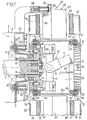
- Figure 1 shows part of a transmission motor vehicle, especially truck or bus.
- a casing 3 which comprises on the one hand a main body 4 and on the other hand a front closing plate 5.
- the closing plate 5 has no part support specially designed for mounting the retarder electric, and more generally, it is designed regardless of whether or not the retarder is present electric.
- This closure plate 5 is fixed so waterproof on the main body 4 of the casing by means of screws 6 which pass through holes 7 made in said plate closure and which are screwed into the main body 4.
- the closing plate 5 is arranged in a plane general perpendicular to the X axis and it has a nose annular center 5a which projects outwards. This central nose 5a is crossed by the output shaft 2, and it also receives the sleeve 13 of the fork 12.
- the output shaft 2 is supported by an end bearing constituted by a bearing 8 which is standard and which is dimensioned regardless of whether or not the retarder is present electric 20.
- this comprises, in a manner known per se, an induced rotor 21 which rotates with the shaft 2 and an inductor stator 22 fixed comprising electromagnetic coils 23 which, when are traversed by an electric current, generate eddy currents in rotor 21, so that this rotor exerts braking torque on the shaft 2.
- the stator coils 23 are of even number, and they each have a ferromagnetic core (not shown) which extends longitudinally parallel to the X axis between two poles 24.
- the set of poles 24 forms two rings centered on the X axis, the poles 24 of each crown being alternately oriented North and South.
- the coils 23 and their cores are carried by a rigid flange 25 made of non-magnetic material, which has a substantially annular shape and which is itself fixed by screws 26 with four arms 28 of a frame 27.
- Frame 27 which is clearly visible in the figures 1 and 2, is a rigid part which can be produced by example in GS type cast iron with holes 29 in correspondence with the holes 7 of the closure plate.
- support surfaces are machined 30 annular, perfectly flat and perfectly perpendicular to the X axis, on the outside of the plate closure 5 around each hole 7, and the frame 27 likewise has machined bearing surfaces 31 perfectly flat and perfectly perpendicular to the axis X.
- the bearing surfaces 30 and 31 are arranged in correspondence and are in mutual contact, allowing a good support of the frame 27 on the closing plate 5.
- the rotor 21 which is clearly visible on Figures 1 and 3, includes two wheels 32 which are arranged each in a radial plane and which are made in ferromagnetic material, usually steel.
- Each of the wheels 32 has an annular disc 33 relatively thick which is arranged facing one of the crowns of stator poles 24, a thin air gap (for example from 1 to 3 mm) being left free between this disc 33 and the corresponding poles 24.
- Each disc 33 is integral with a crown vanes 34 forming cooling fins, which all extend in the radial plane of the corresponding wheel 32.
- these blades each extend in a radial direction, but they could eventually extend each in a direction inclined to the radial direction, everything remaining in the radial plane of their wheel 32.
- each wheel 32 On the face of each wheel 32 which is the most away from the stator, the blades 34 are further braced by a relatively thin annular disc 35.
- This disc 35 thus delimits with the thick disc 33 an annular space in which the blades 34 are arranged and into which the cooling air of the wheels 32.
- each wheel 32 of the rotor is mounted at an axial end of an intermediate steel tube 36 which has a generally cylindrical shape of revolution centered on the X axis.
- each wheel 32 of the rotor comprises four fixing arms 37 which are arranged at 90 degrees from each other and which each consist of two blades 34 extended inward to one fixing plate 38 itself fixed to the intermediate tube 36 by a screw 39 parallel to the X axis.
- each fixing arm 37 the two vanes 34 which form each fixing arm 37 are separated from each other by a non-prolonged blading 34 radially inward, but this arrangement is not not limiting.
- the fixing arms 37 extend in the plane radial of their wheel 32, without extending at an axial angle towards the median plane of the retarder, as was the case in the electrical retarders of the prior art: there this results in greater ease of production of the wheels 32, especially when these wheels are obtained by molding.
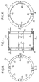
- the intermediate tube 36 which is shown in detail in Figures 4 to 6, present at its two axial ends of the first and second flanges substantially annular, respectively 40, 41, in which are screwed the screws 39 for fixing the wheels 32.
- the screws 39 pass through steel rings 42 which are each force fitted both in a bore 43 belonging to the plate 38 corresponding, and in a bore 44 belonging to the flange 40, 41 corresponding.
- the intermediate tube 36 includes preferably slots 45 which extend axially towards inside the tube from either of the two ends of this tube, each slot 45 extending over less of half the axial length of the tube, for example on about 1/3 of the length of the tube.
- the slots 45 are arranged in pairs by framing each screw 39, and thus delimiting at the two ends of the tube 36 of the axial blades 46 at the ends of which are fixed the arms 37 of the wheels 32.
- the metal blades 46 are dimensioned to be able to deform elastically radially towards outside when the rotor wheels 32 are subjected to thermal expansion due to high temperatures to which they can be worn during operation of the retarder, which compensates for the absence of deformability radial of the fixing arms 37.
- the fixing arms 37 could moreover possibly be designed to be able to deform radially. This deformability can be obtained for example by giving a sufficient curvature to the extensions vanes 34 which constitute the fixing arms 37, which fixing arms preferably remain located in the radial plane of their wheel 32.
- the blades 34 which extend radially inward to form the arms of attachment 37 preferably each have a narrowing 47 along the direction of the X axis, between the disc 33 and the corresponding plate 38.
- This narrowing 47 makes it possible to reduce the rigidity arms 37 in flexion, which limits the stresses due thermal deformations of the parts.
- first flange 40 of the intermediate tube 36 is fixed to a steel plate 49 by four screws 48, angularly offset 45 degrees from screws 39.
- This plate 49 is located substantially in the same radial plane as the plates 38 for fixing the wheels 32, and it has external notches 50 to let the passage to said plates 38.
- the plate 49 is fixed by means of screws 51 on the rear face 12a of the fork 12 of the universal joint, in a free annular space between the fork 12 and the plate closing 5.
- the rear face 12a is formed by a shoulder exterior presented by the fork 12, and this rear face is preferably machined to be perfectly flat and perfectly perpendicular to the X axis.
- the screws 51 are advantageously supplemented by nested metal dowels 52 by force both in a bore 53 which passes axially the plate 49 and in a blind bore 54 which enters the fork 12 from its rear face 12a (see figure 3A).
- the central part 36a of this intermediate tube which is axially between the two flanges 40, 41, can be located radially very close to the coils 23, since the fixing arms 37 of the two wheels 32 do not not join at the center of the coil crowns 23, unlike the devices of the prior art.
- this central part 36a of the tube midsole must support only one wheel 32 and not two, this central part can be relatively thin and present for example a thickness of the order of 6 mm.
- the flanges 40, 41 of the intermediate tube 36 are arranged radially inward of the part central 36a of this tube, so that the intermediate tube has substantially no protruding part towards the exterior, which allows both an introduction easy of the intermediate tube 36 inside the crown of coils 23 despite the small radial clearance between this game and this crown, and secondly to limit the space radial of the intermediate tube.
- the second flange 41 of this tube insert towards the inside of the notches 55 in its intermediate portions between the deformable blades 46.
- the device which has just been described can be entirely made in the factory during the initial assembly of the transmission but it can also be achieved by retrofitting of the electric retarder on a transmission already mounted in a vehicle.
- ankles are preferably provided of metal which are arranged next to at least some screws 39 and which are force-fitted both into the corresponding plate 38 and in the flange 40, 41 corresponding.
Landscapes
- Engineering & Computer Science (AREA)
- General Engineering & Computer Science (AREA)
- Power Engineering (AREA)
- Mechanical Engineering (AREA)
- Dynamo-Electric Clutches, Dynamo-Electric Brakes (AREA)
- Electric Propulsion And Braking For Vehicles (AREA)
- Braking Arrangements (AREA)
- Connection Of Motors, Electrical Generators, Mechanical Devices, And The Like (AREA)
- Motor Power Transmission Devices (AREA)
- Arrangement Or Mounting Of Propulsion Units For Vehicles (AREA)
- Braking Systems And Boosters (AREA)
Claims (10)
- Kraftübertragung für Motor-Landfahrzeuge, umfassend:dadurch gekennzeichnet, daß die Kardangelenkgabel (12) direkt an der Ausgangswelle (2) befestigt ist,einen Kraftübertragungsmechanismus (1), der durch den Motor des Fahrzeugs angetrieben wird und eine um eine Achse (X) drehende Ausgangswelle (2) aufweist, wobei dieser Mechanismus ein Gehäuse (3) enthält, das seinerseits einen Hauptkörper (4) umfaßt, an dem eine Schließplatte (5) mittels Schrauben (6) befestigt ist, wobei sich diese Schließplatte in einer Mittelebene erstreckt, die senkrecht zur Drehachse ist, und die Ausgangswelle durch wenigstens ein Endlager (8) in der Nähe der Schließplatte abgestützt wird,eine Kardangelenkgabel (12), die von der Ausgangswelle (2) des Kraftübertragungsmechanismus durch die Schließplatte (5) hindurch angetrieben wird und die ihrerseits eine Verbindungswelle (11) antreibt, wobei diese Kardangelenkgabel wenigstens eine äußere Schulter aufweist, die eine rückseitige Fläche (12a) bildet, die zur Schließplatte (5) hin ausgerichtet ist, wobei die rückseitige Fläche axial zur Schließplatte entfernt liegt, indem einiger ringförmiger Raum zwischen ihr selbst und der Schließplatte frei gelassen wird,und eine elektrische Wirbelstrombremse (20), die einerseits einen ringförmigen Induktorstator (22), der vorstehend am Gehäuse (3) mit Hilfe eines Tragwerks (27) angebracht ist, und andererseits einen Rotor (21) enthält, der wenigstens eine Läuferscheibe (33) aus ferromagnetischem Material umfaßt, die gegenüberstehend zum Stator angeordnet ist und die an der Ausgangswelle (2) des Kraftübertragungsmechanismus mittels eines Stützorgans (49) befestigt ist, wobei das Tragwerk (27) am Gehäuse (3) durch wenigstens einige der vorher erwähnten Schrauben (6) befestigt ist, die auch zur Befestigung der Schließplatte (5) dieses Gehäuses dienen, wobei diese Schließplatte von diesen Schrauben durchlaufen wird und somit zwischen dem Tragwerk (27) und dem Hauptkörper (4) des Gehäuses eingeklemmt ist, wobei die Schließplatte keinerlei speziell zum Anbringen des Stators der elektrischen Bremse ausgelegtes Stützorgan einschließt,
daß das Stützorgan (49) des Rotors einzig und allein an der rückseitigen Fläche (12a) der Kardangelenkgabel (12) im zwischen der Schließplatte und der rückseitigen Fläche der Kardangelenkgabel liegenden ringförmigen Raum befestigt ist, wobei diese Kardangelenkgabel eine vom Vorhandensein der elektrischen Bremse unabhängige axiale Position hat,
und daß das Endlager (8) der Ausgangswelle eine vom Vorhandensein der elektrischen Bremse unabhängige Beschaffenheit hat. - Kraftübertragung nach Anspruch 1, bei der das Stützorgan (49) an der rückseitigen Fläche (12a) der Kardangelenkgabel verschraubt ist.
- Kraftübertragung nach Anspruch 2, bei der die Kardangelenkgabel (12) wenigstens eine Blindbohrung (54) enthält, die in ihre rückseitige Fläche (12a) mündet, wobei das Stützorgan (49) von einer Bohrung (53) in genauer Übereinstimmung mit der Bohrung (54) der Kardangelenkgabel durchlaufen wird und ein Metallbolzen (52) mit Kraft in diese beiden Bohrungen hineingetrieben ist, um das Stützorgan und die Kardangelenkgabel drehungsmäßig vollkommen zu verbinden.
- Kraftübertragung nach einem der vorhergehenden Ansprüche, bei der das Stützorgan (49) eine im wesentlichen ringförmige Scheibe ist, die sich, ausgehend von der Kardangelenkgabel (12), radial nach außen erstreckt.
- Kraftübertragung nach Anspruch 4, bei der die Scheibe (49) mit einem Rohr (36) vereint ist, das die Kardangelenkgabel (12) umgibt und an dem die Läuferscheibe (33) des Rotors angebracht ist.
- Kraftübertragung nach einem der vorhergehenden Ansprüche, bei der der Kraftübertragungsmechanismus (1) ein Schaltgetriebe ist.
- Verfahren zum Anbringen einer elektrischen Wirbelstrombremse (20) an einer Kraftübertragung für Motor-Landfahrzeuge, wobei diese Kraftübertragung umfaßt:wobei die Ausgangswelle durch wenigstens ein Endlager (8) in der Nähe der Schließplatte abgestützt ist, wobei das Endlager eine vom Vorhandensein der elektrischen Bremse unabhängige Beschaffenheit hat,einen Kraftübertragungsmechanismus (1), der durch den Motor des Fahrzeugs angetrieben wird und eine um eine Achse (X) drehende Ausgangswelle (2) aufweist, wobei dieser Mechanismus ein Gehäuse (3) enthält, das seinerseits einen Hauptkörper (4) umfaßt, an dem eine Schließplatte (5) mittels Schrauben (6) befestigt ist, wobei sich diese Schließplatte in einer Mittelebene erstreckt, die senkrecht zur Drehachse (X) ist und die Schließplatte keinerlei speziell zum Anbringen der elektrischen Bremse ausgelegtes Stützorgan enthält,wobei die elektrische Wirbelstrombremse (20) einerseits einen ringförmigen Induktorstator (22), der mit Hilfe eines Tragwerks (27) vorstehend am Gehäuse (3) angebracht werden soll, und andererseits einen Rotor (21) enthält, der wenigstens eine Läuferscheibe (33) aus ferromagnetischem Material umfaßt, die gegenüberstehend zum Stator angebracht ist und die an der Kardangelenkgabel (12) mittels eines Stützorgans (49) befestigt werden soll,und eine Kardangelenkgabel (12), die direkt an der Ausgangswelle (2) des Kraftübertragungsmechanismus durch die Schließplatte (5) hindurch befestigt ist und die eine Verbindungswelle (11) antreibt, wobei diese Kardangelenkgabel wenigstens eine äußere Schulter aufweist, die eine rückseitige Fläche (12a) bildet, die zur Schließplatte hin ausgerichtet ist, wobei die rückseitige Fläche axial zur Schließplatte entfernt liegt, indem einiger ringförmiger Raum zwischen ihr selbst und der Schließplatte frei gelassen wird, und die Kardangelenkgabel (12) eine vom Vorhandensein der elektrischen Bremse unabhängige axiale Position hat,
wobei dieses Verfahren die folgenden Schritte umfaßt:a) Ausbauen der Kardangelenkgabel (12),b) Befestigen des Tragwerks (27) am Gehäuse (3) durch wenigstens einige Schrauben (6) der Schließplatte (5) unter gleichzeitigem Befestigen dieser Schließplatte, wobei die Schließplatte (5) dann von diesen Schrauben (6) durchlaufen wird und somit zwischen dem Tragwerk (27) und dem Hauptkörper (4) des Gehäuses eingeklemmt ist,c) Befestigen des Stützorgans (49) des Rotors einzig und allein an der rückseitigen Fläche (12a) der Kardangelenkgabel im zwischen der Schließplatte (5) und der rückseitigen Fläche (12a) der Kardangelenkgabel liegenden, ringförmigen Raum,d) und Wiederanbringen dieser Kardangelenkgabel in der genauen axialen Position, die sie anfänglich relativ zur Schließplatte (5) belegte. - Verfahren nach Anspruch 7, das außerdem einen vorbereitenden Schritt umfaßt, im Verlaufe dessen :auf der Außenfläche der Schließplatte (5) vollkommen ebene und zur Drehachse (X) vollkommen senkrechte Abstützflächen (30) um Befestigungslöcher (7) der Schließplatte gefertigt werden, welche die Schrauben (6) zur Befestigung dieser Platte aufnehmen, wobei das Tragwerk (27) überdies komplementäre Abstützflächen (31) enthält, die gegenüberstehend zu den Abstützflächen der Schließplatte zu liegen kommen,und die rückseitige Fläche (12a) der Kardangelenkgabel derart gefertigt wird, daß sie vollkommen eben und senkrecht zur Drehachse (X) ist.
- Verfahren nach einem der Ansprüche 7 und 8, bei dem dem Schritt c) ein Schritt nachfolgt, der darin besteht:zugleich in das Befestigungsorgan (49) und in die Kardangelenkgabel (12) wenigstens eine Bohrung (53, 54) zu bohren, die durch das Stützorgan (49) hindurchläuft und in die Kardangelenkgabel (12) eindringt,und mit Kraft einen Metallbolzen (52) in die genannte Bohrung hineinzutreiben, wobei dieser Bolzen zugleich in das Stützorgan und in die Kardangelenkgabel eindringt.
- Verfahren nach einem der Ansprüche 7 bis 9, bei dem im Verlaufe des Schrittes a) wenigstens einige der Befestigungsschrauben der Schließplatte (5) entfernt und diese durch längere Schrauben (6) ersetzt werden, wobei gleichzeitig das Tragwerk (27) am Gehäuse (3) mittels dieser Schrauben befestigt wird.
Applications Claiming Priority (2)
| Application Number | Priority Date | Filing Date | Title |
|---|---|---|---|
| FR9601688A FR2744678B1 (fr) | 1996-02-12 | 1996-02-12 | Transmission de vehicule equipee d'un ralentisseur electrique |
| FR9601688 | 1996-02-12 |
Publications (2)
| Publication Number | Publication Date |
|---|---|
| EP0789444A1 EP0789444A1 (de) | 1997-08-13 |
| EP0789444B1 true EP0789444B1 (de) | 2001-12-19 |
Family
ID=9489085
Family Applications (1)
| Application Number | Title | Priority Date | Filing Date |
|---|---|---|---|
| EP97400281A Expired - Lifetime EP0789444B1 (de) | 1996-02-12 | 1997-02-07 | Kraftfahrzeuggetriebe, versehen mit einem elektrischen Retarder |
Country Status (9)
| Country | Link |
|---|---|
| US (1) | US5838084A (de) |
| EP (1) | EP0789444B1 (de) |
| JP (1) | JPH09309348A (de) |
| KR (1) | KR970062421A (de) |
| AT (1) | ATE211321T1 (de) |
| CA (1) | CA2197163A1 (de) |
| DE (1) | DE69709198T2 (de) |
| ES (1) | ES2169326T3 (de) |
| FR (1) | FR2744678B1 (de) |
Families Citing this family (2)
| Publication number | Priority date | Publication date | Assignee | Title |
|---|---|---|---|---|
| DE102010051715A1 (de) * | 2010-11-19 | 2012-05-24 | Voith Patent Gmbh | Antriebsstrang mit einem hydrodynamischen Retarder |
| RU2473166C1 (ru) * | 2011-11-21 | 2013-01-20 | Федеральное государственное унитарное предприятие "Научно-производственное предприятие "Исток" (ФГУП НПП "Исток") | Смеситель свч |
Family Cites Families (3)
| Publication number | Priority date | Publication date | Assignee | Title |
|---|---|---|---|---|
| FR2247846B1 (de) * | 1973-10-15 | 1980-05-09 | Labavia | |
| ES453792A1 (es) * | 1976-11-30 | 1977-11-01 | Lafuente Ruberte Antonio | Perfeccionamientos introducidos en la construccion de ralen-tizadores para vehiculos. |
| FR2529030B1 (fr) * | 1982-06-17 | 1985-09-27 | Labavia | Perfectionnements aux ralentisseurs electriques |
-
1996
- 1996-02-12 FR FR9601688A patent/FR2744678B1/fr not_active Expired - Fee Related
-
1997
- 1997-02-07 ES ES97400281T patent/ES2169326T3/es not_active Expired - Lifetime
- 1997-02-07 DE DE69709198T patent/DE69709198T2/de not_active Expired - Fee Related
- 1997-02-07 AT AT97400281T patent/ATE211321T1/de not_active IP Right Cessation
- 1997-02-07 EP EP97400281A patent/EP0789444B1/de not_active Expired - Lifetime
- 1997-02-10 CA CA002197163A patent/CA2197163A1/fr not_active Abandoned
- 1997-02-11 US US08/802,336 patent/US5838084A/en not_active Expired - Fee Related
- 1997-02-12 JP JP9028190A patent/JPH09309348A/ja not_active Withdrawn
- 1997-02-12 KR KR1019970004087A patent/KR970062421A/ko not_active Withdrawn
Also Published As
| Publication number | Publication date |
|---|---|
| DE69709198T2 (de) | 2002-08-22 |
| EP0789444A1 (de) | 1997-08-13 |
| KR970062421A (ko) | 1997-09-12 |
| FR2744678B1 (fr) | 1998-04-10 |
| ATE211321T1 (de) | 2002-01-15 |
| FR2744678A1 (fr) | 1997-08-14 |
| US5838084A (en) | 1998-11-17 |
| ES2169326T3 (es) | 2002-07-01 |
| DE69709198D1 (de) | 2002-01-31 |
| CA2197163A1 (fr) | 1997-08-13 |
| JPH09309348A (ja) | 1997-12-02 |
Similar Documents
| Publication | Publication Date | Title |
|---|---|---|
| WO2011135199A1 (fr) | Assemblage instrumenté et rondelle frein associée | |
| CA2486735C (fr) | Atterrisseur, frein pour roue d'aeronef, ensemble de roue freinee d'aeronef, et procede de maintenance d'un tel atterrisseur | |
| FR2554883A1 (fr) | Systeme de palier pour le montage d'un arbre dans l'alesage d'un carter | |
| CH665316A5 (fr) | Ralentisseur electrique. | |
| FR2471517A1 (fr) | Dispositif de freinage et d'embrayage combine a commande electromagnetique | |
| EP0789443B1 (de) | Fahrzeuggetriebe versehen mit einem elektrischen Retarder | |
| EP0403714B1 (de) | Kraftfahrzeugantrieb mit elektrischen Bremsvorrichtungen | |
| EP0789442B1 (de) | Fahrzeuggetriebe versehen mit einem elektrischen Retarder | |
| EP0425338B1 (de) | Getriebe für Fahrzeuge mit elektrischer Bremsvorrichtung | |
| FR2529030A1 (fr) | Perfectionnements aux ralentisseurs electriques | |
| FR2957730A1 (fr) | Machine electrique tournante avec stator a bobinages concentriques | |
| EP0789444A1 (de) | Kraftfahrzeuggetriebe, versehen mit einem elektrischen Retarder | |
| EP0687055B1 (de) | Verbesserungen an Kraftfahrzeuggetrieben mit Wirbelstrombremse und an den Getriebebefestigungsteilen | |
| FR2742937A1 (fr) | Dispositif d'entrainement d'un vehicule | |
| EP1609234B1 (de) | Elektromagnetische fahrzeugbremse | |
| EP0406110B1 (de) | Antriebsübertragung für ein Kfz mit elektromagnetischen Bremsvorrichtungen | |
| FR2987185A1 (fr) | Systeme de fixation d'elements magnetiques dans une machine electrique a aimants permanents. | |
| EP0244307B1 (de) | Anker von elektromagnetischen Bremsvorrichtungen | |
| EP2584684A1 (de) | Auschauschbarer Stator einer elektromagnetischen Bremse und mit einem solchen Stator ausgestattete elektromagnetische Bremse | |
| EP1222731A1 (de) | Zwischen einem verbrennungsmotor und einem getriebe eingesetzte retarder-bremse | |
| FR2648881A1 (fr) | Joints de cardan court et transmission de vehicule equipee d'un tel joint et de preference d'un ralentisseur electrique | |
| WO2024235693A1 (fr) | Ensemble d'elements d'un groupe motopropulseur | |
| FR2860357A1 (fr) | Ralentisseur electromagnetique muni d'un dispositif de fixation | |
| FR2734672A1 (fr) | Rotor a inertie elevee | |
| FR2860355A1 (fr) | Ralentisseur electromagnetique muni d'une zone de degagement |
Legal Events
| Date | Code | Title | Description |
|---|---|---|---|
| PUAI | Public reference made under article 153(3) epc to a published international application that has entered the european phase |
Free format text: ORIGINAL CODE: 0009012 |
|
| AK | Designated contracting states |
Kind code of ref document: A1 Designated state(s): AT BE CH DE ES FR GB IT LI NL PT SE |
|
| 17P | Request for examination filed |
Effective date: 19970913 |
|
| 17Q | First examination report despatched |
Effective date: 19990506 |
|
| RAP1 | Party data changed (applicant data changed or rights of an application transferred) |
Owner name: LABINAL |
|
| GRAG | Despatch of communication of intention to grant |
Free format text: ORIGINAL CODE: EPIDOS AGRA |
|
| GRAG | Despatch of communication of intention to grant |
Free format text: ORIGINAL CODE: EPIDOS AGRA |
|
| GRAH | Despatch of communication of intention to grant a patent |
Free format text: ORIGINAL CODE: EPIDOS IGRA |
|
| GRAH | Despatch of communication of intention to grant a patent |
Free format text: ORIGINAL CODE: EPIDOS IGRA |
|
| GRAA | (expected) grant |
Free format text: ORIGINAL CODE: 0009210 |
|
| AK | Designated contracting states |
Kind code of ref document: B1 Designated state(s): AT BE CH DE ES FR GB IT LI NL PT SE |
|
| PG25 | Lapsed in a contracting state [announced via postgrant information from national office to epo] |
Ref country code: NL Free format text: LAPSE BECAUSE OF FAILURE TO SUBMIT A TRANSLATION OF THE DESCRIPTION OR TO PAY THE FEE WITHIN THE PRESCRIBED TIME-LIMIT Effective date: 20011219 Ref country code: IT Free format text: LAPSE BECAUSE OF FAILURE TO SUBMIT A TRANSLATION OF THE DESCRIPTION OR TO PAY THE FEE WITHIN THE PRESCRIBED TIME-LIMIT;WARNING: LAPSES OF ITALIAN PATENTS WITH EFFECTIVE DATE BEFORE 2007 MAY HAVE OCCURRED AT ANY TIME BEFORE 2007. THE CORRECT EFFECTIVE DATE MAY BE DIFFERENT FROM THE ONE RECORDED. Effective date: 20011219 Ref country code: GB Free format text: LAPSE BECAUSE OF FAILURE TO SUBMIT A TRANSLATION OF THE DESCRIPTION OR TO PAY THE FEE WITHIN THE PRESCRIBED TIME-LIMIT Effective date: 20011219 Ref country code: AT Free format text: LAPSE BECAUSE OF FAILURE TO SUBMIT A TRANSLATION OF THE DESCRIPTION OR TO PAY THE FEE WITHIN THE PRESCRIBED TIME-LIMIT Effective date: 20011219 |
|
| REF | Corresponds to: |
Ref document number: 211321 Country of ref document: AT Date of ref document: 20020115 Kind code of ref document: T |
|
| REG | Reference to a national code |
Ref country code: CH Ref legal event code: EP |
|
| REG | Reference to a national code |
Ref country code: GB Ref legal event code: IF02 |
|
| REF | Corresponds to: |
Ref document number: 69709198 Country of ref document: DE Date of ref document: 20020131 |
|
| PG25 | Lapsed in a contracting state [announced via postgrant information from national office to epo] |
Ref country code: LI Free format text: LAPSE BECAUSE OF NON-PAYMENT OF DUE FEES Effective date: 20020228 Ref country code: CH Free format text: LAPSE BECAUSE OF NON-PAYMENT OF DUE FEES Effective date: 20020228 Ref country code: BE Free format text: LAPSE BECAUSE OF NON-PAYMENT OF DUE FEES Effective date: 20020228 |
|
| PG25 | Lapsed in a contracting state [announced via postgrant information from national office to epo] |
Ref country code: SE Free format text: LAPSE BECAUSE OF FAILURE TO SUBMIT A TRANSLATION OF THE DESCRIPTION OR TO PAY THE FEE WITHIN THE PRESCRIBED TIME-LIMIT Effective date: 20020319 Ref country code: PT Free format text: LAPSE BECAUSE OF FAILURE TO SUBMIT A TRANSLATION OF THE DESCRIPTION OR TO PAY THE FEE WITHIN THE PRESCRIBED TIME-LIMIT Effective date: 20020319 |
|
| NLV1 | Nl: lapsed or annulled due to failure to fulfill the requirements of art. 29p and 29m of the patents act | ||
| GBV | Gb: ep patent (uk) treated as always having been void in accordance with gb section 77(7)/1977 [no translation filed] |
Effective date: 20011219 |
|
| REG | Reference to a national code |
Ref country code: ES Ref legal event code: FG2A Ref document number: 2169326 Country of ref document: ES Kind code of ref document: T3 |
|
| BERE | Be: lapsed |
Owner name: LABINAL Effective date: 20020228 |
|
| REG | Reference to a national code |
Ref country code: CH Ref legal event code: PL |
|
| PLBE | No opposition filed within time limit |
Free format text: ORIGINAL CODE: 0009261 |
|
| STAA | Information on the status of an ep patent application or granted ep patent |
Free format text: STATUS: NO OPPOSITION FILED WITHIN TIME LIMIT |
|
| REG | Reference to a national code |
Ref country code: FR Ref legal event code: TP |
|
| 26N | No opposition filed | ||
| NLV1 | Nl: lapsed or annulled due to failure to fulfill the requirements of art. 29p and 29m of the patents act | ||
| PGFP | Annual fee paid to national office [announced via postgrant information from national office to epo] |
Ref country code: ES Payment date: 20090220 Year of fee payment: 13 |
|
| PGFP | Annual fee paid to national office [announced via postgrant information from national office to epo] |
Ref country code: DE Payment date: 20090211 Year of fee payment: 13 |
|
| PGFP | Annual fee paid to national office [announced via postgrant information from national office to epo] |
Ref country code: FR Payment date: 20090227 Year of fee payment: 13 |
|
| REG | Reference to a national code |
Ref country code: FR Ref legal event code: ST Effective date: 20101029 |
|
| PG25 | Lapsed in a contracting state [announced via postgrant information from national office to epo] |
Ref country code: FR Free format text: LAPSE BECAUSE OF NON-PAYMENT OF DUE FEES Effective date: 20100301 |
|
| PG25 | Lapsed in a contracting state [announced via postgrant information from national office to epo] |
Ref country code: DE Free format text: LAPSE BECAUSE OF NON-PAYMENT OF DUE FEES Effective date: 20100901 |
|
| REG | Reference to a national code |
Ref country code: ES Ref legal event code: FD2A Effective date: 20110308 |
|
| PG25 | Lapsed in a contracting state [announced via postgrant information from national office to epo] |
Ref country code: ES Free format text: LAPSE BECAUSE OF NON-PAYMENT OF DUE FEES Effective date: 20110307 |
|
| PG25 | Lapsed in a contracting state [announced via postgrant information from national office to epo] |
Ref country code: ES Free format text: LAPSE BECAUSE OF NON-PAYMENT OF DUE FEES Effective date: 20100208 |