EP0789991A1 - Umhüllmaschine für Ballen - Google Patents
Umhüllmaschine für Ballen Download PDFInfo
- Publication number
- EP0789991A1 EP0789991A1 EP97200276A EP97200276A EP0789991A1 EP 0789991 A1 EP0789991 A1 EP 0789991A1 EP 97200276 A EP97200276 A EP 97200276A EP 97200276 A EP97200276 A EP 97200276A EP 0789991 A1 EP0789991 A1 EP 0789991A1
- Authority
- EP
- European Patent Office
- Prior art keywords
- container
- machine
- wrapping
- bale
- bales
- Prior art date
- Legal status (The legal status is an assumption and is not a legal conclusion. Google has not performed a legal analysis and makes no representation as to the accuracy of the status listed.)
- Granted
Links
Images

Classifications
-
- A—HUMAN NECESSITIES
- A01—AGRICULTURE; FORESTRY; ANIMAL HUSBANDRY; HUNTING; TRAPPING; FISHING
- A01F—PROCESSING OF HARVESTED PRODUCE; HAY OR STRAW PRESSES; DEVICES FOR STORING AGRICULTURAL OR HORTICULTURAL PRODUCE
- A01F25/00—Storing agricultural or horticultural produce; Hanging-up harvested fruit
- A01F25/14—Containers specially adapted for storing
-
- A—HUMAN NECESSITIES
- A01—AGRICULTURE; FORESTRY; ANIMAL HUSBANDRY; HUNTING; TRAPPING; FISHING
- A01F—PROCESSING OF HARVESTED PRODUCE; HAY OR STRAW PRESSES; DEVICES FOR STORING AGRICULTURAL OR HORTICULTURAL PRODUCE
- A01F15/00—Baling presses for straw, hay or the like
- A01F15/005—Baling presses for straw, hay or the like for conditioning bales, e.g. rebaling
Definitions
- the present invention relates to a machine for wrapping bales, such as grass, straw or hay bales.
- Such machines are known, e.g. in the form of machines wrapping plastic sheet around a bale. These machines have the disadvantage that the packing applied is vulnerable and environment-unfriendly.
- the present invention aims at obtaining a machine in which such drawbacks are at least limited to a considerable extent. According to the invention, this is achieved by means of a construction in which the machine is provided with means for placing a bale into a container.
- a suchlike machine has the advantages that wrapping of bales can eventually be executed more cheaply, that wrapped bales are transportable without running the risk of being easily damaged during transport and that the logistical handling of wrapped bales is optimal.
- the invention also relates to a method of storing bales, such as grass, straw or hay bales, in which method the bales are picked up from the ground during driving by means of a self-driving machine at the front thereof or near thereto, are automatically wrapped in the machine and are subsequently laid down on the field during driving at the back of the machine or near thereto.
- This has the advantage that bales are protected in a quick manner against the weather and animals, without expensive storage space or time-consuming collecting of the bales being required.
- the invention relates to a method in which, by means of a self-driving machine, bales are picked up from the field during driving, are wrapped in the machine during driving and are laid down on the field during driving, whereby stocks of wrapping elements are transported in the machine and are taken out of the stack during driving by means of an unstacking device and are displaced into a wrapping space for the purpose of wrapping a bale.
- the invention further relates to a bale container, consisting of at least one reusable wrapping part, made of substantially solid material.
- a bale container consisting of at least one reusable wrapping part, made of substantially solid material.
- Such a container may consist e.g. of a bottom part, covered with either solid or non-solid material and an either reusable or non-reusable cover part.
- the bottom part of a container comprises transversely provided openings suitable to include the forks of a so-called forklift. This has the advantage of a simple handling while the risk of damage of the container is rather small.
- the machine according to the present invention has the additional advantage that positioning of a bale on a bottom part or in a container or a part thereof can be realized in a controllable manner.
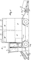
- FIG 1 shows in side view the wrapping machine according to the invention, which wrapping machine, in the present embodiment, is a self-driving one.
- the machine is particularly suitable for picking up and wrapping bales of crop, such as straw or hay, lying on the field. More in particular the machine is attuned to rectangular bales.
- the machine is provided with wheels 2, a driver's cabin 6, a pick-up element 3 on which in the figure a bale 4 is drawn, a processing space 5 and a discharge member 7, on which in the figure there is drawn a wrapping 8, more specifically to be designated as a container 8.
- the container 8 comprises at least one part made of solid material, which part may be covered with or be disposed on a second part, which may be made of a solid material as well as of a flexible material, and may be constituted e.g. by a case fitting to the first part so as to close same off.
- a container 8 consists of a bottom part 9 and a cover part 10.
- an intermediate part constituted by a wall surrounding the bale and fitting to the bottom part 9.
- Both the pick-up member 3 and the discharge member 7 are connected freely pivotably with the machine during operation and are provided with a pair of supporting wheels 12, 13 respectively for the purpose of following the ground.
- the supporting wheels 12, 13 may also be disposed near the free end of the pick-up member 3, respectively the discharge member 7, and may be designed so as to be pivotable. With the aid of a non-shown operating element the pick-up member 3 and the discharge member 7 can be pivoted into a substantially upwardly directed transport position.
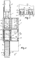
- FIG 2 is a cross-section according to the line II - II in Figure 1 and shows, in line with the pick-up member 3, a passage and wrapping space 16 and a passage 19 which constitutes at the same time a finishing space.
- a bale 4 wrapped in a container 8.
- the machine At its rear side the machine comprises a discharge member 7 which is connected to the passage. Because of this, in the process of picking up, processing and discharging, a bale 4 can be guided in a straight line through the machine.
- Above the wrapping space 16 there is available in the processing space 5 a stacking space 44 including a first stack 17 of cover parts 10. Via gripping members 29 the stack 17 is kept at a small level above a container 8 possibly present in the wrapping space 16.
- the gripping members 29 are movable along vertically extending guide means 33, 35, arranged at the side of the wrapping space 16 and designed in the present embodiment as a T-profile.
- the gripping members 29 comprise an electromagnetically controllable gripping element 30, here constituted by a stop pin, by means of which a gripping member 29 can seize a cover part 10. To that end the cover parts 10 are provided with fitting recesses 11. Under automatic control the gripping members 29 are movable upwards and downwards along the guide means 33, 35. In the present embodiment, this is realized in a non-shown manner with the aid of hydraulic control elements disposed in the machine, which control elements, via a flexible connecting element such as a cable, are connected with a gripping member 29.
- such a movability can be realized by means of an electronic or pneumatic control unit or motor, either or not engaging directly the gripping member 29 or closely driving the roller 32 thereof, while moving the gripping member 29, either or not via e.g. a gear rack mechanism, upwards and downwards along a guide means 33, 35.
- a driven continuous transport element 26 In the wrapping space 16, which is sufficiently large for surrounding a container 8, at some height above the bottom of the wrapping space 16, but substantially within the height of a bale 4 placed on a bottom part 9, along the upright longitudinal sides of said space, there is furthermore arranged a driven continuous transport element 26.
- the transport elements 26 are pivotable into and out of an operative position via parallelogram arms 27 engaged in the present embodiment by a non-shown control element, in this case a hydraulic cylinder. In their operative position the transport elements 26 are pivoted in such a way that, at least with a foremost part, they abut against an upright side wall of a bale 4 supplied by the pick-up element 3.
- the continuous transport elements 26 are suitable to engage the side walls of a bale 4, such that the latter, after having been moved upwards by the pick-up member 3, can be engaged by the continuous transport elements 26 together in order to be displaced further in the wrapping space 16.
- a bale 4, released by pivoting out of the operative position of the transport elements 26, gets into the wrapping space 16 on a bottom part 9 which, via a pair of motor-driven continuous conveyors 20, is supplied from a stacking space 28 for a stack of bottom parts 18, which stacking space 28 is available in the processing space 5 next to the wrapping space 16.
- the height of the stacking space 28 corresponds to the height of the processing space 5, and consequently to the collective height of the wrapping space 16 and the stacking space 44 for the stack of cover parts 17.
- the volume of a stacking space for cover parts 10 or bottom parts 9 corresponds to the volume of a cover or bottom part increased by the room required for the gripping members 29 arranged at a side of the elements.
- the stacking space 28 is provided, in an equal manner, with gripping members 29 and with identical guide means 36 which, however, are shorter here, while the guide means 35 is used in the stacking space 28 together with the gripping members 29.
- the bottom of the wrapping space 16 is constituted by a pair of driven continuous transport elements 21, orientated in longitudinal direction, and of a pair of identical transport elements 20 which, however, are orientated transversely and extend into the adjacent stacking space 28.
- the bottom of the finishing space 19 is constituted by an identical pair of transport elements 22, orientated in longitudinal direction and extending partially into the wrapping space 16.
- the passages 16, 19 are confined at their upper sides by stacking spaces 44, 45 respectively for cover parts 10.
- Above the wrapping space 16 there is provided a first stack of cover parts 17 and above the finishing space 19, in the stacking space 45, there is available a second stack of cover parts 17.
- Behind the stacking space 28 the processing space 5 comprises a space 47 which, in a specific embodiment, is used as a buffer space for wrappings 8 to be discharged.
- a stack 17 comprises ten cover parts 10, while the stack 18 comprises thirty bottom parts 9.
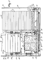
- FIG 3 is a plan view according to the arrow III in Figure 1 and shows a motor 11, in this case designed as a hydraulic motor, of the pick-up member 3.
- Said motor 11 serves for driving a continuous transport element 14, here constituted by a rubber conveyor.
- the transport element 14 is provided with short projections which, by hooking on, facilitate the picking-up of a bale 4 from the ground.
- the bottom of the stacking space 45, 46 is constituted by motor-driven continuous transport elements 23, which are disposed transversely and reach into the space for the second stack 17.
- the bottom of the stacking space 46 also comprises a pair of identical transport elements 24, which are however orientated in the longitudinal direction of the machine, for transporting a stack of cover parts 17 to the stacking space 44 above the wrapping space 16.
- the discharge member 7 is constituted by a guide chute.
- the discharge member 7 may be provided with a stop element 37, by means of which a container 8 is kept in the machine until a next container 8 is about to be passed to the discharge member 7.
- the stop element 37 By using the stop element 37 the containers 8 can be laid down on the ground in pairs in the vicinity of each other.
- Figure 4 shows in a cross-section taken on the line IV - IV in Figure 2 the above-described transverse and longitudinal transport elements 23 and 24. Therebelow, in line with the bottom of the wrapping space 16, there is disposed the pair of transport elements 22 for the discharge of a container 8.
- the guide means 38 are pivotable in downward direction into a vertical position about a pivot shaft orientated in the direction of travel A.
- at least one of at least one pair of guide means 38 preferably that in the middle, is designed as a motor-driven one.
- FIG. 5 shows in detail in side view according to the cross-section V - V in Figure 2 a possible design of a gripping member 29.
- the gripping member 29 comprises a U-profile 31, in the basic part of which there is provided an aperture through which the pin of the electromagnetic gripping element 30 is movable.
- the element 30 is fastened to the basic part of the U-profile.
- a guide strip of a guide means 33 arranged between the rollers of a pair of rollers 32, a guide strip of a guide means 33, designed as a T-profile and connected in the figure with the wall 34 of the processing space 5, extends vertically and parallel to the wall of the processing space 5.
- the element 30 may be provided at the height of the rollers 32 so as to extend partly therebetween against the base of the U-profile.
- the element 30 may also be provided at some distance under the rollers 32 against a projection of the base.
- the machine is provided at different places with sensors, such as light sensitive sensors, by means of which the interruption of a beam of light is detected.
- sensors are also meant e.g. mechanical and electromechanical detectors or electromechanical switches.
- the sensors insofar as they are not designed as mechanical ones, are included in a control system, here designed as an electronic one, for controlling and co-ordinating of the wrapping device, the pick-up member 3 and the discharge member 7 of the machine, described for the greater part in the foregoing, and the supply of stacks of wrapping parts 17.
- the control system comprises an electronically operated hydraulic sequence switch system for activating groups of gripping members 29 constituting together an unstacking device.
- the wrapping device mentioned comprises at least the transport elements 14, 20, 21, the gripping members 29 and the guide means 33, 35, i.e. the machine parts required, the positioning and the discharge of a bale 4, wrapping parts 9, 10, respectively a container 8, as well as possible connecting members for interconnecting the wrapping parts 9, 10.
- a bottom part 9 is produced substantially as a flat one, having in a specific embodiment a thickness or height of more than 10 cm. Moreover, in a specific embodiment, said bottom part is produced such that in the transverse direction there are slots for the forks of a so-called forklift.
- the dimensions of the width and the length of a bottom part 9 may be produced in dependence of the size of the bale, increased by a fitting edge suitable to fit to a cover part 10.
- the fitting edges are provided with a V-shaped groove which, for centring the cover part, cooperates with a V-shaped knife-like element at the bottom of an edge 25 of the cover part 10.
- a cover part 10 Near its upper end a cover part 10 has the size of the bale 4 to be wrapped and has also a height corresponding to that of the bale to be wrapped.
- the upright walls spread out somewhat in downward direction in order to allow the cover part to be disposed more easily.
- the edge 25 extends parallel to the fitting edge of a bottom part 9.
- the edge 25 comprises an upright edge portion at the outer circumference of the cover part.
- recesses 11 At the longitudinal sides of the cover part 10, in the upright edge portion near each corner, there are provided recesses 11 for the purpose of a possible engagement of the container part by means of stop pins 30.
- the edge 25 comprises, parallel to the lower edge portion and fitting to the upright edge portion, a second, horizontally extending edge portion which is connected with the upright wall of the cover and comprises at its upper side a V-shaped groove.
- the thus created box-like profile of the edge 25 confers an optimal sturdiness to the cover part, prevents stacked cover parts 10 from sticking to each other and offers a proper and durable possibility of engagement.
- a container 8, in particular the cover part 10 is suitable for wrapping up at least two bales 4.
- the first bale during its upward movement, will disappear at least partially in a lower cover part 10 of the stack 17.
- the first bale is let down thereon and, in the described manner, the stack of two bales is wrapped further.
- the wrapping parts 9 and 10 are made of such a material and the sealing of the container is such that a wrapped bale 4 is protected against the weather and animals, also when a container is left on the field without the parts thereof being interconnected.
- the machine moves in the direction of travel A in such a way that the pick-up member 3 is positioned in front of a bale 4 lying on the ground.
- the bale is picked up by the pick-up member 3 during driving of the machine and is transported in the direction of the wrapping space 16.
- the bale 4 is forced by a guide means constituting part of the pick-up member 3, e.g. an upright wall, in such a position that the longitudinal direction of the bale 4 and that of the machine correspond to each other.
- a sensor e.g.
- the transport elements 26 swing out inwardly to such an extent that they abut to the picked-up bale 4 and the latter is put in a more advanced position in the wrapping space.
- the bale 4 is conveyed by means of the transport elements 26 until it has arrived at the desired position, which is also automatically established by means of a sensor. After transport has been stopped by means of the elements 26, said elements are automatically pivoted back into their inoperative position, shown in the figures, and the bale 4 has reached its definite position on a bottom part 9 already present in the wrapping space 16. To that end the bottom part 9 is placed in an early stage in the wrapping space 16 by means of the transversely orientated conveyors 20.
- a bottom part 9 is separated from the stack 18 and placed on the conveyor 20 by means of two groups of four gripping members 29, whose movements are activated e.g. by an electronically or hydraulically operated sequence switch system.
- a first group of four gripping members 29 is thereby active in the lower range of the stack 18 and engages the bottom parts 9, near the corners thereof, in the recesses 11 provided in the upright longitudinal walls of the bottom part 9.
- a second group of four gripping members 29 engages recesses 11 provided closer to the centre and is active in an upper range of the stack 18.
- the second lowest bottom part 9 of the stack 18 is kept at some distance above the conveyors 20 by means of the second group of gripping members 29, and the lowest bottom part 9, which has been seized by the first group of gripping members 29, is moved unto nearly the transverse transport elements 20.
- the lowest bottom part is released from the gripping members 29 by automatic control of the electromagnetic gripping elements 30, whereby in the present embodiment the stop pins are pulled out of the recesses 11 in the bottom part 9.
- the four gripping members 29 of the first group move together to a position at the height of the bottom part 9 which, at that moment, is still being seized by the second group of gripping members 29.
- the transport elements 20 After automatic detection of said position by means of a non-shown detection element or sensor, the transport elements 20 are put into operation for transport of the laid down bottom part 9 to the wrapping space 16.
- the detection also results in that the four gripping members 29 active in the upper range move the stack of bottom parts 18 over the height of one bottom part in downward direction, whereafter the bottom part 9, which has then taken the undermost position, is seized by the group of gripping members 29 active in the lower range.
- the four gripping members 29 operative in the upper range are subsequently disconnected from the bottom part 9 then being the undermost one and moved upwards over the height of one bottom part and then automatically seize the bottom part 9 then being the second lowermost one.
- a cover part 10 on a bottom part 9 takes place in a manner analogous to the above-described one for placing a bottom part 9 on a transport element 20.
- the device for unstacking the cover parts 10 differs in that the stroke of the group of gripping members 29 active in the lower range is considerably larger than that applied during unstacking the bottom parts 9 i.e. at least as large as the height of a container 8.
- the group of gripping members 29 active in the lower range here moves along the guide means 33 arranged closest to the ends of the cover parts.
- the gripping members 29 arranged near the inside of the machine move along guide means 35 which also serve as guide means for the bottom parts 9.
- the gripping elements 30 of the group of gripping members 29 active in the lower range are each time disposed via a projection of the base of the U-profile at some distance below the pertinent rollers 32.
- these electromagnetic gripping elements 30 move between the rollers 32 of the inner gripping members 29 for the bottom parts 9.
- the container 8 is transported automatically to the finishing space 19 by means of the transport elements 21 and 22, so that the wrapping space 16 is available for receiving a next bale 4.
- the bottom and cover part 9, 10 of the container 8 are detachably interconnected with the aid of non-shown fastening means.
- this interconnection is carried out by means of elastic connecting elements 39, connected with the cover parts 10, which connecting elements 39, with the aid of said fastening means, are put around a hook-shaped part of the relevant bottom part 9.
- the machine comprises in this space fastening means, which forcefully push the cover part 10 against the bottom part in such a way that said parts are hooked into each other via so-called click-fastenings.
- the container 8 may be provided with synthetic parts containing the click-fastening elements.
- the wrapping parts 9, 10 are made of synthetic material and the clicking parts constitute part of the material of the container 8.
- the transport elements 22 are automatically activated further to transport the container to the discharge member 7.
- the fact that a container 8 has been ejected and the transport elements 22 have been stopped automatically is again detected by means of a sensor arranged near the rear end of the finishing space 19.
- the discharge member 7 comprises an electromagnetically operated stop element 37, by means of which laying down on the field of the container 8 can be stopped until the moment when a next container 8 is ready to be discharged from the finishing space 19.
- transverse transport elements extend in the finishing space 19 for temporary storage of a finished container 8 in the adjacent space 47 under the stacking space 46 for the third stack of cover parts 17.
- This space may also be provided with longitudinal discharge transport elements which, in this embodiment, convey a container 8 to a second discharge member 7.
- said fastening means may also be provided in the wrapping space 16, in particular under the transport elements 26.
- a ready container 8 may also be constituted by combined wrapping parts 9, 10 which, however, are not interconnected.
- the stack 17 is seized by the relevant gripping members 29 by activation from the control system and the guide means 38 pivot into a non-operative, substantially vertical position.
- the above-described wrapping procedure is resumed and the third stack of cover parts 17 is transported via the transverse transport elements 23 to the stacking place above the finishing space 19.
- control system of the wrapping unit is arranged such that the continuous transport element 14 of the pick-up element 3 automatically stops when it appears via the sensors in the wrapping space 16 that there is still present a bale 4 or a container, while it appears from signals of sensors on the pick-up member 3 that a bale 4 is entirely picked up from the ground.
- This has the advantage that during operation it will be possible for the machine to continue driving, also in situations in which e.g. the wrapping process is temporarily held up because of e.g. a necessary displacement of a stack of cover parts 17, or when it happens that two bales 4 have to be picked up from the field immediately after each other. Such an activation of the machine has also a relieving effect on the necessary alertness of the driver.
Landscapes
- Life Sciences & Earth Sciences (AREA)
- Environmental Sciences (AREA)
- Basic Packing Technique (AREA)
- Packaging Of Special Articles (AREA)
Applications Claiming Priority (2)
| Application Number | Priority Date | Filing Date | Title |
|---|---|---|---|
| NL1002367 | 1996-02-16 | ||
| NL1002367A NL1002367C2 (nl) | 1996-02-16 | 1996-02-16 | Machine voor het verpakken van balen. |
Publications (2)
| Publication Number | Publication Date |
|---|---|
| EP0789991A1 true EP0789991A1 (de) | 1997-08-20 |
| EP0789991B1 EP0789991B1 (de) | 2002-05-15 |
Family
ID=19762328
Family Applications (1)
| Application Number | Title | Priority Date | Filing Date |
|---|---|---|---|
| EP19970200276 Expired - Lifetime EP0789991B1 (de) | 1996-02-16 | 1997-02-04 | Umhüllmaschine für Ballen |
Country Status (3)
| Country | Link |
|---|---|
| EP (1) | EP0789991B1 (de) |
| DE (1) | DE69712547T2 (de) |
| NL (1) | NL1002367C2 (de) |
Cited By (3)
| Publication number | Priority date | Publication date | Assignee | Title |
|---|---|---|---|---|
| EP0995353A1 (de) * | 1998-10-21 | 2000-04-26 | Karl Kaspar | Verpackung für Siloballen |
| EP2106687A1 (de) * | 2008-04-01 | 2009-10-07 | SRC Innovations, LLC | Mobile Einsackmaschine |
| US8776678B2 (en) | 2010-08-24 | 2014-07-15 | Cnh Industrial America Llc | Bale wrapping system and method for a plant material compactor |
Citations (6)
| Publication number | Priority date | Publication date | Assignee | Title |
|---|---|---|---|---|
| US2379371A (en) * | 1940-11-20 | 1945-06-26 | Dain Mfg Co Iowa | Harvesting and packaging machine |
| CH432924A (de) * | 1966-03-20 | 1967-03-31 | Bachmann Erich | Sammel-, Transport- und Lagerbehälter für rieselfähiges Gut, insbesondere für Körnerfrüchte |
| US3584428A (en) * | 1966-11-08 | 1971-06-15 | David C Falk | Method and apparatus for processing silage and the like |
| DE3304374A1 (de) * | 1983-02-09 | 1984-08-09 | Alfred Dr.-Ing. 7900 Ulm Eggenmüller | Einrichtung zum bilden eines auf dem boden liegenden haufens fuer erntegueter |
| DE3306586A1 (de) * | 1983-02-25 | 1984-08-30 | Alfred Dr.-Ing. 7900 Ulm Eggenmüller | Verfahren und einrichtung zur bildung auf dem boden liegenden haufen fuer erntegueter |
| DE3427731A1 (de) * | 1984-07-27 | 1986-01-30 | Alfred Dr.-Ing. 7900 Ulm Eggenmüller | Verfahren und einrichtung zum pressen, verpacken und transportieren von schuettguetern, vorzugsweise silage |
-
1996
- 1996-02-16 NL NL1002367A patent/NL1002367C2/nl not_active IP Right Cessation
-
1997
- 1997-02-04 EP EP19970200276 patent/EP0789991B1/de not_active Expired - Lifetime
- 1997-02-04 DE DE1997612547 patent/DE69712547T2/de not_active Expired - Fee Related
Patent Citations (6)
| Publication number | Priority date | Publication date | Assignee | Title |
|---|---|---|---|---|
| US2379371A (en) * | 1940-11-20 | 1945-06-26 | Dain Mfg Co Iowa | Harvesting and packaging machine |
| CH432924A (de) * | 1966-03-20 | 1967-03-31 | Bachmann Erich | Sammel-, Transport- und Lagerbehälter für rieselfähiges Gut, insbesondere für Körnerfrüchte |
| US3584428A (en) * | 1966-11-08 | 1971-06-15 | David C Falk | Method and apparatus for processing silage and the like |
| DE3304374A1 (de) * | 1983-02-09 | 1984-08-09 | Alfred Dr.-Ing. 7900 Ulm Eggenmüller | Einrichtung zum bilden eines auf dem boden liegenden haufens fuer erntegueter |
| DE3306586A1 (de) * | 1983-02-25 | 1984-08-30 | Alfred Dr.-Ing. 7900 Ulm Eggenmüller | Verfahren und einrichtung zur bildung auf dem boden liegenden haufen fuer erntegueter |
| DE3427731A1 (de) * | 1984-07-27 | 1986-01-30 | Alfred Dr.-Ing. 7900 Ulm Eggenmüller | Verfahren und einrichtung zum pressen, verpacken und transportieren von schuettguetern, vorzugsweise silage |
Cited By (3)
| Publication number | Priority date | Publication date | Assignee | Title |
|---|---|---|---|---|
| EP0995353A1 (de) * | 1998-10-21 | 2000-04-26 | Karl Kaspar | Verpackung für Siloballen |
| EP2106687A1 (de) * | 2008-04-01 | 2009-10-07 | SRC Innovations, LLC | Mobile Einsackmaschine |
| US8776678B2 (en) | 2010-08-24 | 2014-07-15 | Cnh Industrial America Llc | Bale wrapping system and method for a plant material compactor |
Also Published As
| Publication number | Publication date |
|---|---|
| DE69712547T2 (de) | 2003-01-09 |
| NL1002367C2 (nl) | 1997-08-19 |
| DE69712547D1 (de) | 2002-06-20 |
| EP0789991B1 (de) | 2002-05-15 |
Similar Documents
| Publication | Publication Date | Title |
|---|---|---|
| US5211345A (en) | Large bale handling apparatus | |
| EP2149293B1 (de) | Ballenpresse und Einwicklerkombination | |
| EP3355682B1 (de) | Verfahren und vorrichtung zur bildung mehrerer ballen und ablagerung dieser auf dem boden an geeigneten orten | |
| US4376607A (en) | Bale handling apparatus | |
| US5025992A (en) | Hay feeding apparatus | |
| US5697760A (en) | Production method for lawn sod rolls and a device to perform the method | |
| US4741656A (en) | Cylindrical bale feeder | |
| US5217078A (en) | Sod stacking machine | |
| US11904566B1 (en) | Pine straw baling apparatus and method | |
| US5697758A (en) | Method for stacking rectangular big bales | |
| CA2283871C (en) | Sod harvester | |
| US5799466A (en) | Universal bale wrapper and accumulator | |
| US3631992A (en) | Apparatus for unloading a bale wagon one bale at a time | |
| US4534691A (en) | Self-propelled agricultural vehicle for picking up and transporting large bales of hay | |
| CA2505061C (en) | Pallet presenter for agricultural equipment | |
| US7887275B2 (en) | Bale handling vehicle | |
| US8152429B2 (en) | Hay bale collection and stacking system | |
| EP0506158B1 (de) | Vorrichtung zum Entnehmen und Verteilen von Silage | |
| EP3122593B1 (de) | Anhänger | |
| EP0789991B1 (de) | Umhüllmaschine für Ballen | |
| US4441845A (en) | Bale handling apparatus | |
| KR20050043889A (ko) | 잔디 수확기를 위한 잔디를 마는 장치 | |
| GB2083790A (en) | (Un)stacking of goods e.g. bales | |
| EP1487250B1 (de) | Sodenerntemaschine | |
| CA1321982C (en) | Large bale handling apparatus |
Legal Events
| Date | Code | Title | Description |
|---|---|---|---|
| PUAI | Public reference made under article 153(3) epc to a published international application that has entered the european phase |
Free format text: ORIGINAL CODE: 0009012 |
|
| AK | Designated contracting states |
Kind code of ref document: A1 Designated state(s): DE FR GB NL |
|
| 17P | Request for examination filed |
Effective date: 19980202 |
|
| 17Q | First examination report despatched |
Effective date: 19991116 |
|
| GRAG | Despatch of communication of intention to grant |
Free format text: ORIGINAL CODE: EPIDOS AGRA |
|
| GRAG | Despatch of communication of intention to grant |
Free format text: ORIGINAL CODE: EPIDOS AGRA |
|
| GRAH | Despatch of communication of intention to grant a patent |
Free format text: ORIGINAL CODE: EPIDOS IGRA |
|
| GRAH | Despatch of communication of intention to grant a patent |
Free format text: ORIGINAL CODE: EPIDOS IGRA |
|
| GRAA | (expected) grant |
Free format text: ORIGINAL CODE: 0009210 |
|
| AK | Designated contracting states |
Kind code of ref document: B1 Designated state(s): DE FR GB NL |
|
| REG | Reference to a national code |
Ref country code: GB Ref legal event code: FG4D |
|
| REF | Corresponds to: |
Ref document number: 69712547 Country of ref document: DE Date of ref document: 20020620 |
|
| ET | Fr: translation filed | ||
| PGFP | Annual fee paid to national office [announced via postgrant information from national office to epo] |
Ref country code: NL Payment date: 20030121 Year of fee payment: 7 |
|
| PGFP | Annual fee paid to national office [announced via postgrant information from national office to epo] |
Ref country code: GB Payment date: 20030129 Year of fee payment: 7 |
|
| PLBE | No opposition filed within time limit |
Free format text: ORIGINAL CODE: 0009261 |
|
| STAA | Information on the status of an ep patent application or granted ep patent |
Free format text: STATUS: NO OPPOSITION FILED WITHIN TIME LIMIT |
|
| 26N | No opposition filed |
Effective date: 20030218 |
|
| PG25 | Lapsed in a contracting state [announced via postgrant information from national office to epo] |
Ref country code: GB Free format text: LAPSE BECAUSE OF NON-PAYMENT OF DUE FEES Effective date: 20040204 |
|
| PGFP | Annual fee paid to national office [announced via postgrant information from national office to epo] |
Ref country code: FR Payment date: 20040219 Year of fee payment: 8 |
|
| PGFP | Annual fee paid to national office [announced via postgrant information from national office to epo] |
Ref country code: DE Payment date: 20040331 Year of fee payment: 8 |
|
| PG25 | Lapsed in a contracting state [announced via postgrant information from national office to epo] |
Ref country code: NL Free format text: LAPSE BECAUSE OF NON-PAYMENT OF DUE FEES Effective date: 20040901 |
|
| GBPC | Gb: european patent ceased through non-payment of renewal fee |
Effective date: 20040204 |
|
| NLV4 | Nl: lapsed or anulled due to non-payment of the annual fee |
Effective date: 20040901 |
|
| PG25 | Lapsed in a contracting state [announced via postgrant information from national office to epo] |
Ref country code: DE Free format text: LAPSE BECAUSE OF NON-PAYMENT OF DUE FEES Effective date: 20050901 |
|
| PG25 | Lapsed in a contracting state [announced via postgrant information from national office to epo] |
Ref country code: FR Free format text: LAPSE BECAUSE OF NON-PAYMENT OF DUE FEES Effective date: 20051031 |
|
| REG | Reference to a national code |
Ref country code: FR Ref legal event code: ST Effective date: 20051031 |