EP0790318A1 - Procédé d'épuisement en continu de matière fibreuse, en particulier de canne à sucre et/ou de bagasse - Google Patents
Procédé d'épuisement en continu de matière fibreuse, en particulier de canne à sucre et/ou de bagasse Download PDFInfo
- Publication number
- EP0790318A1 EP0790318A1 EP96110540A EP96110540A EP0790318A1 EP 0790318 A1 EP0790318 A1 EP 0790318A1 EP 96110540 A EP96110540 A EP 96110540A EP 96110540 A EP96110540 A EP 96110540A EP 0790318 A1 EP0790318 A1 EP 0790318A1
- Authority
- EP
- European Patent Office
- Prior art keywords
- liquid
- imbibition
- area
- diffuser
- bagasse
- Prior art date
- Legal status (The legal status is an assumption and is not a legal conclusion. Google has not performed a legal analysis and makes no representation as to the accuracy of the status listed.)
- Withdrawn
Links
- 240000000111 Saccharum officinarum Species 0.000 title claims abstract description 24
- 235000007201 Saccharum officinarum Nutrition 0.000 title claims abstract description 24
- 241000609240 Ambelania acida Species 0.000 title claims abstract description 22
- 239000010905 bagasse Substances 0.000 title claims abstract description 22
- 238000000034 method Methods 0.000 title claims description 14
- 239000002657 fibrous material Substances 0.000 title claims description 4
- 239000007788 liquid Substances 0.000 claims abstract description 118
- 238000005213 imbibition Methods 0.000 claims abstract description 49
- 238000005325 percolation Methods 0.000 claims abstract description 18
- 239000000463 material Substances 0.000 claims description 47
- 238000002386 leaching Methods 0.000 claims description 16
- 238000007654 immersion Methods 0.000 claims 1
- 239000012530 fluid Substances 0.000 abstract 6
- 239000000835 fiber Substances 0.000 abstract 1
- 238000000605 extraction Methods 0.000 description 19
- 230000002262 irrigation Effects 0.000 description 9
- 238000003973 irrigation Methods 0.000 description 9
- 235000011389 fruit/vegetable juice Nutrition 0.000 description 7
- 238000011144 upstream manufacturing Methods 0.000 description 5
- 230000000694 effects Effects 0.000 description 4
- XLYOFNOQVPJJNP-UHFFFAOYSA-N water Substances O XLYOFNOQVPJJNP-UHFFFAOYSA-N 0.000 description 4
- 238000009736 wetting Methods 0.000 description 4
- 239000002245 particle Substances 0.000 description 3
- 238000006073 displacement reaction Methods 0.000 description 2
- 239000000203 mixture Substances 0.000 description 2
- 241000219310 Beta vulgaris subsp. vulgaris Species 0.000 description 1
- 241000196324 Embryophyta Species 0.000 description 1
- 244000062793 Sorghum vulgare Species 0.000 description 1
- 235000021536 Sugar beet Nutrition 0.000 description 1
- 230000015572 biosynthetic process Effects 0.000 description 1
- 238000005352 clarification Methods 0.000 description 1
- 239000000470 constituent Substances 0.000 description 1
- 230000006735 deficit Effects 0.000 description 1
- 238000001704 evaporation Methods 0.000 description 1
- 230000008020 evaporation Effects 0.000 description 1
- 238000003306 harvesting Methods 0.000 description 1
- 230000036571 hydration Effects 0.000 description 1
- 238000006703 hydration reaction Methods 0.000 description 1
- 235000019713 millet Nutrition 0.000 description 1
- 230000002093 peripheral effect Effects 0.000 description 1
- 239000002994 raw material Substances 0.000 description 1
- 230000009467 reduction Effects 0.000 description 1
- 238000000956 solid--liquid extraction Methods 0.000 description 1
- 239000000126 substance Substances 0.000 description 1
Images
Classifications
-
- C—CHEMISTRY; METALLURGY
- C13—SUGAR INDUSTRY
- C13B—PRODUCTION OF SUCROSE; APPARATUS SPECIALLY ADAPTED THEREFOR
- C13B10/00—Production of sugar juices
- C13B10/02—Expressing juice from sugar cane or similar material, e.g. sorghum saccharatum
- C13B10/04—Expressing juice from sugar cane or similar material, e.g. sorghum saccharatum combined with imbibition
-
- B—PERFORMING OPERATIONS; TRANSPORTING
- B01—PHYSICAL OR CHEMICAL PROCESSES OR APPARATUS IN GENERAL
- B01D—SEPARATION
- B01D11/00—Solvent extraction
- B01D11/02—Solvent extraction of solids
- B01D11/0215—Solid material in other stationary receptacles
- B01D11/0223—Moving bed of solid material
-
- B—PERFORMING OPERATIONS; TRANSPORTING
- B01—PHYSICAL OR CHEMICAL PROCESSES OR APPARATUS IN GENERAL
- B01D—SEPARATION
- B01D11/00—Solvent extraction
- B01D11/02—Solvent extraction of solids
- B01D11/0215—Solid material in other stationary receptacles
- B01D11/0223—Moving bed of solid material
- B01D11/023—Moving bed of solid material using moving bands, trays fixed on moving transport chains
Definitions
- the invention relates to a device and a method for the continuous leaching of fibrous material, in particular sugar cane and / or bagasse.
- Such devices for solid-liquid extraction are known from DE-PS 15 67 245, ZA-PS 875 667 and EP 0 255 555 B1.
- the extraction material primarily chopped sugar cane or sugar cane bagasse (this is the already pre-extracted form of sugar cane), is transported relatively slowly.
- hot water is supplied as an imbibition liquid to this extraction material.
- This imbibition liquid passes (percolates) the extraction material from top to bottom, takes with it any other sugar components present and leaves the extraction material below through a sieve.
- This sieve can either be fixed or can also move with the extraction material, depending on the type of diffuser or the transport device.
- a liquid collection vessel is located below the sieve bottom. The imbibition liquid with the low sugar content flows into it. From there, it is pumped and piped back into the area above the material to be extracted, where it is discharged into the liquid feed device located a little further upstream on the material that has not yet been fully exhausted. It runs through this again, this step is repeated several times.
- these diffusers have widths of up to 12 m and lengths of 40 to 65 m.
- the processing capacities can be up to 450 t / h for sugar cane diffusers and even up to 650 t / h for bagasse diffusers.
- the liquid feed devices deliver the imbibition liquid constantly from above to a certain point in one step at a time - distributed over the width of the diffuser, that is to say in a curtain-like manner, so that over time. Due to the transport movement of the goods or material, liquid is applied to every surface area of the sugar cane / bagasse surface.
- the object of the invention is to propose a generic device in which an improved leaching can take place.
- each liquid application device is designed such that it sprinkles a surface area on the surface of the material with irrigation liquid at the same time, which corresponds to more than half the percolation area of a liquid collecting vessel.
- this object is achieved in that, in addition to the known method measures, the imbibition liquid is simultaneously applied to a surface area on the surface of the material which corresponds to more than half the percolation area of a single liquid collection vessel.
- irrigation devices could now be used instead of liquid feed devices.
- the invention makes it possible not only to wet the entire layer surface of the extraction material in chronological order, but at the same time to wet all or essential parts of the surface in a certain percolation area. This is much more efficient since 100% irrigation and high wetting of the sugar cane or bagasse particles can take place without causing flooding and recirculation and / or bypassing of the extraction material.
- the diffuser size is thus optimally used, and the system does not have to be dimensioned larger than has been the case up to now.
- the wetting time of the sugar cane / bagasse mixture is used much better and the yield is improved. While up to now only 20 to 30% of the sugar cane / bagasse surface has been exposed to liquid at the same time, it is now up to 100% and the wetting inside the sugar cane / bagasse layer in relation to the amount of the imbibition is also improved.
- the juice is distributed via distribution pipes.
- the distribution pipes are provided with the individual juice distribution devices (sprinkling devices) so that the imbalance liquid is added to the moving sugar cane / bagasse bed over a large area in a rain-like and uniform manner, of course in accordance with the respective percolation area.
- the physical basis of the effect according to the invention is as follows, which has not yet been taken into account in the prior art: If the water is applied to the material from above by an irrigation device, it would naturally flow vertically through the material down through the sieve bottom if the material was not moving . Due to the movement of the good and the finite speed at which the ammunition liquid flows through the good, a certain liquid angle is formed relative to the vertical at which a certain drop of ammunition liquid flows through the good while leaching the same. This angle is determined by various peripheral circumstances (speed of transport of the goods, resistance which is opposed to the drop of imbibition liquid by more or less large particles of the goods, etc.).
- a simultaneous, preferably also a uniform irrigation is carried out over the substantially entire upper surface area.
- a simultaneous, preferably also a uniform irrigation is carried out over the substantially entire upper surface area.
- the invention makes use of this physical-technical effect. It leads to the fact that the surface area on the surface of the material to which the imbibition liquid is applied is practically identical in size to the percolation area near the sieve bottom of the diffuser, that is to say the surface area from which a liquid collecting vessel is fed in each case. There is therefore no longer any area in the material layer in the diffuser in the extraction area which, viewed ineffectively, is not used for leaching at a certain point in time. Instead, the entire material in the diffuser is irrigated at the same time, at any point in time, and the entire diffuser bed, with its entire contents, is also used at the same time for leaching out the material located at any point in time. Exceptions are of course the outer edge areas in the case of good feed and removal, i.e. outside the area used for the extraction.
- the yield of the sugar cane or bagasse in the diffuser can be increased, or the dimensions of the diffuser can be reduced with the same sugar extraction result, if necessary the processing speed or the layer thickness of the material to be processed can be increased, because the leaching takes place correspondingly faster and thus the processing power of the diffuser can be increased.
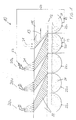
- Figure 1 shows schematically the operation in a prior art. Shown is a section along a device with a diffuser 10, in which there is material 11, which is moved on a sieve plate 12, in the direction of arrow 13.
- the material 11 is fibrous, for example processed sugar cane or sugar cane bagasse, and is in 1 coming from the left into the diffuser 10 in a manner not shown.
- the sieve plate 12 stands stationary, also not shown driving devices ensure the transport in the direction of arrow 13.
- the material 11 should be continuously leached out and substances contained in it, in particular sugar, of course, should be obtained. This is done by applying imbibition liquid 21 to the good 11 from above via liquid feed devices 20.
- the imbibition liquid 21 is initially, for example, hot water and is added to the section of the material 11 that is most conveyed in the direction of the arrow 13 in the diffuser 10.
- This imbibition liquid 21 then runs through the material 11 into the liquid collecting vessel 22e, which is also on the far right. At this point she had already leached some sugar out of Gut 11.
- the sugar content is still very low here, especially since the leaching has taken place from a good component 11 which has already largely been deprived of its sugar content beforehand.
- the liquid content is supplied to the liquid feed device 20e, which is closest in the direction of the arrow 13, via a conveying device 23, which is only indicated schematically.
- the now slightly sugar-containing imbibition liquid 21 is again given from above onto the top of the good 11 in the diffuser 10, flows through this good layer again with simultaneous leaching out of the now somewhat more sugar-containing good 11 and reaches the second juice pan 22d. This process is repeated again and again upstream.
- the letter 20 attached to the reference symbol 20 illustrates from which liquid collection vessel their imbibition liquid is supplied.
- the liquid application devices 20 dispense the imbibition liquid 21 more or less vertically in a curtain-like shape onto the surface of the region of the material below them, so that it is practically linear or stripe-shaped, namely in a line or a stripe across the diffuser 10, the material 11 passing underneath is correspondingly wetted from above. Due to the continuous transport in the direction of arrow 13 Each surface area of the goods is thus provided with liquid from above at several points in time, which then flows downwards.
- a liquid application device 20 is to be provided for each liquid collection vessel 22, and care must be taken to ensure that the imbibition liquid 21 emanating from a particular liquid application device 20 never gets into a liquid collection vessel 22 that is not assigned to it, since this leads to the effectiveness of the entire process disturbing falsification and impairment of the countercurrent principle.
- the next lower letter is therefore to be regarded as the assigned liquid collecting vessel; the liquid collecting device 22b is associated with the liquid collecting device 20c and so on.
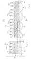
- FIG. 2 shows the avoidance of this unfavorable, recognized effect according to the invention.
- FIG. 2 Basically, the mode of operation and also the representation of the system in FIG. 2 is similar to that in FIG. 1: Again, material 11 is transported in a diffuser 10 on a sieve plate 12 in the direction of arrow 13. Liquid feed devices 20 supply the surface of the material 11 in the diffuser 10 with imbibition liquid 21, which flows through the material 11 to the sieve plate 12 and through it into liquid collecting vessels 22.
- conveying devices 23 are provided, which feed the contents of a liquid collecting vessel 22 to the liquid feeding device 20 located upstream of the respective flow.
- Liquid irrigation devices 20 have now become veritable sprinkling devices.
- the cross section of FIG. 2 taken at a certain point in time also shows the angle at which a liquid drop runs through , each practically constant.
- the imbibition liquid portions striking the surface of the material 11 in a certain surface area 30 also in a percolation area that is practically the same size and assigned 31 with the leached components of the material 11 arrive on the sieve tray 12, flow through it and thus flow into the assigned liquid collection container 22.
- edge areas between each two adjacent surface areas 30 on the surface of the material 11 can be kept free from irrigation.
- these edge areas are less than half of the entire surface, preferably less than a third and particularly preferably also less than a tenth of the surface. The slightly reduced utilization of the capacity of the diffuser is accepted in favor of avoiding bypass formation and recirculation.
- FIG. 3 also shows a section perpendicular to FIG. 2, from which it can be seen in particular that the conveyance of the imbibition liquid from the liquid collection container 22 to the nearest liquid feed device 20 can be carried out upstream of the good next to the conveyance of the material 11 in the diffuser 10.
- Suitable juice distribution devices can ensure that the irrigation is as uniform as possible.
- FIGS. 2 and 3 jointly indicate that here, for example, the liquid feed device 20d consists of a field of 3 ⁇ 4, that is to say a total of 12, discharge points which discharge the imbibition liquid from the adjacent liquid collection container 22d, for which purpose they are suitably connected to one another.
Landscapes
- Chemical & Material Sciences (AREA)
- Chemical Kinetics & Catalysis (AREA)
- Life Sciences & Earth Sciences (AREA)
- Biochemistry (AREA)
- Organic Chemistry (AREA)
- Extraction Or Liquid Replacement (AREA)
Priority Applications (6)
| Application Number | Priority Date | Filing Date | Title |
|---|---|---|---|
| EP96110540A EP0790318A1 (fr) | 1996-06-28 | 1996-06-28 | Procédé d'épuisement en continu de matière fibreuse, en particulier de canne à sucre et/ou de bagasse |
| EG57697A EG21352A (en) | 1996-06-28 | 1997-06-21 | Installation for continuous leaching of fibrous material in particular for sugar cane and/or bagasse |
| IDP972228A ID17462A (id) | 1996-06-28 | 1997-06-26 | Instalasi untuk pelepasan materi fibrosa, terutama dalam gula tebu dan atau ampas tebu |
| AU28366/97A AU721580B2 (en) | 1996-06-28 | 1997-06-27 | Installation for continuous leaching of fibrous material, in particular of sugar cane and/or bagasse |
| ZA9705725A ZA975725B (en) | 1996-06-28 | 1997-06-27 | Installation for continuous leaching of fibrous material, in particular of sugar cane and/or bagasse. |
| BR9703798A BR9703798A (pt) | 1996-06-28 | 1997-06-30 | Instalação para lixiviação contínua de material fibroso em particular cana-de-açucar e/ou bagaço |
Applications Claiming Priority (1)
| Application Number | Priority Date | Filing Date | Title |
|---|---|---|---|
| EP96110540A EP0790318A1 (fr) | 1996-06-28 | 1996-06-28 | Procédé d'épuisement en continu de matière fibreuse, en particulier de canne à sucre et/ou de bagasse |
Publications (1)
| Publication Number | Publication Date |
|---|---|
| EP0790318A1 true EP0790318A1 (fr) | 1997-08-20 |
Family
ID=8222955
Family Applications (1)
| Application Number | Title | Priority Date | Filing Date |
|---|---|---|---|
| EP96110540A Withdrawn EP0790318A1 (fr) | 1996-06-28 | 1996-06-28 | Procédé d'épuisement en continu de matière fibreuse, en particulier de canne à sucre et/ou de bagasse |
Country Status (6)
| Country | Link |
|---|---|
| EP (1) | EP0790318A1 (fr) |
| AU (1) | AU721580B2 (fr) |
| BR (1) | BR9703798A (fr) |
| EG (1) | EG21352A (fr) |
| ID (1) | ID17462A (fr) |
| ZA (1) | ZA975725B (fr) |
Cited By (1)
| Publication number | Priority date | Publication date | Assignee | Title |
|---|---|---|---|---|
| DE102011113792A1 (de) | 2011-09-20 | 2013-03-21 | Holger Kleim | Verfahren und Vorrichtung zur Behandlung von Feststoffen mit feiner Körnung sowie Flüssigkeiten in Behältern |
Families Citing this family (1)
| Publication number | Priority date | Publication date | Assignee | Title |
|---|---|---|---|---|
| BRPI0900946A8 (pt) * | 2009-04-17 | 2017-05-16 | Empral Desenvolvimento De Equipamentos Ltda | Difusor horizontal com sistema de deslocamento da cana-de-açúcar e outros produtos por meio de cabos e empurradores retráteis |
Citations (5)
| Publication number | Priority date | Publication date | Assignee | Title |
|---|---|---|---|---|
| BE681580A (fr) * | 1965-06-04 | 1966-10-31 | ||
| DE1567272A1 (de) * | 1961-09-30 | 1970-11-05 | Sucreries Et De Distillerie D | Kontinuierliches Verfahren zum Extrahieren von Zucker aus Zuckerrohr oder Bagasse |
| DE1949286A1 (de) * | 1968-09-26 | 1971-02-25 | Fairymead Sugar Company Ltd | Zuckerrohrextraktor |
| FR2504151A1 (fr) * | 1981-04-17 | 1982-10-22 | Thirel Jean Pierre | Installation pour l'extraction du jus sucre de la bagasse de canne a sucre ou produit analogue |
| EP0255555A1 (fr) * | 1986-08-02 | 1988-02-10 | Braunschweigische Maschinenbauanstalt AG | Appareil de lessivage en continu d'une matière fibreuse, feutrée, en particulier de canne à sucre broyée |
-
1996
- 1996-06-28 EP EP96110540A patent/EP0790318A1/fr not_active Withdrawn
-
1997
- 1997-06-21 EG EG57697A patent/EG21352A/xx active
- 1997-06-26 ID IDP972228A patent/ID17462A/id unknown
- 1997-06-27 ZA ZA9705725A patent/ZA975725B/xx unknown
- 1997-06-27 AU AU28366/97A patent/AU721580B2/en not_active Ceased
- 1997-06-30 BR BR9703798A patent/BR9703798A/pt active Search and Examination
Patent Citations (6)
| Publication number | Priority date | Publication date | Assignee | Title |
|---|---|---|---|---|
| DE1567272A1 (de) * | 1961-09-30 | 1970-11-05 | Sucreries Et De Distillerie D | Kontinuierliches Verfahren zum Extrahieren von Zucker aus Zuckerrohr oder Bagasse |
| BE681580A (fr) * | 1965-06-04 | 1966-10-31 | ||
| DE1567245A1 (de) * | 1965-06-04 | 1970-06-25 | Braunschweigische Maschb Ansta | Vorrichtung und Verfahren zur kontinuierlichen Extraktion des Zuckers aus Bagasse |
| DE1949286A1 (de) * | 1968-09-26 | 1971-02-25 | Fairymead Sugar Company Ltd | Zuckerrohrextraktor |
| FR2504151A1 (fr) * | 1981-04-17 | 1982-10-22 | Thirel Jean Pierre | Installation pour l'extraction du jus sucre de la bagasse de canne a sucre ou produit analogue |
| EP0255555A1 (fr) * | 1986-08-02 | 1988-02-10 | Braunschweigische Maschinenbauanstalt AG | Appareil de lessivage en continu d'une matière fibreuse, feutrée, en particulier de canne à sucre broyée |
Cited By (1)
| Publication number | Priority date | Publication date | Assignee | Title |
|---|---|---|---|---|
| DE102011113792A1 (de) | 2011-09-20 | 2013-03-21 | Holger Kleim | Verfahren und Vorrichtung zur Behandlung von Feststoffen mit feiner Körnung sowie Flüssigkeiten in Behältern |
Also Published As
| Publication number | Publication date |
|---|---|
| ZA975725B (en) | 1998-01-30 |
| BR9703798A (pt) | 1998-11-10 |
| ID17462A (id) | 1998-01-08 |
| EG21352A (en) | 2001-09-30 |
| AU2836697A (en) | 1998-01-15 |
| AU721580B2 (en) | 2000-07-06 |
Similar Documents
| Publication | Publication Date | Title |
|---|---|---|
| DE2848459C2 (de) | Vorrichtung zur Herstellung einer Faserbahn | |
| DE69603173T2 (de) | Ablagerungsvorrichtung für eine flüssigkeit, gas und partikelförmiges material enthaltendes fluidum, sowie eine mit einer solchen vorrichtung ausgerüsteten reinigungsanlage und reinigungsverfahren | |
| CH622304A5 (fr) | ||
| DE69916999T2 (de) | Verfahren und Vorrichtung zur Hochgeschwindigkeitsbehandlung eines Bandes | |
| DE1510368A1 (de) | Vorrichtung zum Abscheiden von aufgeloesten Faserflocken aus einem Transportluftstrom | |
| DD201848A5 (de) | Fertigungsmaschine fuer zigaretten | |
| DE102006018101A1 (de) | Aufbereitungseinheit zur Aufbereitung mindestens eines Filtertowstreifens sowie eine Vorrichtung mit mindestens zwei derartigen Aufbereitungseinheiten | |
| DE2129849A1 (de) | Verfahren und Vorrichtung zum Extrahieren von Bestandteilen aus festen Stoffen | |
| DE2559992C3 (de) | Tropfenabscheider bei einer Vorrichtung zum Kühlen durch Verdunsten eingespritzter Flüssigkeit | |
| DE2532528B2 (de) | Verfahren zur Herstellung eines bestimmten Verteilungsgesetzes des Durchflusses in einem Mediumsstrom, Vorrichtung zur Durchführung des Verfahrens bzw. der Vorrichtung | |
| DE2928234A1 (de) | Kanalluftfilter | |
| DE2137139A1 (de) | Verfahren und Vorrichtung zum Reim gen der aus einem Füllschacht fur Faser flocken austretenden Abluft | |
| DE69020165T2 (de) | Egalisieranordnung für lötstoff. | |
| DE2621513C2 (de) | Vorrichtung zum Herstellen eines in einer Presse zu Spanplatten o.dgl. zu verdichtenden Vlieses | |
| DE3126853C2 (fr) | ||
| DE649036C (de) | Verfahren und Vorrichtung zum kontinuierlichen Destillieren von Trestern | |
| DE1584862B1 (de) | Klaervorrichtung fuer Abwasser mit langsam sinkenden Feststoffteilchen | |
| AU721580B2 (en) | Installation for continuous leaching of fibrous material, in particular of sugar cane and/or bagasse | |
| DE1567272C3 (de) | Verwendung einer Gegenstromextrak tionsvorrichtung zur Gewinnung von Zuckersaft aus Zuckerrohr | |
| DE1567247B2 (de) | Vorrichtung zum kontinuierlichen auslaugen von zerkleinertem zuckerrohr | |
| DE1053470B (de) | Verfahren zur Extraktion in horizontalen Becherwerksextrakteuren | |
| DE1460230C (de) | Verfahren und Vorrichtung zur Behandlung von losem Fasergut | |
| DE1567247C3 (de) | Vorrichtung zum kontinuierlichen Auslaugen von zerkleinertem Zuckerrohr | |
| DE2425512C3 (de) | Bausatz für Vorrichtungen zum Auslaugen von Zuckerrohr Braunschweigische Maschin enbauanstalt, 3300 Braunschweig | |
| DE3026629C2 (de) | Reinigungsgerät für Grüne-Erbsen |
Legal Events
| Date | Code | Title | Description |
|---|---|---|---|
| PUAI | Public reference made under article 153(3) epc to a published international application that has entered the european phase |
Free format text: ORIGINAL CODE: 0009012 |
|
| 17P | Request for examination filed |
Effective date: 19970108 |
|
| AK | Designated contracting states |
Kind code of ref document: A1 Designated state(s): BE DE FR GB |
|
| 17Q | First examination report despatched |
Effective date: 19991116 |
|
| GRAG | Despatch of communication of intention to grant |
Free format text: ORIGINAL CODE: EPIDOS AGRA |
|
| STAA | Information on the status of an ep patent application or granted ep patent |
Free format text: STATUS: THE APPLICATION IS DEEMED TO BE WITHDRAWN |
|
| 18D | Application deemed to be withdrawn |
Effective date: 20010103 |