EP0790363B1 - Fassadensystem für vertikale, diagonale und horizontale Verkleidungen - Google Patents
Fassadensystem für vertikale, diagonale und horizontale Verkleidungen Download PDFInfo
- Publication number
- EP0790363B1 EP0790363B1 EP97250026A EP97250026A EP0790363B1 EP 0790363 B1 EP0790363 B1 EP 0790363B1 EP 97250026 A EP97250026 A EP 97250026A EP 97250026 A EP97250026 A EP 97250026A EP 0790363 B1 EP0790363 B1 EP 0790363B1
- Authority
- EP
- European Patent Office
- Prior art keywords
- cross
- bar
- glass support
- facade system
- functional glass
- Prior art date
- Legal status (The legal status is an assumption and is not a legal conclusion. Google has not performed a legal analysis and makes no representation as to the accuracy of the status listed.)
- Expired - Lifetime
Links
- 239000011521 glass Substances 0.000 claims description 47
- 239000002184 metal Substances 0.000 claims description 10
- 238000005553 drilling Methods 0.000 claims description 5
- 238000007789 sealing Methods 0.000 claims description 2
- 238000006073 displacement reaction Methods 0.000 claims 1
- 230000037431 insertion Effects 0.000 claims 1
- 238000003780 insertion Methods 0.000 claims 1
- 229910001220 stainless steel Inorganic materials 0.000 claims 1
- 239000010935 stainless steel Substances 0.000 claims 1
- 238000010276 construction Methods 0.000 description 4
- 238000009434 installation Methods 0.000 description 3
- 238000010079 rubber tapping Methods 0.000 description 3
- 238000005253 cladding Methods 0.000 description 2
- 239000000284 extract Substances 0.000 description 2
- 239000005340 laminated glass Substances 0.000 description 2
- 239000000463 material Substances 0.000 description 2
- 238000003860 storage Methods 0.000 description 2
- 230000006978 adaptation Effects 0.000 description 1
- 239000002131 composite material Substances 0.000 description 1
- 238000011161 development Methods 0.000 description 1
- 230000018109 developmental process Effects 0.000 description 1
- 238000009422 external insulation Methods 0.000 description 1
- 238000009413 insulation Methods 0.000 description 1
- 230000003993 interaction Effects 0.000 description 1
- 238000004519 manufacturing process Methods 0.000 description 1
- 238000000034 method Methods 0.000 description 1
- 238000002360 preparation method Methods 0.000 description 1
- 125000006850 spacer group Chemical group 0.000 description 1
- XLYOFNOQVPJJNP-UHFFFAOYSA-N water Substances O XLYOFNOQVPJJNP-UHFFFAOYSA-N 0.000 description 1
Images



Classifications
-
- E—FIXED CONSTRUCTIONS
- E04—BUILDING
- E04B—GENERAL BUILDING CONSTRUCTIONS; WALLS, e.g. PARTITIONS; ROOFS; FLOORS; CEILINGS; INSULATION OR OTHER PROTECTION OF BUILDINGS
- E04B2/00—Walls, e.g. partitions, for buildings; Wall construction with regard to insulation; Connections specially adapted to walls
- E04B2/88—Curtain walls
- E04B2/96—Curtain walls comprising panels attached to the structure through mullions or transoms
- E04B2/965—Connections of mullions and transoms
Definitions
- the invention relates to a facade system for vertical, diagonal and horizontal Cladding of buildings according to the generic concept of the main claim.
- a facade system for vertical, diagonal and horizontal Cladding of buildings according to the generic concept of the main claim.
- Such a system is known from DE-C-3 742 747.
- facade system consists of metal hollow profiles made of posts and lockable bars.
- Those not shown in the extract from the prospectus Filling elements, in particular laminated glass elements are in the by post and latch formed metal frame arranged.
- the loads of the filling elements are taken up by a carrier element, which in the company brochure with a bolt holder is referred to as the connection between the bolt and Post is manufactured.
- holes are made in the respective end area Carrier element is provided, through which a threaded screw can be inserted, with a countersunk rivet nut arranged in the bolt can be connected.
- the Carrier element in the middle has an upwardly extending web, which with a corresponding hole is provided.
- the middle itself is also a hole is provided. Since the attachment of the support element to the post and on the bolts with cap screws must cover the heads so-called glass holder can be inserted into the carrier element.
- the adaptation the support element to different glass thicknesses is done in such a way that Carrier element is cut to the appropriate width from the extruded profile.
- the known system has retaining strips, which in the Threaded bolts and posts arranged with matching bolts and matching nuts are attachable.
- Threaded sleeves made of plastic can be arranged by can be screwed in on both sides.
- threaded bolts are first in the threaded holes provided for the posts and transoms screwed in, then the threaded sleeve onto the protruding threaded bolts screwed. Then thread bolts from the other side into the Threaded sleeve screwed, which is through corresponding holes in the Extend the holding strips.
- these are protruding Threaded stud head screws are screwed on to secure the retaining strips.
- the Fastening of the horizontally running holding elements at the crossing point between Posts and transoms are made using M6 threaded bolts screwed into the support element.
- the posts, the transom and the are in the grooves Holding strips arranged according to molded seals.
- the precise arrangement of the threaded holes is also complex in mullions and transoms for receiving the threaded bolts carrying the retaining strips.
- the assembly through the constant adjustment of the protruding Length of the threaded bolt increases, otherwise the distance in relation to the thickness the filling elements is too small or too large and in the latter case the depth of the Head screw is no longer sufficient for a secure attachment of the retaining strips.
- the Type of adjustment of the width of the support element to different glass thicknesses is problematic, as this can lead to confusion and the effort for the Storage of the spare parts increased accordingly.
- DE 3843737 A1 discloses a mullion-transom system in which one appropriately trained transom holders, the transoms can be releasably connected to the post.
- An essential characteristic of the known bar holder is that it can be inserted into the bar and in this longitudinally displaceable fitting, on which two plug pins for Introduction to corresponding holes are arranged on the post.
- the fitting piece is connected to an elongated guide rail that with an outwardly extending nose-shaped profile of the bolt interacts.
- the guide rail points at to fasten the bolt holder to the bolt End a threaded hole into which one can be inserted through a hole in the bolt Screw can be screwed in.
- the three-point bearing is the one facing the post Front side of the guide rail on the long side of the outwardly extending nose-shaped profile of the post to the system.
- a threaded screw extending through the guide rail with its cone-shaped approach, so that there is a kind of bracketing.
- DE 3742747 C2 shows a generic facade system in which a detachable one Connection of the bolt to the post is carried out by means of a connecting piece which can be inserted at the end into the bar designed as a hollow profile.
- the tour takes place here solely through the cross-sectional contour of the connector.
- the connector points a laterally open push channel that runs along the oblique direction of the bolt the inclined surface of which is supported by a fastening means designed as a fixing pin is inserted from the outside through a hole in the front of the transom.
- the external part of the fixing pin can be an external insulation profile after installation fix, which to avoid cold bridges usually at this point is provided.
- As a fastening element for the retaining strip there is a kind of clip connection here intended.
- the object of the invention is the generic facade system for vertical, diagonal and to improve horizontal cladding of buildings so that when in use as few parts as possible both for the preparatory workshop and on the construction site Erection of the facade is easy to assemble and the overall system is stable and is torsionally rigid.
- a bar holder known per se is used for releasable attachment of mullions and transoms.
- This bar holder is in the Workshop fixable in the bolt, so that when handling the bolt on the construction site Bar holder cannot fall out.
- the mounting screw can also be used to move the bolt holder the pins of the socket pins in the holes arranged in the post introduce. It is not possible to hold the latch until it is finally attached required because after inserting the pin the bolt is in its final position has taken.
- Another advantage over the known facade system arises from the fact that the multifunctional glass carrier does not directly with the Bolt, but is connected to the bolt holder inserted into the bolt, in addition to the known direct attachment to the post.
- the support width of the multifunctional glass support is changeable, whereby in Difference from the known prior art in adapting the basic element the most frequently used glass thickness always has the same width.
- Another aspect in terms of easy installation of the facade system according to the invention is the attachment of the known Retaining strips on the metal frame. Instead of the expensive to assemble threaded bolts and the associated threaded holes to be fitted precisely Self-drilling screws are used with a pressure spacer sleeve interacting guide sleeve are guided. This procedure has the great advantage that the previous installation of There are no threaded holes or rivet nuts in the mullion and in the transoms can. Another advantage is that to attach the glass support Tapping holes can be omitted, since by using so-called self-tapping and self-locking tribolar screws simple Holes are sufficient. It has also been ensured that the heads of all Fastening screws have the same type and the same dimensions, so that only one screwing tool is required for assembly.
- the multifunctional glass support according to the invention is characterized in that it is universally applicable, once with regard to different thicknesses of the Filling material and on the other hand with regard to the transfer of different sizes Loads.
- the multifunctional glass support serves to hold the fixing screw connection or end screw connection of the retaining strips.
- the multifunctional glass support has transverse grooves into which one aspect Edition widening profile can be inserted, so that the edition of the thickness of the Filling material is adjusted.
- Another hole is for the second aspect provided that an arm of the multifunctional glass carrier not only with one, but to be able to fasten with two threaded screws in the transom holder.
- the multifunctional glass support according to the invention in Difference from the known prior art in the middle one down and one down extending web on top, so that through the double web thereby formed two threaded screws can be inserted. This is especially true for the Corner connection of importance, since then usually an arm of the multifunctional Glass carrier is separated. All heads of the fastening screws are in the Retractable support element so that a glass holder covering the cap screws can be omitted.
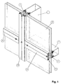
- Figure 1 is a perspective view of the crossing point Facade system according to the invention shown after final assembly.
- the essential elements of this facade system are that of a hollow profile manufactured post 1 and the connectable also from a hollow profile manufactured bar 2.
- Metal frames are the filling elements, here one out of two in this exemplary embodiment Existing laminated glass pane element 12 arranged.
- the end towards the outside form retaining strips 14, 20, which, with corresponding fastenings will be explained in detail below with the metal frame are connected.
- the latch 2 and the holding strips 14, 20 are correspondingly molded seals 5, 6, 13 arranged.
- FIG 2 shows like Figure 1 the same section of the facade system, this time but in an exploded view.
- the Crossing area of the holding strips 14, 20 is in this embodiment a total of three screws 16 fastened with one not recognizable here Sealing washer are provided.
- the to the vertical continuous holding bar 20th abutting horizontal holding strips 14 are in the stop area with a End seal 15 provided.
- the three aforementioned fastening screws 16 are screwed into the multifunctional glass support 8. For that are in multifunctional glass support 8 transversely extending threaded holes 21 arranged (see Fig. 5).
- the holding strips 14, 20 lie outside the intersection area.
- reference number 17 is a self-drilling screw, which is marked with a Pressure distance sleeve 19 cooperating guide sleeve 18 is guided.
- the guide sleeve 18 through the respective bore of the retaining strips 14,20 inserted through and the pressure distance sleeve 19 slightly from the back postponed.
- the self-drilling screw 17 by hand in the guide sleeve 18 inserted as far as possible.
- the screw 17 is rotated, which is with its specially trained Then drill tip into the nose-shaped profile of the post 1 or Bolt 2 screwed in.
- the fastening screws 17 and thus the retaining strips 14.20 attached.
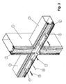
- FIG 3 shows comparable to Fig. 1 in a perspective view of the type of Attachment of the multifunctional glass support 8.
- the multifunctional glass support 8 is designed so that the attachment is reinforced at extremely large loads can be.
- a further transverse bore 22 in the respective support arm of the multifunctional Glass carrier 8 arranged a further transverse bore 22 (see Figure 5) in the Additional screws 10a can be screwed in.
- the facade Attachment is via the double web 23 and a support arm of the multifunctional glass support 8.
- This type of attachment results in a very stable and torsion-resistant construction.
- FIG. 4 shows, like Fig. 3, the same section of the facade wall construction, however in an exploded view.
- This latch holder 3 has a guide rail 24 and two socket pins 25, the pins of which can be inserted into corresponding bores 26 of the post.
- the Guide rail 24 acts with the outwardly extending nose-shaped Profiling of the bar 2 together.
- the end region of the bar 2 has an elongated hole 27 through which one Mounting screw 4 is pluggable.
- the latch holder 3 is so far in the bolt 2 pushed in and fixed by the mounting screw that the bolt 2 can be pushed between two set posts 1.
- the transom holder 3 By moving the Assembly screw 4, the transom holder 3 can be moved in the direction of the post 1 until the pins of the socket pins 25 into the bore 26 of the post 1 intervention.
- the actual attachment now takes place in such a way that the Fixing screws 10 through the multifunctional glass support 8 and through the Bores 28 of the bolt 2 are inserted in order then in the guide rail 24 attached threaded holes 29 to be screwed. That way the latch 2, the latch holder 3 and the multifunctional glass support 8 are attached.
- a bore can be provided instead of the threaded bore 29 a so-called self-tapping and self-locking tribolar screw is screwed in.
- FIG. 5 shows the multifunctional glass carrier 8 in a perspective view essential elements of this multifunctional glass support 8 and their Interaction with the other parts of the facade system are already in the previous figures have been explained in detail. More clearly than in the In this illustration, previous figures show the possibility of widening detect.
- 8 are transverse in the arms of the multifunctional glass support Grooves 30 attached, so that a circulation widening profile 9 inserted therein can be.
- the representation is still one over the length of the the respective support arm extending groove 32.
- This groove is too on the back of the multifunctional glass support 8, which is not visible here arranged.
- This groove 32 is used to for special cases in which the glass composite on top of the underlying panes before contact with them standing water should be protected, attach a cover z. B. clip in to be able to.
Landscapes
- Engineering & Computer Science (AREA)
- Architecture (AREA)
- Physics & Mathematics (AREA)
- Electromagnetism (AREA)
- Civil Engineering (AREA)
- Structural Engineering (AREA)
- Load-Bearing And Curtain Walls (AREA)
Description
- Figur 1
- in einer perspektivischen Ansicht den Kreuzungspunkt eines erfindungsgemäßen Fassadensystems nach der Endmontage
- Figur 2
- wie Fig. 1 als Explosionsdarstellung
- Figur 3
- in einer perspektivischen Ansicht die Befestigung des erfindungsgemäßen multifunktionalen Trägerelementes im Kreuzungspunkt
- Figur 4
- wie Fig. 3 in einer Explosionsdarstellung
- Figur 5
- in einer perspektivischen Ansicht das multifunktionale Trägerelement.
Claims (12)
- Fassadensysteme für vertikale, diagonale und horizontale Verkleidungen von Bauten, bestehend aus metallischen Hohlprofilen hergestellten Pfosten (1) und damit über einen Riegelhalter lösbar verbundenen Riegeln (2), aus Füllelementen, insbesondere Verbundglasscheibenelemente (12), die in den Pfosten (1) und Riegel (2) gebildeten Metallrahmen angeordnet sind und deren Lasten durch im Pfosten (1) und Riegel (2) befestigbare Trägerelemente aufgenommen werden sowie lösbar mit dem Metallrahmen verbindbare Halteleisten (14, 20) und in Längsnuten des Metallrahmens und der Halteleisten (14, 20) angeordneter Dichtelemente (5, 6, 13), wobei
der in den Riegel (2) einschiebbare, eine Führungsschiene (24) und mindestens einen Steckbolzen (25) aufweisende Riegelhalter (3) vor der Befestigung des Riegels (2) mit dem Pfosten (1) im Riegel (2) fixiert ist dadurch gekennzeichnet, dass das Trägerelement als multifunktionaler Glasträger (8) ausgebildet und mit einer veränderbaren Auflagenbreite versehen ist und das Befestigungselement für die Halteleiste (14, 20) eine mit einer Andruckdistanzhülse (19) zusammenwirkende Führungshülse (18) für eine selbstbohrende Schraube (17) aufweist. - Fassadensystem nach Anspruch 1,
dadurch gekennzeichnet, dass für die Fixierung und Verschiebung des Riegelhalters (3) der Riegel (2) in einer nach außen sich erstreckenden nasenförmigen Profilierung ein Langloch (27) aufweist, durch das eine in eine Gewindebohrung der Führungsschiene (24) einschraubbare Montageschraube (4) steckbar ist. - Fassadensystem nach Anspruch 2,
dadurch gekennzeichnet, dass die Länge des Langloches (4) größer ist als die Einstecktiefe des Riegelhalters (3) im Pfosten (1). - Fassadensystem nach Anspruch 1,
dadurch gekennzeichnet, daß zur Befestigung des multifunktionalen Glasträgers (8) die Führungsschiene (24) des Riegelhalters (3) mindestens eine weitere Bohrung oder Gewindebohrung (29) aufweist. - Fassadensystem nach Anspruch 1,
dadurch gekennzeichnet, daß im Kreuzungspunkt Pfosten(1 )/Riegel (2) zur Vorfixierung der Halteleisten (14,20) mindestens je Halteleiste (14,20) eine in den multifunktionalen Glasträger (8) einschraubbare Befestigungsschraube (16) vorgesehen ist und der multifunktionale Glasträger (8) dafür mindestens eine Bohrung oder Gewindebohrung (21) aufweist. - Fassadensystem nach Anspruch 1,
dadurch gekennzeichnet, daß der multifunktionale Glasträger (8) querliegende Nuten (30) zur Aufnahme mindestens eines Auflagenverbreiterungsprofiles (9) aufweist. - Fassadensystem nach Anspruch 1,
dadurch gekennzeichnet, daß der multifunktionale Glasträger (8) mindestens eine weitere querliegende Bohrung (22) zur Aufnahme einer Zusatzschraube (10a) aufweist. - Fassadensystem nach Anspruch 1,
dadurch gekennzeichnet, daß der multifunktionale Glasträger (8) in der Mitte einen nach unten und nach oben sich erstreckenden Steg (23) aufweist, der mit mindestens einer querliegenden Bohrung zur Befestigung am Pfosten (1) versehen ist. - Fassadensystem nach Anspruch 1,
dadurch gekennzeichnet, daß die Köpfe der Befestigungselemente (10,10a,11)zur Verbindung des multifunktionalen Glasträgers (8) mit Pfosten (1) und Riegel (2) im multifunktionalen Glasträger (8) versenkbar sind. - Fassadensystem nach Anspruch 1,
dadurch gekennzeichnet, daß der multifunktionale Glasträger (8) durchgehend auf der Vor- und Rückseite des jeweiligen Auflagearmes eine über die Länge des Auflagearmes sich erstreckende Nut (32) aufweist. - Fassadensystem nach einem der Ansprüche 1 bis 10,
dadurch gekennzeichnet, daß in der Montageebene des multifunktionalen Glasträgers (8) und der Halteleisten (14,20) die aus einem rostfreien Edelstahl hergestellten Befestigungsschrauben (10,10a,11,17) mit Schraubenköpfen gleichen Typs und gleicher Größe versehen sind. - Fassadensystem nach Anspruch 11,
dadurch gekennzeichnet, daß in der Montageebene des multifunktionalen Glasträgers (8) die Befestigungsschrauben (10,10a,11) als selbstfurchende und selbsthemmende Tribolarschrauben ausgebildet sind.
Applications Claiming Priority (2)
| Application Number | Priority Date | Filing Date | Title |
|---|---|---|---|
| DE19606906 | 1996-02-13 | ||
| DE19606906A DE19606906C2 (de) | 1996-02-13 | 1996-02-13 | Fassadensystem für vertikale, diagonale und horizontale Verkleidungen von Bauten |
Publications (3)
| Publication Number | Publication Date |
|---|---|
| EP0790363A2 EP0790363A2 (de) | 1997-08-20 |
| EP0790363A3 EP0790363A3 (de) | 1998-10-07 |
| EP0790363B1 true EP0790363B1 (de) | 2003-05-28 |
Family
ID=7786290
Family Applications (1)
| Application Number | Title | Priority Date | Filing Date |
|---|---|---|---|
| EP97250026A Expired - Lifetime EP0790363B1 (de) | 1996-02-13 | 1997-02-07 | Fassadensystem für vertikale, diagonale und horizontale Verkleidungen |
Country Status (2)
| Country | Link |
|---|---|
| EP (1) | EP0790363B1 (de) |
| DE (2) | DE19606906C2 (de) |
Families Citing this family (16)
| Publication number | Priority date | Publication date | Assignee | Title |
|---|---|---|---|---|
| DE19822103A1 (de) * | 1998-05-11 | 1999-12-02 | Mannesmann Ag | Fassadensystem für die Verkleidung eines Bauwerkes |
| DE19854203C2 (de) * | 1998-11-24 | 2002-04-25 | Lanco Lange Fenster Fassaden | Pfosten/Riegel-Fassade für ein Gebäude |
| DE19953557C1 (de) * | 1999-11-03 | 2001-07-12 | Rp Technik Gmbh | Verkleidungssystem für Fassaden und Dächer von Bauwerken |
| DE10011028A1 (de) * | 2000-03-07 | 2001-09-27 | Sfs Ind Holding Ag Heerbrugg | Profile zum Einsatz für die Halterung von Verglasungs- oder sonstigen Fassadenelementen |
| DE202006008511U1 (de) * | 2006-05-30 | 2006-07-27 | Rehau Ag + Co | Konstruktionsanordnung |
| EP2320000A1 (de) * | 2009-11-04 | 2011-05-11 | Unilux AG | Pfosten-Riegel-Konstruktion und Glasträger für eine Pfosten-Riegel-Konstruktion |
| US9045900B2 (en) * | 2012-10-02 | 2015-06-02 | Technical Glass Products | Barrier to heat transparent wall system |
| BE1021515B1 (nl) * | 2012-12-12 | 2015-12-04 | Reynaers Aluminium, Naamloze Vennootschap | Steun en constructie voor gevelpanelen in een vliesgevel en vliesgevel |
| DE202013105585U1 (de) * | 2013-12-09 | 2015-03-10 | SCHÜCO International KG | Pfosten-Riegel-Konstruktion |
| DE102014005110B4 (de) * | 2014-04-05 | 2021-09-30 | Petschenig Glastec Gmbh | Halterung |
| WO2017083990A1 (de) | 2015-11-18 | 2017-05-26 | Jansen Ag | Dichtungsprofil |
| CN105780988A (zh) * | 2016-04-27 | 2016-07-20 | 现代幕墙系统技术(苏州)有限公司 | 节能混合幕墙系统 |
| EP3529431B1 (de) | 2017-01-09 | 2021-11-03 | Jansen AG | Tragstruktur für fassadenelemente |
| WO2019045349A1 (ko) * | 2017-08-28 | 2019-03-07 | 구하경 | 철제 가구용 프레임 및 프레임 조립체 |
| DE202018106077U1 (de) * | 2018-10-24 | 2018-11-07 | SCHÜCO International KG | Glasträgerkonstruktion und Rahmenkonstruktion |
| WO2020118390A1 (pt) * | 2018-12-12 | 2020-06-18 | Leodir Francisco Do Prado | Disposição construtiva aplicada a fachada com perfis funcionais componíveis |
Family Cites Families (7)
| Publication number | Priority date | Publication date | Assignee | Title |
|---|---|---|---|---|
| US4428171A (en) * | 1982-03-12 | 1984-01-31 | Atlantic Richfield Company | Thermal storefront system |
| GB2176217B (en) * | 1985-03-30 | 1988-10-05 | James Alan Macey | Curtain walls |
| DE3742747C1 (en) * | 1987-12-17 | 1989-05-03 | Wicona Bausysteme | Butt connection of a transom profile to a frame or post profile for windows, doors, facades or the like |
| DE3823939A1 (de) * | 1988-04-11 | 1989-10-19 | Gartner & Co J | Vorrichtung zur befestigung von verglasungen |
| DE3843737A1 (de) * | 1988-12-22 | 1990-07-05 | Mannesmann Ag | Riegelhalter fuer eine fassadenwandkonstruktion |
| DE4000770A1 (de) * | 1990-01-12 | 1991-07-18 | Reynolds Aluminium Deutschland | Verbindung des stosses zwischen riegel und pfosten an einem traggerippe fuer eine oder an einer fassadenwand |
| DE4040006A1 (de) * | 1990-12-14 | 1992-06-17 | Glasbau Seele Gmbh | Glaswand |
-
1996
- 1996-02-13 DE DE19606906A patent/DE19606906C2/de not_active Expired - Fee Related
-
1997
- 1997-02-07 EP EP97250026A patent/EP0790363B1/de not_active Expired - Lifetime
- 1997-02-07 DE DE59710148T patent/DE59710148D1/de not_active Expired - Fee Related
Also Published As
| Publication number | Publication date |
|---|---|
| EP0790363A2 (de) | 1997-08-20 |
| EP0790363A3 (de) | 1998-10-07 |
| DE19606906A1 (de) | 1997-08-14 |
| DE59710148D1 (de) | 2003-07-03 |
| DE19606906C2 (de) | 1999-04-15 |
Similar Documents
| Publication | Publication Date | Title |
|---|---|---|
| EP0790363B1 (de) | Fassadensystem für vertikale, diagonale und horizontale Verkleidungen | |
| DE2618442C2 (de) | Stütze für ein Geländer oder dergleichen | |
| EP1020575B1 (de) | T-Verbindung zwischen einem Sprossen- und einem Pfostenprofil einer Fasade oder eines Lichtdaches | |
| EP0436869A2 (de) | Verbindung des Stosses zwischen Riegel und Pfosten an einem Traggerippe für eine oder an einer Fassadenwand | |
| DE2838163A1 (de) | Zerlegbares rahmensystem | |
| EP0976891B1 (de) | Aufbausystem | |
| WO1999058781A1 (de) | Fassadensystem für die verkleidung eines bauwerks | |
| DE4210641A1 (de) | Verbindungsvorrichtung zur gegenseitigen fixierung von riegel und pfosten von kunststoffenstern | |
| DE2419092B2 (de) | Vorrichtung zum lösbaren Festspannen eines Profilstabes an einem anderen Bauteil | |
| DE2925700A1 (de) | Bauelementsatz fuer die verbindung von jeweils zwei in beliebigem winkel aufeinanderstossenden profilstangenabschnitte | |
| DE20004859U1 (de) | Glasfasssadensystem | |
| DE19622306B4 (de) | Fassadensystem mit polygonaler Teilung | |
| EP0814215B1 (de) | Fassadensystem, sowie Befestigungssystem | |
| DE3444801C2 (de) | ||
| DE9401420U1 (de) | Profil für die Bildung von Gerüstkonstruktionen | |
| DE3830756C2 (de) | Vorrichtung zum Befestigen eines Balkens | |
| DE29821204U1 (de) | Tragprofil für ein Aufbausystem zur Erstellung von Aufbauten | |
| DE29614812U1 (de) | Befestigungsvorrichtung | |
| DE3634679C2 (de) | Verfahren zum Verankern von Wandbekleidungsplatten an und vor Bauwerkswänden od. dgl. | |
| DE29708747U1 (de) | Fenster-, Türanordnung o.dgl. | |
| DE9417938U1 (de) | Hohlprofilelement sowie daraus aufgebautes Geländer | |
| DE2718651A1 (de) | Bauelement in form eines fensters oder einer tuer | |
| EP3327215B1 (de) | Pfosten-riegel-fassade | |
| DE7239685U (de) | Vorrichtung zum Verbinden von zur Aussteifung großer Klimakanäle dienender Stangen | |
| DE20000552U1 (de) | Profilschienensystem |
Legal Events
| Date | Code | Title | Description |
|---|---|---|---|
| PUAI | Public reference made under article 153(3) epc to a published international application that has entered the european phase |
Free format text: ORIGINAL CODE: 0009012 |
|
| AK | Designated contracting states |
Kind code of ref document: A2 Designated state(s): BE DE ES FR LU NL |
|
| PUAL | Search report despatched |
Free format text: ORIGINAL CODE: 0009013 |
|
| AK | Designated contracting states |
Kind code of ref document: A3 Designated state(s): BE DE ES FR LU NL |
|
| 17P | Request for examination filed |
Effective date: 19990115 |
|
| RAP1 | Party data changed (applicant data changed or rights of an application transferred) |
Owner name: RP-TECHNIK GMBH PROFILSYSTEME |
|
| 17Q | First examination report despatched |
Effective date: 20010124 |
|
| GRAH | Despatch of communication of intention to grant a patent |
Free format text: ORIGINAL CODE: EPIDOS IGRA |
|
| GRAH | Despatch of communication of intention to grant a patent |
Free format text: ORIGINAL CODE: EPIDOS IGRA |
|
| GRAA | (expected) grant |
Free format text: ORIGINAL CODE: 0009210 |
|
| AK | Designated contracting states |
Designated state(s): BE DE ES FR LU NL |
|
| PG25 | Lapsed in a contracting state [announced via postgrant information from national office to epo] |
Ref country code: NL Free format text: LAPSE BECAUSE OF FAILURE TO SUBMIT A TRANSLATION OF THE DESCRIPTION OR TO PAY THE FEE WITHIN THE PRESCRIBED TIME-LIMIT Effective date: 20030528 |
|
| REF | Corresponds to: |
Ref document number: 59710148 Country of ref document: DE Date of ref document: 20030703 Kind code of ref document: P |
|
| PG25 | Lapsed in a contracting state [announced via postgrant information from national office to epo] |
Ref country code: ES Free format text: LAPSE BECAUSE OF FAILURE TO SUBMIT A TRANSLATION OF THE DESCRIPTION OR TO PAY THE FEE WITHIN THE PRESCRIBED TIME-LIMIT Effective date: 20030908 |
|
| NLV1 | Nl: lapsed or annulled due to failure to fulfill the requirements of art. 29p and 29m of the patents act | ||
| ET | Fr: translation filed | ||
| PG25 | Lapsed in a contracting state [announced via postgrant information from national office to epo] |
Ref country code: LU Free format text: LAPSE BECAUSE OF NON-PAYMENT OF DUE FEES Effective date: 20040207 |
|
| PG25 | Lapsed in a contracting state [announced via postgrant information from national office to epo] |
Ref country code: BE Free format text: LAPSE BECAUSE OF NON-PAYMENT OF DUE FEES Effective date: 20040228 |
|
| PLBE | No opposition filed within time limit |
Free format text: ORIGINAL CODE: 0009261 |
|
| STAA | Information on the status of an ep patent application or granted ep patent |
Free format text: STATUS: NO OPPOSITION FILED WITHIN TIME LIMIT |
|
| 26N | No opposition filed |
Effective date: 20040302 |
|
| BERE | Be: lapsed |
Owner name: *RP TECHNIK G.M.B.H. PROFILSYSTEME Effective date: 20040228 |
|
| PGFP | Annual fee paid to national office [announced via postgrant information from national office to epo] |
Ref country code: DE Payment date: 20080227 Year of fee payment: 12 |
|
| PG25 | Lapsed in a contracting state [announced via postgrant information from national office to epo] |
Ref country code: DE Free format text: LAPSE BECAUSE OF NON-PAYMENT OF DUE FEES Effective date: 20090901 |
|
| PGFP | Annual fee paid to national office [announced via postgrant information from national office to epo] |
Ref country code: FR Payment date: 20130301 Year of fee payment: 17 |
|
| REG | Reference to a national code |
Ref country code: FR Ref legal event code: ST Effective date: 20141031 |
|
| PG25 | Lapsed in a contracting state [announced via postgrant information from national office to epo] |
Ref country code: FR Free format text: LAPSE BECAUSE OF NON-PAYMENT OF DUE FEES Effective date: 20140228 |