EP0790367A1 - Perfectionnements dans la construction de dalles plates unidirectionnelles - Google Patents
Perfectionnements dans la construction de dalles plates unidirectionnelles Download PDFInfo
- Publication number
- EP0790367A1 EP0790367A1 EP97500036A EP97500036A EP0790367A1 EP 0790367 A1 EP0790367 A1 EP 0790367A1 EP 97500036 A EP97500036 A EP 97500036A EP 97500036 A EP97500036 A EP 97500036A EP 0790367 A1 EP0790367 A1 EP 0790367A1
- Authority
- EP
- European Patent Office
- Prior art keywords
- concrete
- flat
- connectors
- mixed
- girder
- Prior art date
- Legal status (The legal status is an assumption and is not a legal conclusion. Google has not performed a legal analysis and makes no representation as to the accuracy of the status listed.)
- Granted
Links
Images


Classifications
-
- E—FIXED CONSTRUCTIONS
- E04—BUILDING
- E04B—GENERAL BUILDING CONSTRUCTIONS; WALLS, e.g. PARTITIONS; ROOFS; FLOORS; CEILINGS; INSULATION OR OTHER PROTECTION OF BUILDINGS
- E04B5/00—Floors; Floor construction with regard to insulation; Connections specially adapted therefor
- E04B5/16—Load-carrying floor structures wholly or partly cast or similarly formed in situ
- E04B5/17—Floor structures partly formed in situ
- E04B5/18—Floor structures partly formed in situ with stiffening ribs or other beam-like formations wholly cast between filling members
- E04B5/19—Floor structures partly formed in situ with stiffening ribs or other beam-like formations wholly cast between filling members the filling members acting as self-supporting permanent forms
-
- E—FIXED CONSTRUCTIONS
- E04—BUILDING
- E04B—GENERAL BUILDING CONSTRUCTIONS; WALLS, e.g. PARTITIONS; ROOFS; FLOORS; CEILINGS; INSULATION OR OTHER PROTECTION OF BUILDINGS
- E04B5/00—Floors; Floor construction with regard to insulation; Connections specially adapted therefor
- E04B5/16—Load-carrying floor structures wholly or partly cast or similarly formed in situ
- E04B5/17—Floor structures partly formed in situ
- E04B5/23—Floor structures partly formed in situ with stiffening ribs or other beam-like formations wholly or partly prefabricated
- E04B5/29—Floor structures partly formed in situ with stiffening ribs or other beam-like formations wholly or partly prefabricated the prefabricated parts of the beams consisting wholly of metal
-
- E—FIXED CONSTRUCTIONS
- E04—BUILDING
- E04C—STRUCTURAL ELEMENTS; BUILDING MATERIALS
- E04C5/00—Reinforcing elements, e.g. for concrete; Auxiliary elements therefor
- E04C5/01—Reinforcing elements of metal, e.g. with non-structural coatings
- E04C5/06—Reinforcing elements of metal, e.g. with non-structural coatings of high bending resistance, i.e. of essentially three-dimensional [3D] extent, e.g. lattice girders
- E04C5/065—Light-weight girders, e.g. with precast parts
Definitions
- This invention refers to improvements introduced in unidirectional flat concrete flooring construction systems based on the on-site formation of mixed flat girders using special structures based on a "T" metal profile combined with a series of oblique connectors attached both to said metal profile and to a round rod acting as a hanger, further including round reinforcement rods and a corresponding mass of concrete also deposited on-site for obtaining the mixed flat girder used as the basis for constructing the unidirectional flat concrete slab, a series of semi-resistant unidirectional joists, between which the corresponding hollow bricks are positioned, likewise cooperating in the construction.
- the object of the invention is to obtain a system for constructing flat unidirectional concrete slabs with substantially reduced reinforcement and concrete volumes and strength element weights which is nonetheless provided with an appropriate safety and resistance level in regard to bending moment and maximum tangent and grade line shear strength, as foreseen along the length of the corresponding bay.
- flat reinforced concrete slabs comprising mixed structures, i.e. flat reinforced concrete and unidirectional semi-resistant joists, according to EH-91 and EF-88 requirements, is based on the fact that the concrete girders are formed with corrugated rods wherein the girder's variable width and height correspond to that of the concrete slab edge, the structure being embedded in the slab which constitutes the girder.
- flat reinforced concrete girders are normally very wide, depending on the structural diversity involving lengths and loads, with widths generally in the order of 50, 60 or 70 cm, and even 1 m or more, resulting in eccentricities between the girder and the corresponding pillars and between the ends of the joist headers and the pillars, through the girder, and countless other complex circumstances which give rise to deformations, particularly in view that calculations are normally performed individually on the girders, on the one hand, and on the concrete semi-resistant joists, on the other, resulting in possible risk of local failure in specific circumstances involving complex structures.
- the invention's improvements are based on the fact that the flat unidirectional concrete slab is obtained from mixed flat girders produced on-site, which, combined with the unidirectional semi-resistant joists and nerves, provide a technical solution to the problems involving a degree of unsafety and local failure, and also to performance, economy and increased personnel safety features, in addition to other advantages which will be discussed further on in the present description.
- the structure of the flat mixed girders obtained on-site involves a "T" metal profile and a series of connectors and electrically welded corrugated round rods, plus, naturally, the corresponding concrete mass deposited on-site.
- the "T" metal profile is placed in its inverted position, namely with the stem vertically upwards and the wings or horizontal portions at the bottom, in such a manner that on the stem's upper portion or edge, the corrugated round rod connectors are welded at a 45° slant in respect to the horizontal, said connectors being in turn welded at the other end thereof to a corrugated round rod laid along the entire length of the girder, said round rod forming a so-called "hanger”.
- a series of reinforcements are foreseen composed of one or two round rods, preferably corrugated, mounted over the horizontal wings of the "T" profile, adjacent the stem, said round rods being electrically welded to both the wing and the stem, their section and length being calculated according to requirements in each case.
- the girders thus obtained are supportingly embedded to a hyperstatic degree in the corresponding reinforced concrete pillars - which can optionally be metal or mixed pillars - fitted at their upper end with round rods, preferably corrugated, which prevent the occurrence of cracks or fissures in the pillar's upper supporting part as a result of the girders being embedded in said pillars, thereby producing a negative bending moment, the girder's section and length being calculated according to requirements in each case, and being provided with continuity.
- the purpose of the structure's configuration is to provide a reinforced concrete concentration in one single tension rod connected to the concrete head by means of round corrugated rods welded to the stem of the tension rod.
- the stem section of the mixed flat girder thus obtained is made of gravel concrete throughout the corresponding width, and the flooring semi-resistant joist headers are solidified with concrete in a manner that the mixed metal structure is located between said joist headers in order to cover said area with a corresponding concrete compression layer, thus obtaining a monolithic structure.
- the on-site building of the mixed flat girder is implemented by using the necessary planking for receiving the semi-resistant joist end headers and with the removal of the first hollow bricks at both sides of the concrete slab to achieve the required solidification of said girder ends, the structure of the mixed girder being arranged in the gap between both joist headers.
- the concrete compression layer is applied in order to achieve the reinforced concrete in the remainder of the slab, thus providing on-site the main element of the mixed flat girder.
- the girder thus formed preferably has a width of 25 cm, so that, bearing in mind that the minimum dimension of the pillar is also 25 cm, both widths will coincide, free of eccentricities, in view that the mixed girder structure lies within the central third of the pillar, thereby providing for great structural safety.
- Figure 1 shows a side elevation view of the metal structure wherefrom the flat mixed girder is obtained on-site.
- Figure 2 shows a larger scale detail in a side elevation view of one of the elements comprising the metal structure connectors shown in the previous figure.
- Figure 3 shows a general perspective view of the various components in their assembly position designed to obtain a flat unidirectional concrete slab based on the formation of on-site mixed flat girders.
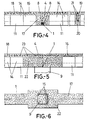
- Figure 4 shows a cross section of the central zone corresponding to the mixed flat girder according to the object of the invention.
- Figure 5 shows a cross section of the zone corresponding to the ends of the mixed flat girder also performed according to the object of the invention.
- Figure 6 shows a plan view of a detail corresponding to the reinforced concrete abacus over the supporting pillars, all of which is part of the mixed flat girder performed according to the object of the invention.
- the metal structure of the mixed flat girder which forms part of the object of the invention includes a "T" metal profile (1), although this can also be a double “T” profile, placed in an inverted position wherein the stem (2) is positioned vertically upwards while the wings (3) are arranged horizontally along the bottom.
- a series of attachment elements or so-called connectors (4) presenting an extension (5) at an end thereof which determines a foot secured by welding (6) to the upper edge of the stem (2) of profile (1), the upper end also being attached by welding (6) to a round, preferably corrugated rod which forms a hanger (7), said hanger being positioned horizontally along an upper plane.
- Figure 1 shows that the structure also includes a round strengthening rod (8) positioned over the horizontal wing (3) of profile (1), secured by electric welding both to the wing (3) and the stem (2), thereby forming a single mixed structure composite element.
- the connectors (4) are arranged in a slanting position, forming a 45° angle with the horizontal.
- this main basic structure for obtaining a mixed flat girder may allow for other ways of embodiment, such as that wherein the connectors (4) are attached at one end to a lower corrugated round rod, while the other (upper) end is attached to another round rod which forms the hanger itself, or else the connectors (4) may be attached by their lower end to partially overlapping lower corrugated round rods, thus enabling their welding along said overlapping zone, i.e. the basic profile (1) being removed in this case, as the structure is implemented in versions having a lower strength capability.
- the structure built according to Figure 1 is arranged to lean on its ends over corresponding pillars (9), being embedded therein, which pillars support the planking (10) with widened zones (10') adjacent the pillars (9), said planking being duly propped-up to further support the unidirectional semi-resistant joists (11) of a conventional or other shape or profile, Figure 3 specifically showing three types of joist (11) profiles which are complemented with corresponding strengthening structures to overcome negative bending moments (16).
- both the semi-resistant joists (11) and the corresponding end hollow brick (14) are spaced from said structure for the purposes discussed hereunder.
- the pillars (9) are fitted with corresponding structures (15) based on corrugated rods, the joists (11) also being provided with corrugated round bars or rods (16) by way of strengthening elements.
- Figure 4 shows a cross section of the central zone of the mixed flat girder obtained on-site, revealing the inverted "T" metal profile (1), the connectors (4), the hollow bricks (14), the semi-resistant joists (11) and the girder stem formed by the concrete (17) which also forms the compression layer (18) with the structure (16) based on corrugated round bars located in the upper part to overcome negative bending moments in the concrete slab and the supports of the joists (11) on the girder planking (10) which forms the reinforced concrete (17), said Figure 4 also showing the formation of reinforced concrete transversal nerves (20) with corrugated round rods (21) positioned in the upper, lower and intermediate or buttressing part.
- Figure 5 shows a cross section of the end zone of the mixed flat girder which leans on the pillars, and also shows the widening of the solidified concrete designed to form the corresponding abacus (22) structured with corrugated round rods (23) positioned in the upper part of said abacus (22), close to the girder's (17) negative bending moment influence zone.
- Figure 6 shows a detail of the reinforced concrete abacus (22) on the supporting pillars (9).
- the ends of the metal structure obtained from profile (1) are anchored to the pillars (9) in the form of embedded knot supports having a specific hyperstatic degree and being provided with an adequate abacus (22) structured with the corrugated round rods (23) placed on the upper part of said abacus (22) and in the concrete compression layer (18), which allows for continuity of the girders (17) in a manner that said corrugated round rods (23) are positioned in the abacus (22) itself adjacent the compression layer (18) and within the area of influence of the girder's (17) negative bending moments.
- the propped-up and counter-attached planking (10) and (10') is arranged to receive the support of the semi-resistant joists (11), allowing for an approximate 11 to 15 cm gap between the joist header ends, leaving a gap between the end hollow bricks (14) and gaging said joists with the hollow bricks so that the separation from the end hollow bricks (14) is at least 25 cm, thereby to form the concrete stem (17) or so-called girder itself.
- the transversal nerve wooden planking is further arranged with a conveniently propped-up 15 cm plank to form the transversal nerve (20), allowing a minimum 10 cm separation from the first or end hollow bricks (14), and is subsequently covered with the remaining hollow bricks.
- the whole assembly is thus ready for installing the structures, first the one based on the "T" profile (1), positioned in the gap between the joist (11) header ends and, naturally, in the gap established by the first or end bricks (14), subsequently arranging the structures (21) of the transversal nerve (20) and the corrugated round rod (16) structure for the joist (11) recesses, leaving the ends of said round rods leaning on a 6 or 8 mm round rod extending lengthwise over the hollow bricks (14) to finish the structure, with the corrugated round rods (23) and the abaci (22) positioned over the pillar (9) heads for overcoming the mixed girder's negative bending moments; the work being thus fully assembled and structured to start the laying of the concrete, as follows:
- the hollow bricks, the joists and the planking are sufficiently sprayed with water; the concrete laying starts at the girder (17) and nerve (20) recesses and over the semi-resistant joists (11), to a height 3 to 4 cm below the upper part of the hollow bricks (14), becoming attached to the concrete compression layer (18) - which is at least 5 cm thick - to cover the assembly simultaneously in order to achieve a monolithic condition in the mixed flat girder obtained on-site and of the concrete slab itself; water spaying is continued to achieve a good setting and curing of the reinforced concrete, the cement used for the concrete having the required volume stability to avoid cracks or fissures as a result of setting retraction.
- the concrete must have a plastic consistency, and comprise vibrated aggregates having a maximum size of 25 mm.
- gaps between the semi-resistant joist (11) header ends are advantageously in the range of 22 to 27 cm and the gap between the hollow bricks is in the range of 37 to 42 cm.
Landscapes
- Architecture (AREA)
- Engineering & Computer Science (AREA)
- Civil Engineering (AREA)
- Structural Engineering (AREA)
- Physics & Mathematics (AREA)
- Electromagnetism (AREA)
- Rod-Shaped Construction Members (AREA)
- Joining Of Building Structures In Genera (AREA)
- Road Paving Structures (AREA)
- Forms Removed On Construction Sites Or Auxiliary Members Thereof (AREA)
- Bridges Or Land Bridges (AREA)
- Forging (AREA)
- Floor Finish (AREA)
- Panels For Use In Building Construction (AREA)
Applications Claiming Priority (2)
| Application Number | Priority Date | Filing Date | Title |
|---|---|---|---|
| ES009600363A ES2132002B1 (es) | 1996-02-15 | 1996-02-15 | Mejoras en sistemas de construccion de suelos de forjados planos unidireccionales. |
| ES9600363 | 1996-02-15 |
Publications (2)
| Publication Number | Publication Date |
|---|---|
| EP0790367A1 true EP0790367A1 (fr) | 1997-08-20 |
| EP0790367B1 EP0790367B1 (fr) | 2003-05-07 |
Family
ID=8293825
Family Applications (1)
| Application Number | Title | Priority Date | Filing Date |
|---|---|---|---|
| EP97500036A Expired - Lifetime EP0790367B1 (fr) | 1996-02-15 | 1997-02-14 | Structure de poutre mixte plane réalisée sur chantier pour la construction de dalles plates unidirectionnelles en béton |
Country Status (6)
| Country | Link |
|---|---|
| EP (1) | EP0790367B1 (fr) |
| AT (1) | ATE239839T1 (fr) |
| DE (1) | DE69721606T2 (fr) |
| DK (1) | DK0790367T3 (fr) |
| ES (2) | ES2132002B1 (fr) |
| PT (1) | PT790367E (fr) |
Cited By (1)
| Publication number | Priority date | Publication date | Assignee | Title |
|---|---|---|---|---|
| US20220049495A1 (en) * | 2018-09-10 | 2022-02-17 | Hcsl Pty Ltd | Building panel |
Citations (7)
| Publication number | Priority date | Publication date | Assignee | Title |
|---|---|---|---|---|
| GB191109026A (en) * | 1911-04-11 | 1912-04-11 | Richard Gasterstadt | Improvements in Reinforced Concrete Flooring and the like. |
| FR614564A (fr) * | 1926-04-15 | 1926-12-17 | Perfectionnements dans les pièces d'armature pour la construction | |
| US2379636A (en) * | 1941-10-17 | 1945-07-03 | Robertson Co H H | Method of making reinforced concrete buildings |
| FR1220153A (fr) * | 1958-01-15 | 1960-05-23 | A V I Alpenlandische Veredelun | Poutre de construction légère |
| FR1276092A (fr) * | 1960-10-03 | 1961-11-17 | Poutres préfabriquées en métal et béton armé associés | |
| GB1158772A (en) * | 1965-03-26 | 1969-07-16 | Abraham Lipski | Process of manufacture of a Core Beam made of Reinforced Concrete and/or Pre-Stressed Concrete |
| DE2034034A1 (de) * | 1969-09-01 | 1971-03-04 | Davum, Villeneuve la Garenne (Frankreich) | Gitterträger mit praktisch drei eckigem Querschnitt |
Family Cites Families (5)
| Publication number | Priority date | Publication date | Assignee | Title |
|---|---|---|---|---|
| US1158772A (en) * | 1911-02-03 | 1915-11-02 | Cottrell C B & Sons Co | Tympan for box cutting and scoring machines. |
| US1380613A (en) * | 1916-06-22 | 1921-06-07 | Michael J Wall | Concrete-reinforcement |
| CH179365A (de) * | 1934-10-01 | 1935-09-15 | Schleutermann Max | Betonkonstruktion mit Eisentragbalken. |
| CH188249A (de) * | 1936-03-19 | 1936-12-31 | Schleutermann Max | Betondecke. |
| BE637136A (fr) * | 1960-02-03 |
-
1996
- 1996-02-15 ES ES009600363A patent/ES2132002B1/es not_active Expired - Fee Related
-
1997
- 1997-02-14 EP EP97500036A patent/EP0790367B1/fr not_active Expired - Lifetime
- 1997-02-14 DE DE69721606T patent/DE69721606T2/de not_active Expired - Fee Related
- 1997-02-14 DK DK97500036T patent/DK0790367T3/da active
- 1997-02-14 PT PT97500036T patent/PT790367E/pt unknown
- 1997-02-14 AT AT97500036T patent/ATE239839T1/de not_active IP Right Cessation
-
2000
- 2000-03-09 ES ES200000567A patent/ES2237216B1/es not_active Expired - Fee Related
Patent Citations (7)
| Publication number | Priority date | Publication date | Assignee | Title |
|---|---|---|---|---|
| GB191109026A (en) * | 1911-04-11 | 1912-04-11 | Richard Gasterstadt | Improvements in Reinforced Concrete Flooring and the like. |
| FR614564A (fr) * | 1926-04-15 | 1926-12-17 | Perfectionnements dans les pièces d'armature pour la construction | |
| US2379636A (en) * | 1941-10-17 | 1945-07-03 | Robertson Co H H | Method of making reinforced concrete buildings |
| FR1220153A (fr) * | 1958-01-15 | 1960-05-23 | A V I Alpenlandische Veredelun | Poutre de construction légère |
| FR1276092A (fr) * | 1960-10-03 | 1961-11-17 | Poutres préfabriquées en métal et béton armé associés | |
| GB1158772A (en) * | 1965-03-26 | 1969-07-16 | Abraham Lipski | Process of manufacture of a Core Beam made of Reinforced Concrete and/or Pre-Stressed Concrete |
| DE2034034A1 (de) * | 1969-09-01 | 1971-03-04 | Davum, Villeneuve la Garenne (Frankreich) | Gitterträger mit praktisch drei eckigem Querschnitt |
Cited By (1)
| Publication number | Priority date | Publication date | Assignee | Title |
|---|---|---|---|---|
| US20220049495A1 (en) * | 2018-09-10 | 2022-02-17 | Hcsl Pty Ltd | Building panel |
Also Published As
| Publication number | Publication date |
|---|---|
| EP0790367B1 (fr) | 2003-05-07 |
| DE69721606D1 (de) | 2003-06-12 |
| DK0790367T3 (da) | 2003-09-01 |
| DE69721606T2 (de) | 2004-02-19 |
| ES2132002B1 (es) | 2000-04-16 |
| PT790367E (pt) | 2003-09-30 |
| ES2132002A1 (es) | 1999-08-01 |
| ES2237216B1 (es) | 2006-06-01 |
| ES2237216A1 (es) | 2005-07-16 |
| ATE239839T1 (de) | 2003-05-15 |
Similar Documents
| Publication | Publication Date | Title |
|---|---|---|
| US9890505B2 (en) | Precast concrete beam | |
| CN106836479B (zh) | 一种装配式预应力混凝土框架结构 | |
| CA2407359C (fr) | Construction avec poutre a treillis dissymetrique | |
| CN103388357B (zh) | 耐震、预制的钢管剪力墙混合结构建筑物 | |
| US3307304A (en) | Composite structural systems | |
| EP2181224A1 (fr) | Poutres perfectionnées pour renforcer le béton et procédé pour les relier à des piliers afin de fournir une continuité d'une baie à une autre | |
| CN206707005U (zh) | 一种装配式预应力混凝土框架结构 | |
| WO2003046299A1 (fr) | Element structurel composite avec renfort structurel longitudinal | |
| CN115613439B (zh) | 一种超轻型组合梁桥及其施工方法 | |
| CN108149643A (zh) | 碾压混凝土双曲拱坝双向可调翻升模板及施工方法 | |
| US5121518A (en) | Cable-stayed bridge and construction process | |
| EP1132538A2 (fr) | Plaque prefabriquee autoporteuse de polystyrene | |
| CN106545115B (zh) | 装配式钢-混凝土组合楼盖的施工方法 | |
| RU2233952C1 (ru) | Каркас многоэтажного здания | |
| CN115573501B (zh) | 一种装配式坡面屋顶 | |
| KR20160115602A (ko) | 교량 바닥판의 교체 방법 및 이에 사용되는 프리스트레스트 콘크리트 거더 조립체 | |
| CA2932655C (fr) | Poutre en beton precoule | |
| CN110392758B (zh) | 倒t形截面混合型预应力混凝土梁及利用其的面板施工方法 | |
| EP0790367B1 (fr) | Structure de poutre mixte plane réalisée sur chantier pour la construction de dalles plates unidirectionnelles en béton | |
| KR20200100730A (ko) | 착탈식 바닥 구조 | |
| CN107268852B (zh) | 一种预制槽板构成的楼板结构的施工方法 | |
| CN114635503A (zh) | 一种与混凝土框架柱柔性连接的清水混凝土墙及施工方法 | |
| CN109137757A (zh) | 一种大跨度波形钢腹板箱梁抗屈曲结构及施工方法 | |
| CN220414636U (zh) | 一种压型钢板混凝土组合楼板 | |
| CN215563720U (zh) | 一种预制叠合板结构 |
Legal Events
| Date | Code | Title | Description |
|---|---|---|---|
| PUAI | Public reference made under article 153(3) epc to a published international application that has entered the european phase |
Free format text: ORIGINAL CODE: 0009012 |
|
| AK | Designated contracting states |
Kind code of ref document: A1 Designated state(s): AT BE DE DK FI FR GB GR IE IT LU NL PT SE |
|
| 17P | Request for examination filed |
Effective date: 19980122 |
|
| 17Q | First examination report despatched |
Effective date: 19990921 |
|
| GRAH | Despatch of communication of intention to grant a patent |
Free format text: ORIGINAL CODE: EPIDOS IGRA |
|
| RTI1 | Title (correction) |
Free format text: ON-SITE MIXED FLAT COMPOSITE GIRDER STRUCTURE FOR UNIDIRECTIONAL FLAT CONCRETE FLOORING CONSTRUCTION |
|
| GRAH | Despatch of communication of intention to grant a patent |
Free format text: ORIGINAL CODE: EPIDOS IGRA |
|
| GRAA | (expected) grant |
Free format text: ORIGINAL CODE: 0009210 |
|
| AK | Designated contracting states |
Designated state(s): AT BE DE DK FI FR GB GR IE IT LU NL PT SE |
|
| REG | Reference to a national code |
Ref country code: GB Ref legal event code: FG4D |
|
| REG | Reference to a national code |
Ref country code: IE Ref legal event code: FG4D |
|
| REF | Corresponds to: |
Ref document number: 69721606 Country of ref document: DE Date of ref document: 20030612 Kind code of ref document: P |
|
| REG | Reference to a national code |
Ref country code: SE Ref legal event code: TRGR |
|
| REG | Reference to a national code |
Ref country code: DK Ref legal event code: T3 |
|
| REG | Reference to a national code |
Ref country code: GR Ref legal event code: EP Ref document number: 20030403093 Country of ref document: GR |
|
| REG | Reference to a national code |
Ref country code: PT Ref legal event code: SC4A Free format text: AVAILABILITY OF NATIONAL TRANSLATION Effective date: 20030805 |
|
| PGFP | Annual fee paid to national office [announced via postgrant information from national office to epo] |
Ref country code: DK Payment date: 20040123 Year of fee payment: 8 |
|
| PGFP | Annual fee paid to national office [announced via postgrant information from national office to epo] |
Ref country code: PT Payment date: 20040209 Year of fee payment: 8 |
|
| PGFP | Annual fee paid to national office [announced via postgrant information from national office to epo] |
Ref country code: IE Payment date: 20040210 Year of fee payment: 8 |
|
| PGFP | Annual fee paid to national office [announced via postgrant information from national office to epo] |
Ref country code: LU Payment date: 20040211 Year of fee payment: 8 |
|
| PGFP | Annual fee paid to national office [announced via postgrant information from national office to epo] |
Ref country code: FI Payment date: 20040212 Year of fee payment: 8 |
|
| PGFP | Annual fee paid to national office [announced via postgrant information from national office to epo] |
Ref country code: SE Payment date: 20040216 Year of fee payment: 8 |
|
| PGFP | Annual fee paid to national office [announced via postgrant information from national office to epo] |
Ref country code: GB Payment date: 20040218 Year of fee payment: 8 Ref country code: BE Payment date: 20040218 Year of fee payment: 8 |
|
| PGFP | Annual fee paid to national office [announced via postgrant information from national office to epo] |
Ref country code: FR Payment date: 20040219 Year of fee payment: 8 |
|
| PGFP | Annual fee paid to national office [announced via postgrant information from national office to epo] |
Ref country code: AT Payment date: 20040223 Year of fee payment: 8 |
|
| PGFP | Annual fee paid to national office [announced via postgrant information from national office to epo] |
Ref country code: NL Payment date: 20040226 Year of fee payment: 8 |
|
| PGFP | Annual fee paid to national office [announced via postgrant information from national office to epo] |
Ref country code: DE Payment date: 20040304 Year of fee payment: 8 |
|
| ET | Fr: translation filed | ||
| PLBE | No opposition filed within time limit |
Free format text: ORIGINAL CODE: 0009261 |
|
| STAA | Information on the status of an ep patent application or granted ep patent |
Free format text: STATUS: NO OPPOSITION FILED WITHIN TIME LIMIT |
|
| 26N | No opposition filed |
Effective date: 20040210 |
|
| PG25 | Lapsed in a contracting state [announced via postgrant information from national office to epo] |
Ref country code: GR Free format text: LAPSE BECAUSE OF NON-PAYMENT OF DUE FEES Effective date: 20040903 |
|
| PG25 | Lapsed in a contracting state [announced via postgrant information from national office to epo] |
Ref country code: LU Free format text: LAPSE BECAUSE OF NON-PAYMENT OF DUE FEES Effective date: 20050214 Ref country code: IT Free format text: LAPSE BECAUSE OF NON-PAYMENT OF DUE FEES Effective date: 20050214 Ref country code: IE Free format text: LAPSE BECAUSE OF NON-PAYMENT OF DUE FEES Effective date: 20050214 Ref country code: GB Free format text: LAPSE BECAUSE OF NON-PAYMENT OF DUE FEES Effective date: 20050214 Ref country code: AT Free format text: LAPSE BECAUSE OF NON-PAYMENT OF DUE FEES Effective date: 20050214 |
|
| PG25 | Lapsed in a contracting state [announced via postgrant information from national office to epo] |
Ref country code: SE Free format text: LAPSE BECAUSE OF NON-PAYMENT OF DUE FEES Effective date: 20050215 |
|
| PGFP | Annual fee paid to national office [announced via postgrant information from national office to epo] |
Ref country code: GR Payment date: 20050215 Year of fee payment: 9 |
|
| PG25 | Lapsed in a contracting state [announced via postgrant information from national office to epo] |
Ref country code: DK Free format text: LAPSE BECAUSE OF NON-PAYMENT OF DUE FEES Effective date: 20050228 Ref country code: BE Free format text: LAPSE BECAUSE OF NON-PAYMENT OF DUE FEES Effective date: 20050228 |
|
| PG25 | Lapsed in a contracting state [announced via postgrant information from national office to epo] |
Ref country code: PT Free format text: LAPSE BECAUSE OF NON-PAYMENT OF DUE FEES Effective date: 20050816 |
|
| BERE | Be: lapsed |
Owner name: *MIMENZA LARRACOECHEA RAMON Effective date: 20050228 |
|
| PG25 | Lapsed in a contracting state [announced via postgrant information from national office to epo] |
Ref country code: NL Free format text: LAPSE BECAUSE OF NON-PAYMENT OF DUE FEES Effective date: 20050901 Ref country code: DE Free format text: LAPSE BECAUSE OF NON-PAYMENT OF DUE FEES Effective date: 20050901 |
|
| REG | Reference to a national code |
Ref country code: DK Ref legal event code: EBP |
|
| EUG | Se: european patent has lapsed | ||
| GBPC | Gb: european patent ceased through non-payment of renewal fee |
Effective date: 20050214 |
|
| PG25 | Lapsed in a contracting state [announced via postgrant information from national office to epo] |
Ref country code: FR Free format text: LAPSE BECAUSE OF NON-PAYMENT OF DUE FEES Effective date: 20051031 |
|
| REG | Reference to a national code |
Ref country code: PT Ref legal event code: MM4A Effective date: 20050816 |
|
| NLV4 | Nl: lapsed or anulled due to non-payment of the annual fee |
Effective date: 20050901 |
|
| REG | Reference to a national code |
Ref country code: IE Ref legal event code: MM4A |
|
| REG | Reference to a national code |
Ref country code: FR Ref legal event code: ST Effective date: 20051031 |
|
| BERE | Be: lapsed |
Owner name: *MIMENZA LARRACOECHEA RAMON Effective date: 20050228 |