EP0790404A1 - Dispositif d'injection directe de combustible et moteur à combustion interne équipé du dit dispositif - Google Patents
Dispositif d'injection directe de combustible et moteur à combustion interne équipé du dit dispositif Download PDFInfo
- Publication number
- EP0790404A1 EP0790404A1 EP97102258A EP97102258A EP0790404A1 EP 0790404 A1 EP0790404 A1 EP 0790404A1 EP 97102258 A EP97102258 A EP 97102258A EP 97102258 A EP97102258 A EP 97102258A EP 0790404 A1 EP0790404 A1 EP 0790404A1
- Authority
- EP
- European Patent Office
- Prior art keywords
- fuel
- cylinder
- opening
- fuel injection
- injection device
- Prior art date
- Legal status (The legal status is an assumption and is not a legal conclusion. Google has not performed a legal analysis and makes no representation as to the accuracy of the status listed.)
- Granted
Links
Images


Classifications
-
- F—MECHANICAL ENGINEERING; LIGHTING; HEATING; WEAPONS; BLASTING
- F02—COMBUSTION ENGINES; HOT-GAS OR COMBUSTION-PRODUCT ENGINE PLANTS
- F02M—SUPPLYING COMBUSTION ENGINES IN GENERAL WITH COMBUSTIBLE MIXTURES OR CONSTITUENTS THEREOF
- F02M61/00—Fuel-injectors not provided for in groups F02M39/00 - F02M57/00 or F02M67/00
- F02M61/16—Details not provided for in, or of interest apart from, the apparatus of groups F02M61/02 - F02M61/14
- F02M61/18—Injection nozzles, e.g. having valve seats; Details of valve member seated ends, not otherwise provided for
- F02M61/188—Spherical or partly spherical shaped valve member ends
-
- F—MECHANICAL ENGINEERING; LIGHTING; HEATING; WEAPONS; BLASTING
- F02—COMBUSTION ENGINES; HOT-GAS OR COMBUSTION-PRODUCT ENGINE PLANTS
- F02M—SUPPLYING COMBUSTION ENGINES IN GENERAL WITH COMBUSTIBLE MIXTURES OR CONSTITUENTS THEREOF
- F02M61/00—Fuel-injectors not provided for in groups F02M39/00 - F02M57/00 or F02M67/00
- F02M61/04—Fuel-injectors not provided for in groups F02M39/00 - F02M57/00 or F02M67/00 having valves, e.g. having a plurality of valves in series
- F02M61/08—Fuel-injectors not provided for in groups F02M39/00 - F02M57/00 or F02M67/00 having valves, e.g. having a plurality of valves in series the valves opening in direction of fuel flow
-
- F—MECHANICAL ENGINEERING; LIGHTING; HEATING; WEAPONS; BLASTING
- F02—COMBUSTION ENGINES; HOT-GAS OR COMBUSTION-PRODUCT ENGINE PLANTS
- F02M—SUPPLYING COMBUSTION ENGINES IN GENERAL WITH COMBUSTIBLE MIXTURES OR CONSTITUENTS THEREOF
- F02M51/00—Fuel-injection apparatus characterised by being operated electrically
- F02M51/06—Injectors peculiar thereto with means directly operating the valve needle
- F02M51/061—Injectors peculiar thereto with means directly operating the valve needle using electromagnetic operating means
- F02M51/0625—Injectors peculiar thereto with means directly operating the valve needle using electromagnetic operating means characterised by arrangement of mobile armatures
- F02M51/0664—Injectors peculiar thereto with means directly operating the valve needle using electromagnetic operating means characterised by arrangement of mobile armatures having a cylindrically or partly cylindrically shaped armature, e.g. entering the winding; having a plate-shaped or undulated armature entering the winding
- F02M51/0671—Injectors peculiar thereto with means directly operating the valve needle using electromagnetic operating means characterised by arrangement of mobile armatures having a cylindrically or partly cylindrically shaped armature, e.g. entering the winding; having a plate-shaped or undulated armature entering the winding the armature having an elongated valve body attached thereto
-
- F—MECHANICAL ENGINEERING; LIGHTING; HEATING; WEAPONS; BLASTING
- F02—COMBUSTION ENGINES; HOT-GAS OR COMBUSTION-PRODUCT ENGINE PLANTS
- F02M—SUPPLYING COMBUSTION ENGINES IN GENERAL WITH COMBUSTIBLE MIXTURES OR CONSTITUENTS THEREOF
- F02M53/00—Fuel-injection apparatus characterised by having heating, cooling or thermally-insulating means
- F02M53/04—Injectors with heating, cooling, or thermally-insulating means
-
- F—MECHANICAL ENGINEERING; LIGHTING; HEATING; WEAPONS; BLASTING
- F02—COMBUSTION ENGINES; HOT-GAS OR COMBUSTION-PRODUCT ENGINE PLANTS
- F02M—SUPPLYING COMBUSTION ENGINES IN GENERAL WITH COMBUSTIBLE MIXTURES OR CONSTITUENTS THEREOF
- F02M61/00—Fuel-injectors not provided for in groups F02M39/00 - F02M57/00 or F02M67/00
- F02M61/16—Details not provided for in, or of interest apart from, the apparatus of groups F02M61/02 - F02M61/14
- F02M61/162—Means to impart a whirling motion to fuel upstream or near discharging orifices
-
- F—MECHANICAL ENGINEERING; LIGHTING; HEATING; WEAPONS; BLASTING
- F02—COMBUSTION ENGINES; HOT-GAS OR COMBUSTION-PRODUCT ENGINE PLANTS
- F02M—SUPPLYING COMBUSTION ENGINES IN GENERAL WITH COMBUSTIBLE MIXTURES OR CONSTITUENTS THEREOF
- F02M61/00—Fuel-injectors not provided for in groups F02M39/00 - F02M57/00 or F02M67/00
- F02M61/16—Details not provided for in, or of interest apart from, the apparatus of groups F02M61/02 - F02M61/14
- F02M61/18—Injection nozzles, e.g. having valve seats; Details of valve member seated ends, not otherwise provided for
-
- F—MECHANICAL ENGINEERING; LIGHTING; HEATING; WEAPONS; BLASTING
- F02—COMBUSTION ENGINES; HOT-GAS OR COMBUSTION-PRODUCT ENGINE PLANTS
- F02M—SUPPLYING COMBUSTION ENGINES IN GENERAL WITH COMBUSTIBLE MIXTURES OR CONSTITUENTS THEREOF
- F02M65/00—Testing fuel-injection apparatus, e.g. testing injection timing ; Cleaning of fuel-injection apparatus
- F02M65/007—Cleaning
- F02M65/008—Cleaning of injectors only
-
- F—MECHANICAL ENGINEERING; LIGHTING; HEATING; WEAPONS; BLASTING
- F02—COMBUSTION ENGINES; HOT-GAS OR COMBUSTION-PRODUCT ENGINE PLANTS
- F02M—SUPPLYING COMBUSTION ENGINES IN GENERAL WITH COMBUSTIBLE MIXTURES OR CONSTITUENTS THEREOF
- F02M69/00—Low-pressure fuel-injection apparatus ; Apparatus with both continuous and intermittent injection; Apparatus injecting different types of fuel
- F02M69/04—Injectors peculiar thereto
- F02M69/042—Positioning of injectors with respect to engine, e.g. in the air intake conduit
- F02M69/045—Positioning of injectors with respect to engine, e.g. in the air intake conduit for injecting into the combustion chamber
-
- F—MECHANICAL ENGINEERING; LIGHTING; HEATING; WEAPONS; BLASTING
- F02—COMBUSTION ENGINES; HOT-GAS OR COMBUSTION-PRODUCT ENGINE PLANTS
- F02M—SUPPLYING COMBUSTION ENGINES IN GENERAL WITH COMBUSTIBLE MIXTURES OR CONSTITUENTS THEREOF
- F02M69/00—Low-pressure fuel-injection apparatus ; Apparatus with both continuous and intermittent injection; Apparatus injecting different types of fuel
- F02M69/04—Injectors peculiar thereto
- F02M69/047—Injectors peculiar thereto injectors with air chambers, e.g. communicating with atmosphere for aerating the nozzles
-
- F—MECHANICAL ENGINEERING; LIGHTING; HEATING; WEAPONS; BLASTING
- F02—COMBUSTION ENGINES; HOT-GAS OR COMBUSTION-PRODUCT ENGINE PLANTS
- F02B—INTERNAL-COMBUSTION PISTON ENGINES; COMBUSTION ENGINES IN GENERAL
- F02B75/00—Other engines
- F02B75/12—Other methods of operation
- F02B2075/125—Direct injection in the combustion chamber for spark ignition engines, i.e. not in pre-combustion chamber
-
- Y—GENERAL TAGGING OF NEW TECHNOLOGICAL DEVELOPMENTS; GENERAL TAGGING OF CROSS-SECTIONAL TECHNOLOGIES SPANNING OVER SEVERAL SECTIONS OF THE IPC; TECHNICAL SUBJECTS COVERED BY FORMER USPC CROSS-REFERENCE ART COLLECTIONS [XRACs] AND DIGESTS
- Y02—TECHNOLOGIES OR APPLICATIONS FOR MITIGATION OR ADAPTATION AGAINST CLIMATE CHANGE
- Y02T—CLIMATE CHANGE MITIGATION TECHNOLOGIES RELATED TO TRANSPORTATION
- Y02T10/00—Road transport of goods or passengers
- Y02T10/10—Internal combustion engine [ICE] based vehicles
- Y02T10/12—Improving ICE efficiencies
-
- Y—GENERAL TAGGING OF NEW TECHNOLOGICAL DEVELOPMENTS; GENERAL TAGGING OF CROSS-SECTIONAL TECHNOLOGIES SPANNING OVER SEVERAL SECTIONS OF THE IPC; TECHNICAL SUBJECTS COVERED BY FORMER USPC CROSS-REFERENCE ART COLLECTIONS [XRACs] AND DIGESTS
- Y10—TECHNICAL SUBJECTS COVERED BY FORMER USPC
- Y10S—TECHNICAL SUBJECTS COVERED BY FORMER USPC CROSS-REFERENCE ART COLLECTIONS [XRACs] AND DIGESTS
- Y10S239/00—Fluid sprinkling, spraying, and diffusing
- Y10S239/19—Nozzle materials
Definitions
- the present invention relates to an internal combustion engine of in-cylinder fuel injection type ion which gasoline is directly injected into a combustion chamber, and more particularly to a fuel injection valve of electromagnetic type for directly injecting fuel into a combustion chamber.
- the electromagnetic fuel injection valve is installed near the air-intake valve in the cylinder head, temperature of the cylinder head of the gasoline engine becomes 250 to 300 °C during operation of the engine. Therefore, the front end portion of the electromagnetic fuel injection valve is also heated up to near the same temperature. Under such a temperature condition, it is accelerated to produce deposits of carbonization-growing materials of the injected gasoline and a mixture of engine lubricant and the gasoline. Most of the deposits are amorphous flakes. However, when the temperature is increased, the carbonization is further progressed to form soot of a grain structure having a size of several tens nano-meters. The deposits and the soot attaches and accumulates onto the wall surface of the combustion chamber and the valve front portion of the electromagnetic fuel injection valve.
- Japanese 'Patent Application Laid-Open No.3-225068 proposes that an externally opening valve is employed and ring-shaped projections projecting outward are provided in the peripheral portion of the front end of the valve head and in the peripheral portion of an opening of the fuel injection nozzle of the valve body. By doing so, appropriate fuel injection is performed by that the projections concentratively receive heat from the engine compared to the other parts and the temperature of the projection is locally increased to suppress formation of deposits due to the attached fuel drops.
- Japanese Patent Application Laid-Open No.6-147022 discloses a fuel injection device for directly injecting fuel into a combustion chamber in which exhaust gas is recirculated in order to decrease NO x exhaust.
- the deposits and the soot attached onto the wall surface of the combustion chamber are not considered as a problem since they increase the thermal insulating efficiency to improve the combustion efficiency.
- the deposits are attached and accumulated at the valve front portion of the electromagnetic fuel injection valve, particularly near the fuel injection nozzle and at an inside portion of the fuel injection nozzle provided at the front end portion of the electromagnetic fuel injection valve, the injecting direction and the fuel spray shape are changed and the fuel mist particle size becomes large. Therefore, the engine is exerted not only a bad influence on combustion, but the fuel injection nozzle is choked and the injection resistance is increased. As the result, a desired amount of fuel injection cannot be injected. In a worst case, it is concerned that fuel cannot be injected and consequently the cannot be operated.
- the inventors of the present invention have been experimentally studied on an in-cylinder fuel injection device capable of applying to a gasoline engine with taking the results of the conventional technology into consideration. As a result, the following are revealed.
- the spread angle of fuel spray particles is set to 60° to 90° . Further, it has been found that there is a appropriate angle range in the spread angle of fuel spray particles depending on an operating condition of the engine.
- the spread angle of fuel spray particles is suppressed small, namely nearly 60° , to form a good flammable condition when temperature of the wall surface is low such as at starting time, and the spread angle of fuel spray particles is widened, namely nearly 90° , to disperse the mixture of fuel and air and to decrease a generating amount of soot by suppressing local red-flame burning when combustion is progressed and the temperature of the wall surface becomes high.
- an object of the present invention to solve the aforementioned problems in the prior art is to prevent deposits and soot from attaching and accumulating onto the vicinity of the injection nozzle and to lessen time varying degradation in the performance of the fuel injection valve.
- another object of the present invention is to maintain normal operation of the internal combustion engine.
- a further object of the present invention is to provide an electromagnetic fuel injection device capable of directly injecting fuel in a combustion chamber which is low in cost and long in life.
- a still further object of the present invention is to provide an electromagnetic fuel injection valve capable of directly injecting fuel in a combustion chamber which can continue atomizing fuel for a long time.
- a still further object of the present invention is to maintain normal operation.
- a further object of the present invention is to provide a fuel injection device and an internal combustion engine mounting the fuel injection device which can accurately measure a fuel flow rate necessary for the internal engine even when deposits and soot are attached onto the fuel injection device.
- a first embodiment of the present invention to attain the above objects is an in-cylinder fuel injection device for directly injecting fuel into an combustion chamber of an internal combustion engine in which a fuel passage for passing fuel is formed, wherein the in-cylinder fuel injection device further comprises a valve member for opening and closing the fuel passage, a fuel swirl member for giving swirl to fuel provided in the upstream side of an opening and closing portion of the valve member, a fuel injecting hole member having a through hole for passing fuel provided in the downstream side of the opening and closing portion, and a cover member for covering the fuel injecting hole member having an injecting hole and made of a high thermal conductive material.
- the cover member is made of any one of a brass and an aluminum alloy. It is also preferable that the cover member has at least one concave portion at a contact surface side with the fuel injection member. Further, it is preferable that surface temperature near the injecting hole of the cover member is raised to a temperature from 550°C to 1050°C during operation of the internal combustion engine.
- a second embodiment of the present invention to attain the above objects is an in-cylinder fuel infection device for directly injecting fuel into an combustion chamber of an internal combustion engine in which a fuel passage for passing fuel is formed, wherein the in-cylinder fuel injection device further comprises a valve member for opening and closing the fuel passage, a fuel swirl member for giving swirl to fuel provided in the upstream side of an opening and closing portion of the valve member, a fuel injecting hole member having a through hole for passing fuel provided in the downstream side of the opening and closing portion, and the fuel injection member has a thermal conductance improving member for improving thermal conductance to the side facing the combustion chamber of the internal combustion engine.
- the thermal conductance improving member is a member for increasing a surface area thereof by providing projections or depressions. It is also preferable that the thermal conductance improving member is a surface vapor-deposited layer for increasing thermal conductance.
- a third embodiment of the present invention to attain the above objects is an in-cylinder fuel injection device for directly injecting fuel into an combustion chamber of an internal combustion engine in which a fuel passage for passing fuel is formed, wherein the in-cylinder fuel injection device further comprises a valve member for opening and closing the fuel passage, a fuel swirl member for giving swirl to fuel provided in the upstream side of an opening and closing portion of the valve member, a fuel injecting hole member having a through hole for passing fuel provided in the downstream side of the opening and closing portion, a cover member for covering the fuel injecting hole member having an injecting hole made of a high thermal conductive material, and a thermal convection preventing means for preventing thermal convection from the cover member to the fuel injecting hole member provided between the cover member and the fuel injecting hole member.
- distance in the axial direction of the narrowest portion of the through hole provided in the fuel injecting hole member is within the range of 0.1 to 0.4 mm.
- a third embodiment of the present invention to attain the above objects is an in-cylinder fuel injection device for directly injecting fuel into an combustion chamber of an internal combustion engine in which a fuel passage for passing fuel is formed, wherein the in-cylinder fuel injection device further comprises a valve member for opening and closing the fuel passage, a fuel swirl member for giving swirl to fuel provided in the upstream side of an opening and closing portion of the valve member, a fuel injecting hole member having a through hole for passing fuel provided in the downstream side of the opening and closing portion, and an amount of fuel to be injected into the internal combustion engine is measured in the opening and closing portion of said valve member.
- a fifth embodiment of the present invention is an in-cylinder fuel injection device for directly injecting fuel into an combustion chamber of an internal combustion engine in which a fuel passage for passing fuel is formed
- the in-cylinder fuel injection device comprises a ball valve member for opening and closing the fuel passage, a fuel swirl member for giving swirl to fuel provided in the upstream side of an opening and closing portion of the ball valve member, a through hole member having a through hole for passing fuel provided in the downstream side of the opening and closing portion, and a cover member for covering the through hole member having a fuel injecting hole in the center thereof, and an opening flow passage area (SV) of the opening and closing portion of the ball valve member and a flow passage area (SO) of the fuel injecting hole formed in the cover member satisfy relationship of SV ⁇ SO.
- the in-cylinder fuel injection device includes an electromagnetic type fuel injection device.
- a sixth embodiment of the present invention to attain the above objects is an internal combustion engine comprising a cylinder, a cylinder head for covering an upper portion of the cylinder, an intake manifold forming an intake air passage for guiding intake air provided in the cylinder head, an exhaust manifold forming an exhaust gas passage for guiding exhaust gas provided in the cylinder head, an intake valve for choking the intake air passage, an exhaust valve for choking the exhaust gas passage, and a spark plug, wherein a fuel injection device for directly injecting fuel into a combustion chamber formed by the cylinder head and the cylinder is provided, and the fuel injection device comprises a fuel flow passage for passing fuel inside, a valve member for opening and closing the fuel passage, a fuel swirl member for giving swirl to fuel provided in the upstream side of an opening and closing portion of the valve member, a fuel injecting hole member having a through hole for passing fuel provided in the downstream side of the opening and closing portion, and a cover member for covering the fuel injecting hole member and made of either a brass or an aluminum alloy.
- a seventh embodiment of the present invention is an internal combustion engine comprising a cylinder, a cylinder head for covering an upper portion of the cylinder, an intake manifold forming an intake air passage for guiding intake air provided in the cylinder head, an exhaust manifold forming an exhaust gas passage for guiding exhaust gas provided in the cylinder head, an intake valve for choking the intake air passage, an exhaust valve for choking the exhaust gas passage, and a spark plug, wherein a fuel injection device for directly injecting fuel into a combustion chamber formed by the cylinder head and the cylinder is provided, and the fuel injection device comprises a fuel flow passage for passing fuel inside, a valve member for opening and closing the fuel passage, a fuel swirl member for giving swirl to fuel provided in the upstream side of an opening and closing portion of the valve member, a fuel injecting hole member having a through hole for passing fuel provided in the downstream side of the opening and closing portion, and a cover member for covering the fuel injecting hole member and made of either of a brass or an aluminum alloy, and a
- an eighth embodiment of the present invention is an internal combustion engine comprising a cylinder, a cylinder head for covering an upper portion of the cylinder, an intake manifold forming an intake air passage for guiding intake air provided in the cylinder head, an exhaust manifold forming an exhaust gas passage for guiding exhaust gas provided into the cylinder head, an intake valve for choking the intake air passage, an exhaust valve for choking the exhaust gas passage, and a spark plug, wherein a fuel injection device for directly injecting fuel into a combustion chamber formed by the cylinder head and the cylinder is provided, and the fuel injection device comprises a fuel flow passage for passing fuel inside, a ball valve member for opening and closing the fuel passage, a fuel swirl member for giving swirl to fuel provided in the upstream side of an opening and closing portion of the ball valve member, a through hole member having a through hole for passing fuel provided in the downstream side of the opening and closing portion, and a cover member for covering said through hole member in the center thereof, wherein an opening flow passage area (SV) of the opening and closing
- the cover member including the fuel injecting hole is heated with combustion heat up to the cleaning temperature of deposits, and consequently it is possible to prevent deposits and soot changed from the deposits from attaching and accumulating onto the top end portion of the electromagnetic fuel injection valve.
- an electromagnetic fuel injection valve capable of directly injecting fuel into the combustion chamber, it is possible to prevent deposits and soot from attaching and accumulating onto the surrounding of the injecting hole and to decrease time varying degradation of the performance.
- an electromagnetic fuel injection device capable of directly injecting fuel into the combustion chamber which is low in cost and long in life time.
- an electromagnetic fuel injection valve capable of directly injecting fuel into the combustion chamber which can continue atomization of fuel for a long time.
- an internal combustion engine mounting an electromagnetic fuel injection valve capable of directly injecting fuel into the combustion chamber which can maintain normal operation.
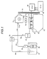
- FIG.1 is a schematic diagram showing the system construction of an internal combustion engine of in-cylinder fuel injection type in which fuel is directly injected into the combustion chamber in accordance with the present invention.
- FIG.2 is an enlarged view of an engine in the system of FIG.1.
- FIG.3 is a vertical cross-sectional view showing an embodiment of an in-cylinder fuel injection device in accordance with the present invention.
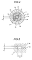
- FIG.4 is a detailed view showing a fuel swirl member taking the cross-sectional plane of the line A-A of FIG.3.
- FIG.5 is a detailed cross-sectional view showing a swirl groove of a fuel swirl member.
- FIG.6 is an enlarged vertical cross-sectional view showing an embodiment of a valve of an in-cylinder fuel injection device in accordance with the present invention.
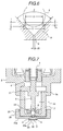
- FIG.7 is an enlarged vertical view showing an embodiment of a top end portion of an in-cylinder fuel injection device in accordance with the present invention.
- FIG.8 is an enlarged vertical view showing another embodiment of a top end portion of an in-cylinder fuel injection device in accordance with the present invention.
- FIG.9 is an enlarged vertical view showing a modified embodiment of a top end portion of an in-cylinder fuel injection device in accordance with the present invention.
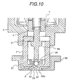
- FIG.10 is an enlarged vertical view showing a further embodiment of a top end portion of an in-cylinder fuel injection device in accordance with the present invention.
- FIG.11 is a view showing a state mounting the in-cylinder fuel injection device in the system of FIG.1.
- FIG.1 and FIG.2 show the system construction of an internal combustion engine having an embodiment of an electromagnetic fuel injection valve in accordance with the present invention which is capable of directly injecting fuel into the combustion chamber.
- a four-cylinder four-cycle gasoline engine 70 is connected to a high pressure fuel pump 71 through a belt 72.
- the high pressure fuel pump 71 is a mechanism to obtain a high pressure fuel by pressurizing fuel by cam driving, for example, by driving a piston to pressurize fuel, and has a delivery port 71a and a suction port 71b.
- the delivery port 71a and a fuel gallery 75 are connected with a high pressure pipe 73, and an accumulator 74 is arranged in the middle of the high pressure pipe 73.
- In-cylinder fuel injection devices 76 to be described later are arrayed and fixed onto the fuel gallery 75.
- a high pressure regulator 77 for maintaining pressure of the fuel supplied to the in-cylinder fuel injection devices 76 is arranged in the downstream side of the fuel gallery 75, and the surplus fuel is guided from the fuel gallery 77 to a low pressure regulator 79 through a low pressure pipe 78 and returned to a fuel tank 81 through a returning pipe 84 connected to the low pressure regulator 79.
- a low pressure fuel pump 80 is installed inside the fuel tank 81 and connected to the suction side of the high pressure fuel pump 71 through a filter 82 and a low pressure pipe 83. An excessive part of the fuel supplied from the low pressure fuel pump 80 to the high pressure fuel pump 71 is guided to the low pressure regulator 79 through a branch pipe provided in the middle of the low pressure pipe 83 and returned to the fuel tank 81 through the returning pipe 84.
- Number of the in-cylinder fuel injection devices 76 corresponds to the number of cylinders.
- a driver circuit 85 for controlling the in-cylinder fuel injection device 76 is connected to an engine control unit 86, and controls a fuel flow rate supplied to each of the in-cylinder fuel injection devices 76 corresponding to various commands from the engine control unit 86.
- the control unit 86 controls the engine 70 based on operating information such as a intake air flow rate, air temperature, engine water temperature, engine speed and so on.
- the internal combustion engine 70 constructed as described above will be described in detail, referring to FIG.2.
- a piston 95 reciprocally movable inside the cylinder 94 moves upward and downward in the cylinder 94 according to rotation of the engine shaft, not shown.
- a cylinder head is attached in the upper portion of the cylinder 94 to form a closed space together with the cylinder 94.
- an intake manifold 88 for introducing external air into the cylinder through an intake air flow rate control unit containing a throttle valve and an exhaust manifold for conducting combustion gas burned inside the cylinder 94.
- an intake valve 90 in the side of the intake manifold 87 there are provided an intake valve 90 in the side of the intake manifold 87, a spark plug 91 in the center and an exhaust valve 92 in the side opposite to the intake valve 90. Dish portions 90a, 92a provided in the intake valve 90 and the exhaust valve 92 are extended into the combustion chamber 96.
- An in-cylinder fuel injection device 76 in accordance with the present invention is attached to the cylinder head near the junction portion of the intake manifold 87, and set so that the direction of injecting fuel becomes slightly downward in the combustion chamber 96.
- an intake air introducing passage 93 for supplying a part of intake air to the in-cylinder fuel injection device 76.
- Fuel for the internal combustion engine 70 is directly injected into the combustion chamber 96 by the in-cylinder fuel injection device 76 in synchronism with intake air timing.
- the fuel atomized by injection is promoted to be mixed with the air introduced through the intake manifold 88, compressed in the compression stroke and then fired by the spark plug 91 to be burned.
- FIG.3 shows an embodiment of an electromagnetic fuel injection valve composing the fuel injection device 76.
- the electromagnetic fuel injection valve 1 controls fuel injection by opening and closing a sheet portion formed between a ball valve 6 and a nozzle member 7 corresponding to an ON-OFF signal of duty calculated and obtained in the control unit.
- a magnetic circuit is composed of a cylindrical yoke 3 with bottom, a core 2 and a plunger 4 facing the core 2 with a gap, and the core 2 is composed of a plug body portion 2a for closing an opening end of the yoke 3 and a column portion 2b extending in the center of the yoke 3. There is formed a hole in the center of the column portion 2b.
- a spring 10 of an elastic member which presses a movable portion 4a composed of the plunger 4 and a ball valve 6 against sheet face 9 formed in the upper surface of a nozzle member.
- the nozzle member 7 has a hole 8 for passing fuel in a position inner side of the contact portion of the ball valve 6.
- the upper end portion of the spring 10 is in contact with the lower end portion of a spring adjuster 11 for adjusting opening and closing force of the ball valve, and the spring adjuster 11 is inserted in the center of the core 2.
- an O-ring 12 is provided between the both.
- a coil 14 for exiting the magnetic circuit is wound around a bobbin 13, and the periphery is molded with a plastic material.
- a terminal 18 of a coil assembly 16 having the core 2, the coil 3 and the bobbin 13 is inserted into a hole 17 provided in a brim portion of the core 2, and an O-ring 19 is interposed between the terminal 18 and the core 2.
- a plunger receiving portion 20 engaging with the plunger 4 is bored near the lower end portion of the yoke 3, and under the plunger receiving portion a nozzle receiving portion 22 having a larger diameter than the plunger receiving portion 20 and engaging with a stopper 21 and a nozzle member 7 is formed in penetrating up to the top end of the yoke.
- a movable portion 4a comprises a plunger 4 made of a magnetic material, a rod 5 jointed to the plunger 4 in one end and a pole 6 in the other end, and a guide ring 23 fixed to the upper opening portion of the plunger 4 and made of a non-magnetic material. Further, a cylindrical fuel swirl element 26 is inserted into an inner wall of the hollow portion of the nozzle member 7. The guide ring 23 is guided with an inner wall of a hollow portion bored in the top end of the core 2, and the ball 6 is guided with the inner peripheral surface 27 of the fuel swirl element 26. In the nozzle member 7, the sheet surface 9 is formed following to the cylindrical fuel swirl element 26, and an opening 8 is provided in the center of the sheet surface 9 so that fuel can flow through.
- a stroke (upward moving amount in the axial direction) of the movable portion 4a is determined by the dimension of the gap between a receiving surface 5a of the neck portion of the rod 5 and the stopper 21.
- a filter 28 is provided in the inlet portion of the electromagnetic fuel valve.
- a cylindrical nozzle cover 30 with bottom is mechanically fixed to the top end periphery of the nozzle member 7 through an insulator 29, as shown in detail in FIG.7.
- the insulator 29 is formed of a comparatively thin thickness material having a low thermal conductivity, for example, a stainless steel or a nickel alloy.
- the nozzle cover 30 is formed of a material having a high thermal conductivity such as a brass or an aluminum alloy so as to be easily heated by combustion heat of the engine.
- a communicating hole 31 and a fuel injecting hole 32 for injecting fuel are provided in the central portion of the insulator 29 and the central portion of the nozzle cover 30, respectively, and the holes are communicated with the opening portion 8 in the upstream side.
- a taper hole 33 which is extended from the fuel injecting hole 32 and is formed in a cone surface of which the diameter is increased as it goes to the exit side, and the top end surface 33a is slightly projected out of the end surface 30a.
- the top end portion of the electromagnetic fuel injection valve 1 formed in such a construction can be easily heated to higher than 550 °C .
- temperature drop in the top front portion is smaller than that in the prior art since the fuel is closed at the sheet portion. That is, in the prior art, the surface temperature of the electromagnetic fuel injection valve is lowered to 130 to 200 °C .
- the electromagnetic fuel injection valve can be maintained for a long time at a high temperature in the range from vaporization temperature of deposits of 550°C to burning temperature of combustion temperature of 1050 °C . Further, deposits are hardly produced near the sheet portion irrespective of combustion stroke, intake stroke and so on since the sheet is cooled by fuel.
- the fuel swirl element 26 and the valve portion will be described in detail below, referring to FIG.4 to FIG.6.
- the fuel swirl element 26 has four axial direction grooves 34 and four radial direction grooves 35 arranged symmetrically with respect to the axis.
- the axial direction groove 34 is formed in a D-cut surface, the other shape such as annular passage and so on may be employed and number of passages is not limited to four.
- the axial direction groove 34 and the radial direction groove 35 are fuel passages for introducing fuel from the upstream side of the ball valve 6, and the fuel passed through the axial direction grooves 34 is introduced eccentrically with respect to the axis by the radial direction grooves 35.Thus, the fuel is swirled and promoted to be atomized when the fuel is injected through the fuel injecting hole 32 provided in the nozzle cover 30.
- Swirl intensity (swirl number S) applied by the fuel swirl element 26 is given by the following equation.
- the flow passage area S0 at the fuel injecting hole 8 is expressed as follows.
- the valve sheet 9 of the electromagnetic fuel injection valve 1 is opened and closed by operating the movable portion 4a corresponding to an electric ON-OFF signal input to the electromagnetic coil 14 By doing so, the fuel injection is controlled.
- an electric signal is input to the coil 14, a magnetic circuit is formed by the core 2, the yoke 3 and the plunger 4, the plunger 4 is attracted toward the side of the core 2.
- the ball valve 6 integrated with the plunger is detached from the sheet surface 9 of the valve sheet of the nozzle member 7 to open the fuel injecting hole 32.
- Fuel is pressurized and adjusted through the fuel pump, not shown, and the regulator for adjusting fuel pressure, and flows into the inside of the electromagnetic fuel injection valve 1 through the filter 28, and successively flows through the lower passage of the coil assembly 16, the outer peripheral portion of the plunger 4, the gap between the stopper 21 and the rod 5, the axial direction grooves 34 and the radial direction grooves 35 of the fuel swirl element 26, and is supplied to the sheet portion in a form of swirl flow. Then, the fuel is injected into the combustion chamber of the engine through the fuel injecting hole 32 at the time when the valve is opened.
- FIG.8 is a vertical cross-sectional view showing another embodiment of a top end portion of an in-cylinder fuel injection device in accordance with the present invention.
- a different point of the embodiment from the first embodiment described above is that gaps 41, 42 are provided between the nozzle member 7 and the nozzle cover 40. Heat transferred from the nozzle cover 43 to the nozzle member 7 is decreased by the gaps 41, 42.
- temperature of the nozzle cover 40 can be easily increased to a self-cleaning temperature of the deposits, and consequently it is possible to suppress deposits from attaching and accumulating onto the fuel injecting hole 43 provided in the central portion of the nozzle cover 40.
- FIG.9 is a vertical cross-sectional view showing a modified embodiment of the top end portion of an in-cylinder fuel injection device of FIG.8.
- a means for increasing heat receiving area is added to the embodiment sown in FIG.8. That is, the side end surface of the nozzle cover 50 in the side of the combustion chamber is formed in a serrate uneven surface 52.
- gaps 51, 52 are also provided between the nozzle member 7 and the nozzle cover 50 as the same as in the embodiment shown in FIG.8, the same effect as in the embodiment of FIG.8 can be obtained.
- the methods and the means receiving heat other than the aforementioned embodiment and the modified embodiment described above there are, for example, a method of vapor-depositing metallic particles having a high thermal conductivity onto the surface of the nozzle cover, a method of performing surface treatment so as to roughing the surface of the nozzle cover, and a method of coating the surface of the nozzle cover with a catalytic material having oxidizing action.
- FIG.10 is a vertical cross-sectional view showing a further embodiment of a top end portion of an in-cylinder fuel injection device in accordance with the present invention.
- an air-intake passage 61 is provided between the nozzle injecting hole 7 and the nozzle cover 60.
- the fuel injecting hole 62 is formed continuously in the downstream side of the valve sheet 9 of the nozzle member 7, and a taper hole 63 of which the inner diameter increases as it goes toward the exit side is formed continuously to the fuel injecting hole 62.
- the nozzle cover 60 has an air-intake passage 61 for guiding air from the outer periphery to the inner side to allow the air passed through the air-intake passage 61 to flow from the injecting hole 64 into the combustion chamber.
- the intake air blows off the liquid droplets attached on the surrounding of the end surface downstream of the taper hole 63 which are formed by fuel mist injected form the fuel injecting hole 62. Therefore, it is possible to suppress deposits from attaching and accumulating on the surrounding of the fuel injecting hole.
- the effect can be further increased by employing a nozzle cover 60 made of a high thermal conductive material or having an improved heat receiving effect, as in the embodiments described above.
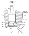
- FIG.11 shows a further embodiment of an in-cylinder fuel injection device in accordance with the present invention in which a part of intake air is blown from the side surface of the in-cylinder fuel injection device 76.
- a part of intake-air is introduced into an air-intake chamber 100 formed by the in-cylinder fuel injection device 76, an inserting hole 97 of the cylinder head 89, and sealing members 98, 99. That is, the intake-air is introduced through an air-intake passage 101 and an intake -air control valve unit 102 provided in the cylinder head 89.
- the intake-air blows off the fuel droplets attached onto the surrounding of the in-cylinder fuel injection device 76 to flow into the combustion chamber together with the fuel droplets.
- inner pressure of the combustion chamber is started to increase.
- the air-intake control valve unit 102 is operated to prevent the mixed gas from flowing backward into the cylinder head 89.
- combustion heat is immediately transmitted to the in-cylinder fuel injection device 76 and consequently temperature of the top end portion of the in-cylinder fuel injection device is increased. Thereby, the temperature of the top end portion of the in-cylinder fuel injection device is easily heated up to the self-cleaning temperature of deposits described above to suppress deposits and soot from attaching and accumulating.
Landscapes
- Engineering & Computer Science (AREA)
- Chemical & Material Sciences (AREA)
- Combustion & Propulsion (AREA)
- Mechanical Engineering (AREA)
- General Engineering & Computer Science (AREA)
- Physics & Mathematics (AREA)
- Electromagnetism (AREA)
- Fuel-Injection Apparatus (AREA)
Applications Claiming Priority (3)
| Application Number | Priority Date | Filing Date | Title |
|---|---|---|---|
| JP2645396 | 1996-02-14 | ||
| JP26453/96 | 1996-02-14 | ||
| JP02645396A JP3478920B2 (ja) | 1996-02-14 | 1996-02-14 | 筒内燃料噴射装置およびそれを搭載した内燃機関 |
Publications (2)
| Publication Number | Publication Date |
|---|---|
| EP0790404A1 true EP0790404A1 (fr) | 1997-08-20 |
| EP0790404B1 EP0790404B1 (fr) | 2003-08-20 |
Family
ID=12193934
Family Applications (1)
| Application Number | Title | Priority Date | Filing Date |
|---|---|---|---|
| EP97102258A Expired - Lifetime EP0790404B1 (fr) | 1996-02-14 | 1997-02-12 | Dispositif d'injection directe de combustible et moteur à combustion interne équipé du dit dispositif |
Country Status (5)
| Country | Link |
|---|---|
| US (1) | US5915352A (fr) |
| EP (1) | EP0790404B1 (fr) |
| JP (1) | JP3478920B2 (fr) |
| KR (1) | KR100233754B1 (fr) |
| DE (1) | DE69724172T2 (fr) |
Cited By (6)
| Publication number | Priority date | Publication date | Assignee | Title |
|---|---|---|---|---|
| FR2772432A1 (fr) * | 1997-12-12 | 1999-06-18 | Magneti Marelli France | Injecteur d'essence a revetement ceramique anti-calamine, pour injection directe |
| WO2000042303A1 (fr) * | 1999-01-13 | 2000-07-20 | Siemens Automotive Corporation | Injecteur de carburant a commande pneumatique avec element de tourbillonnement du carburant |
| EP0918155A3 (fr) * | 1997-11-26 | 2002-08-21 | Hitachi, Ltd. | Soupape d'injection de combustible |
| DE10142299A1 (de) * | 2001-08-29 | 2003-04-17 | Bosch Gmbh Robert | Brennstoffeinspritzsystem |
| US6935578B1 (en) | 1998-11-25 | 2005-08-30 | Hitachi, Ltd. | Fuel injection valve |
| KR100775880B1 (ko) * | 2000-12-21 | 2007-11-13 | 아이에프피 | 열전달 수단을 포함하는 내연 엔진용 액상 가스 연료 인젝터 장치 |
Families Citing this family (26)
| Publication number | Priority date | Publication date | Assignee | Title |
|---|---|---|---|---|
| DE19937961A1 (de) * | 1999-08-11 | 2001-02-15 | Bosch Gmbh Robert | Brennstoffeinspritzventil und Verfahren zur Herstellung von Austrittsöffnungen an Ventilen |
| AUPQ671500A0 (en) * | 2000-04-05 | 2000-05-04 | Orbital Engine Company (Australia) Proprietary Limited | Fuel injector nozzles |
| DE10049518B4 (de) * | 2000-10-06 | 2005-11-24 | Robert Bosch Gmbh | Brennstoffeinspritzventil |
| DE10130685A1 (de) * | 2001-06-26 | 2003-01-02 | Bosch Gmbh Robert | Brennstoffeinspritzventil |
| DE10148597A1 (de) * | 2001-10-02 | 2003-08-21 | Bosch Gmbh Robert | Brennstoffeinspritzventil |
| JP4147405B2 (ja) * | 2003-09-25 | 2008-09-10 | 株式会社デンソー | 燃料噴射弁 |
| CA2442601C (fr) * | 2003-09-26 | 2005-05-24 | Westport Research Inc. | Systeme d'injection de carburant et methode de fonctionnement pour moteur a carburant gazeux avec preinjection pour allumage par carburant liquide |
| JP4034263B2 (ja) * | 2003-12-25 | 2008-01-16 | 三菱電機株式会社 | 燃料噴射弁及びスワラー製造方法 |
| US7438241B2 (en) * | 2004-11-05 | 2008-10-21 | Visteon Global Technologies, Inc. | Low pressure fuel injector nozzle |
| US7137577B2 (en) * | 2004-11-05 | 2006-11-21 | Visteon Global Technologies, Inc. | Low pressure fuel injector nozzle |
| US7124963B2 (en) * | 2004-11-05 | 2006-10-24 | Visteon Global Technologies, Inc. | Low pressure fuel injector nozzle |
| US7198207B2 (en) * | 2004-11-05 | 2007-04-03 | Visteon Global Technologies, Inc. | Low pressure fuel injector nozzle |
| US7051957B1 (en) * | 2004-11-05 | 2006-05-30 | Visteon Global Technologies, Inc. | Low pressure fuel injector nozzle |
| US7104475B2 (en) * | 2004-11-05 | 2006-09-12 | Visteon Global Technologies, Inc. | Low pressure fuel injector nozzle |
| US7185831B2 (en) * | 2004-11-05 | 2007-03-06 | Ford Motor Company | Low pressure fuel injector nozzle |
| US7168637B2 (en) * | 2004-11-05 | 2007-01-30 | Visteon Global Technologies, Inc. | Low pressure fuel injector nozzle |
| DE102010028863A1 (de) * | 2010-05-11 | 2011-11-17 | Robert Bosch Gmbh | Vorrichtung zur Reduktion von Schadstoffen im Abgasstrom eines Verbrennungsmotors |
| US8690080B2 (en) * | 2011-09-21 | 2014-04-08 | Delavan Inc | Compact high flow pressure atomizers |
| KR20150032914A (ko) * | 2012-08-01 | 2015-03-30 | 쓰리엠 이노베이티브 프로퍼티즈 컴파니 | 적어도 하나의 다중 입구 포트 및/또는 다중 출구 포트를 가진 연료 분사기 노즐 |
| DE102012214522B3 (de) * | 2012-08-15 | 2014-03-27 | Ford Global Technologies, Llc | Einspritzventil |
| US9790906B2 (en) | 2014-08-15 | 2017-10-17 | Continental Automotive Systems, Inc. | High pressure gasoline injector seat to reduce particle emissions |
| AT519022B1 (de) * | 2016-06-06 | 2018-03-15 | Forschungsgesellschaft Fuer Verbrennungskraftmaschinen Und Thermodynamik Mbh | Zweitakt-Verbrennungsmotor |
| CN106224148B (zh) * | 2016-08-02 | 2018-12-11 | 成都威特电喷有限责任公司 | 带有转接螺套的电控高压燃油喷射装置 |
| CN106050501B (zh) * | 2016-08-02 | 2018-09-11 | 成都威特电喷有限责任公司 | 高可靠性电控高压燃油喷射装置 |
| JP6520897B2 (ja) | 2016-11-16 | 2019-05-29 | トヨタ自動車株式会社 | 内燃機関 |
| US11428188B1 (en) * | 2021-07-01 | 2022-08-30 | Caterpillar Inc. | Unclogging of ducts for fuel injection |
Citations (12)
| Publication number | Priority date | Publication date | Assignee | Title |
|---|---|---|---|---|
| BE531495A (fr) * | ||||
| GB251121A (en) * | 1925-05-28 | 1926-04-29 | Maschf Augsburg Nuernberg Ag | Improvements in or relating to internal combustion engines of the solid fuel injection type |
| CH290996A (de) * | 1951-04-24 | 1953-05-31 | Saurer Ag Adolph | Einspritzdüse für Dieselmotoren. |
| DE1526709A1 (de) * | 1966-01-19 | 1970-03-05 | Maschf Augsburg Nuernberg Ag | Fluessigkeitsgekuehlte Einspritzduese fuer Brennkraftmaschinen |
| GB2069045A (en) * | 1980-02-05 | 1981-08-19 | Kloeckner Humboldt Deutz Ag | Heat-insulated fuel injection nozzle |
| JPS5872671A (ja) * | 1981-10-23 | 1983-04-30 | Hitachi Zosen Corp | 燃料噴射弁 |
| EP0151793A2 (fr) * | 1984-02-10 | 1985-08-21 | Robert Bosch Gmbh | Buse d'injection de combustible pour moteurs à combustion interne |
| DE3623221A1 (de) * | 1986-07-10 | 1988-02-04 | Daimler Benz Ag | Kraftstoffeinspritzduese, insbesondere lochduese fuer direkteinspritzende brennkraftmaschinen |
| WO1988003226A1 (fr) * | 1986-10-30 | 1988-05-05 | Allied Corporation | Injecteur muni d'une chambre de tourbillonnement |
| DE3735526A1 (de) * | 1986-10-24 | 1988-05-05 | Nippon Denso Co | Elektromagnetisches kraftstoff-einspritzventil fuer eine brennkraftmaschine |
| US5307997A (en) * | 1993-03-12 | 1994-05-03 | Siemens Automotive L.P. | Fuel injector swirl passages |
| US5360166A (en) * | 1991-03-20 | 1994-11-01 | Hitachi, Ltd. | Fuel injection valve |
Family Cites Families (8)
| Publication number | Priority date | Publication date | Assignee | Title |
|---|---|---|---|---|
| DE290996C (fr) * | ||||
| US4245589A (en) * | 1978-07-18 | 1981-01-20 | Ryan Joseph C | Exothermic injector adapter |
| US4981266A (en) * | 1981-05-30 | 1991-01-01 | Robert Bosch Gmbh | Injection valve |
| DE3943005A1 (de) * | 1988-12-28 | 1990-07-05 | Hitachi Ltd | Elektromagnetische einspritzventilvorrichtung |
| US5285969A (en) * | 1989-11-25 | 1994-02-15 | Robert Bosch Gmbh | Electromagnetically operated fuel injection valve |
| US4971254A (en) * | 1989-11-28 | 1990-11-20 | Siemens-Bendix Automotive Electronics L.P. | Thin orifice swirl injector nozzle |
| US5207384A (en) * | 1991-09-18 | 1993-05-04 | Siemens Automotive L.P. | Swirl generator for an injector |
| US5570841A (en) * | 1994-10-07 | 1996-11-05 | Siemens Automotive Corporation | Multiple disk swirl atomizer for fuel injector |
-
1996
- 1996-02-14 JP JP02645396A patent/JP3478920B2/ja not_active Expired - Fee Related
-
1997
- 1997-02-07 US US08/796,558 patent/US5915352A/en not_active Expired - Lifetime
- 1997-02-12 DE DE69724172T patent/DE69724172T2/de not_active Expired - Fee Related
- 1997-02-12 EP EP97102258A patent/EP0790404B1/fr not_active Expired - Lifetime
- 1997-02-13 KR KR1019970004202A patent/KR100233754B1/ko not_active Expired - Fee Related
Patent Citations (12)
| Publication number | Priority date | Publication date | Assignee | Title |
|---|---|---|---|---|
| BE531495A (fr) * | ||||
| GB251121A (en) * | 1925-05-28 | 1926-04-29 | Maschf Augsburg Nuernberg Ag | Improvements in or relating to internal combustion engines of the solid fuel injection type |
| CH290996A (de) * | 1951-04-24 | 1953-05-31 | Saurer Ag Adolph | Einspritzdüse für Dieselmotoren. |
| DE1526709A1 (de) * | 1966-01-19 | 1970-03-05 | Maschf Augsburg Nuernberg Ag | Fluessigkeitsgekuehlte Einspritzduese fuer Brennkraftmaschinen |
| GB2069045A (en) * | 1980-02-05 | 1981-08-19 | Kloeckner Humboldt Deutz Ag | Heat-insulated fuel injection nozzle |
| JPS5872671A (ja) * | 1981-10-23 | 1983-04-30 | Hitachi Zosen Corp | 燃料噴射弁 |
| EP0151793A2 (fr) * | 1984-02-10 | 1985-08-21 | Robert Bosch Gmbh | Buse d'injection de combustible pour moteurs à combustion interne |
| DE3623221A1 (de) * | 1986-07-10 | 1988-02-04 | Daimler Benz Ag | Kraftstoffeinspritzduese, insbesondere lochduese fuer direkteinspritzende brennkraftmaschinen |
| DE3735526A1 (de) * | 1986-10-24 | 1988-05-05 | Nippon Denso Co | Elektromagnetisches kraftstoff-einspritzventil fuer eine brennkraftmaschine |
| WO1988003226A1 (fr) * | 1986-10-30 | 1988-05-05 | Allied Corporation | Injecteur muni d'une chambre de tourbillonnement |
| US5360166A (en) * | 1991-03-20 | 1994-11-01 | Hitachi, Ltd. | Fuel injection valve |
| US5307997A (en) * | 1993-03-12 | 1994-05-03 | Siemens Automotive L.P. | Fuel injector swirl passages |
Non-Patent Citations (1)
| Title |
|---|
| PATENT ABSTRACTS OF JAPAN vol. 007, no. 165 (M - 230) 20 July 1983 (1983-07-20) * |
Cited By (9)
| Publication number | Priority date | Publication date | Assignee | Title |
|---|---|---|---|---|
| EP0918155A3 (fr) * | 1997-11-26 | 2002-08-21 | Hitachi, Ltd. | Soupape d'injection de combustible |
| FR2772432A1 (fr) * | 1997-12-12 | 1999-06-18 | Magneti Marelli France | Injecteur d'essence a revetement ceramique anti-calamine, pour injection directe |
| WO1999031382A1 (fr) * | 1997-12-12 | 1999-06-24 | Magneti Marelli France | Injecteur d'essence a revetement ceramique anti-calamine, pour injection directe |
| US6267307B1 (en) | 1997-12-12 | 2001-07-31 | Magneti Marelli France | Fuel injector with anti-scale ceramic coating for direct injection |
| US6935578B1 (en) | 1998-11-25 | 2005-08-30 | Hitachi, Ltd. | Fuel injection valve |
| WO2000042303A1 (fr) * | 1999-01-13 | 2000-07-20 | Siemens Automotive Corporation | Injecteur de carburant a commande pneumatique avec element de tourbillonnement du carburant |
| US6205983B1 (en) | 1999-01-13 | 2001-03-27 | Siemens Automotive Corporation | Air assist fuel injector with fuel swirl feature |
| KR100775880B1 (ko) * | 2000-12-21 | 2007-11-13 | 아이에프피 | 열전달 수단을 포함하는 내연 엔진용 액상 가스 연료 인젝터 장치 |
| DE10142299A1 (de) * | 2001-08-29 | 2003-04-17 | Bosch Gmbh Robert | Brennstoffeinspritzsystem |
Also Published As
| Publication number | Publication date |
|---|---|
| DE69724172D1 (de) | 2003-09-25 |
| DE69724172T2 (de) | 2004-06-03 |
| EP0790404B1 (fr) | 2003-08-20 |
| KR100233754B1 (ko) | 1999-12-01 |
| JP3478920B2 (ja) | 2003-12-15 |
| US5915352A (en) | 1999-06-29 |
| KR970062314A (ko) | 1997-09-12 |
| JPH09217669A (ja) | 1997-08-19 |
Similar Documents
| Publication | Publication Date | Title |
|---|---|---|
| EP0790404A1 (fr) | Dispositif d'injection directe de combustible et moteur à combustion interne équipé du dit dispositif | |
| US4899699A (en) | Low pressure injection system for injecting fuel directly into cylinder of gasoline engine | |
| JP2711365B2 (ja) | 気化インジェクタ | |
| US7059307B2 (en) | Fuel injector for an internal combustion engine | |
| JP5204488B2 (ja) | 高周波蒸発燃料噴射装置 | |
| CN100451325C (zh) | 用于内燃机的带配量阀的毛细管燃料喷射器 | |
| KR20010089323A (ko) | 엔진용 연료-공기 혼합기 | |
| JP4323325B2 (ja) | 内燃機関のための燃料インジェクタ | |
| EP1756413A2 (fr) | Systemes a vapeur de carburant pour moteurs a combustion interne | |
| US7357124B2 (en) | Multiple capillary fuel injector for an internal combustion engine | |
| JP2002115628A (ja) | 燃料噴射弁および内燃機関 | |
| CN101208508A (zh) | 用于内燃机的燃料蒸气系统 | |
| JP3044876B2 (ja) | 内燃機関用電子制御燃料噴射装置 | |
| JP2001317434A (ja) | 内燃機関の燃料噴射方法および燃料噴射装置 | |
| JPH11336643A (ja) | 筒内噴射用電磁式燃料噴射弁 | |
| JP2004537004A (ja) | 直接燃料噴射式熱機関のための混合気の形成および燃焼方法 | |
| JPH0225031B2 (fr) | ||
| JP2005518498A (ja) | 燃料噴射弁 | |
| JP2850035B2 (ja) | 燃料噴射弁 | |
| JPH1113587A (ja) | 筒内燃料噴射装置 | |
| JP2851170B2 (ja) | 内燃機関の燃料供給装置 | |
| JP3040008B2 (ja) | 電磁式燃料噴射弁 | |
| WO2007043820A1 (fr) | Structure de buse d'injection d'un injecteur | |
| JP2000314355A (ja) | 筒内燃料噴射装置 | |
| JPH06336965A (ja) | 燃料供給装置 |
Legal Events
| Date | Code | Title | Description |
|---|---|---|---|
| PUAI | Public reference made under article 153(3) epc to a published international application that has entered the european phase |
Free format text: ORIGINAL CODE: 0009012 |
|
| AK | Designated contracting states |
Kind code of ref document: A1 Designated state(s): DE GB IT |
|
| 17P | Request for examination filed |
Effective date: 19970626 |
|
| 17Q | First examination report despatched |
Effective date: 19990916 |
|
| GRAH | Despatch of communication of intention to grant a patent |
Free format text: ORIGINAL CODE: EPIDOS IGRA |
|
| GRAH | Despatch of communication of intention to grant a patent |
Free format text: ORIGINAL CODE: EPIDOS IGRA |
|
| GRAA | (expected) grant |
Free format text: ORIGINAL CODE: 0009210 |
|
| AK | Designated contracting states |
Designated state(s): DE GB IT |
|
| REG | Reference to a national code |
Ref country code: GB Ref legal event code: FG4D |
|
| REF | Corresponds to: |
Ref document number: 69724172 Country of ref document: DE Date of ref document: 20030925 Kind code of ref document: P |
|
| PLBE | No opposition filed within time limit |
Free format text: ORIGINAL CODE: 0009261 |
|
| STAA | Information on the status of an ep patent application or granted ep patent |
Free format text: STATUS: NO OPPOSITION FILED WITHIN TIME LIMIT |
|
| 26N | No opposition filed |
Effective date: 20040524 |
|
| PGFP | Annual fee paid to national office [announced via postgrant information from national office to epo] |
Ref country code: GB Payment date: 20050125 Year of fee payment: 9 |
|
| PGFP | Annual fee paid to national office [announced via postgrant information from national office to epo] |
Ref country code: DE Payment date: 20050304 Year of fee payment: 9 |
|
| PG25 | Lapsed in a contracting state [announced via postgrant information from national office to epo] |
Ref country code: GB Free format text: LAPSE BECAUSE OF NON-PAYMENT OF DUE FEES Effective date: 20060212 |
|
| PGFP | Annual fee paid to national office [announced via postgrant information from national office to epo] |
Ref country code: IT Payment date: 20060228 Year of fee payment: 10 |
|
| PG25 | Lapsed in a contracting state [announced via postgrant information from national office to epo] |
Ref country code: DE Free format text: LAPSE BECAUSE OF NON-PAYMENT OF DUE FEES Effective date: 20060901 |
|
| GBPC | Gb: european patent ceased through non-payment of renewal fee |
Effective date: 20060212 |
|
| PG25 | Lapsed in a contracting state [announced via postgrant information from national office to epo] |
Ref country code: IT Free format text: LAPSE BECAUSE OF NON-PAYMENT OF DUE FEES Effective date: 20070212 |