EP0790412A2 - Hydraulische Wahlschaltung - Google Patents
Hydraulische Wahlschaltung Download PDFInfo
- Publication number
- EP0790412A2 EP0790412A2 EP97400150A EP97400150A EP0790412A2 EP 0790412 A2 EP0790412 A2 EP 0790412A2 EP 97400150 A EP97400150 A EP 97400150A EP 97400150 A EP97400150 A EP 97400150A EP 0790412 A2 EP0790412 A2 EP 0790412A2
- Authority
- EP
- European Patent Office
- Prior art keywords
- chamber
- conduit
- chambers
- slide
- hydraulic circuit
- Prior art date
- Legal status (The legal status is an assumption and is not a legal conclusion. Google has not performed a legal analysis and makes no representation as to the accuracy of the status listed.)
- Granted
Links
Images



Classifications
-
- F—MECHANICAL ENGINEERING; LIGHTING; HEATING; WEAPONS; BLASTING
- F16—ENGINEERING ELEMENTS AND UNITS; GENERAL MEASURES FOR PRODUCING AND MAINTAINING EFFECTIVE FUNCTIONING OF MACHINES OR INSTALLATIONS; THERMAL INSULATION IN GENERAL
- F16K—VALVES; TAPS; COCKS; ACTUATING-FLOATS; DEVICES FOR VENTING OR AERATING
- F16K37/00—Special means in or on valves or other cut-off apparatus for indicating or recording operation thereof, or for enabling an alarm to be given
-
- F—MECHANICAL ENGINEERING; LIGHTING; HEATING; WEAPONS; BLASTING
- F15—FLUID-PRESSURE ACTUATORS; HYDRAULICS OR PNEUMATICS IN GENERAL
- F15C—FLUID-CIRCUIT ELEMENTS PREDOMINANTLY USED FOR COMPUTING OR CONTROL PURPOSES
- F15C1/00—Circuit elements having no moving parts
- F15C1/02—Details, e.g. special constructional devices for circuits with fluid elements, such as resistances, capacitive circuit elements; devices preventing reaction coupling in composite elements ; Switch boards; Program devices
- F15C1/04—Means for controlling fluid streams to fluid devices, e.g. by electric signals or other signals, no mixing taking place between the signal and the flow to be controlled
-
- F—MECHANICAL ENGINEERING; LIGHTING; HEATING; WEAPONS; BLASTING
- F15—FLUID-PRESSURE ACTUATORS; HYDRAULICS OR PNEUMATICS IN GENERAL
- F15B—SYSTEMS ACTING BY MEANS OF FLUIDS IN GENERAL; FLUID-PRESSURE ACTUATORS, e.g. SERVOMOTORS; DETAILS OF FLUID-PRESSURE SYSTEMS, NOT OTHERWISE PROVIDED FOR
- F15B13/00—Details of servomotor systems ; Valves for servomotor systems
- F15B13/02—Fluid distribution or supply devices characterised by their adaptation to the control of servomotors
-
- F—MECHANICAL ENGINEERING; LIGHTING; HEATING; WEAPONS; BLASTING
- F15—FLUID-PRESSURE ACTUATORS; HYDRAULICS OR PNEUMATICS IN GENERAL
- F15B—SYSTEMS ACTING BY MEANS OF FLUIDS IN GENERAL; FLUID-PRESSURE ACTUATORS, e.g. SERVOMOTORS; DETAILS OF FLUID-PRESSURE SYSTEMS, NOT OTHERWISE PROVIDED FOR
- F15B13/00—Details of servomotor systems ; Valves for servomotor systems
- F15B13/02—Fluid distribution or supply devices characterised by their adaptation to the control of servomotors
- F15B13/04—Fluid distribution or supply devices characterised by their adaptation to the control of servomotors for use with a single servomotor
- F15B13/0401—Valve members; Fluid interconnections therefor
- F15B13/0405—Valve members; Fluid interconnections therefor for seat valves, i.e. poppet valves
-
- F—MECHANICAL ENGINEERING; LIGHTING; HEATING; WEAPONS; BLASTING
- F15—FLUID-PRESSURE ACTUATORS; HYDRAULICS OR PNEUMATICS IN GENERAL
- F15B—SYSTEMS ACTING BY MEANS OF FLUIDS IN GENERAL; FLUID-PRESSURE ACTUATORS, e.g. SERVOMOTORS; DETAILS OF FLUID-PRESSURE SYSTEMS, NOT OTHERWISE PROVIDED FOR
- F15B15/00—Fluid-actuated devices for displacing a member from one position to another; Gearing associated therewith
- F15B15/20—Other details, e.g. assembly with regulating devices
- F15B15/28—Means for indicating the position, e.g. end of stroke
-
- F—MECHANICAL ENGINEERING; LIGHTING; HEATING; WEAPONS; BLASTING
- F16—ENGINEERING ELEMENTS AND UNITS; GENERAL MEASURES FOR PRODUCING AND MAINTAINING EFFECTIVE FUNCTIONING OF MACHINES OR INSTALLATIONS; THERMAL INSULATION IN GENERAL
- F16K—VALVES; TAPS; COCKS; ACTUATING-FLOATS; DEVICES FOR VENTING OR AERATING
- F16K11/00—Multiple-way valves, e.g. mixing valves; Pipe fittings incorporating such valves
- F16K11/02—Multiple-way valves, e.g. mixing valves; Pipe fittings incorporating such valves with all movable sealing faces moving as one unit
- F16K11/06—Multiple-way valves, e.g. mixing valves; Pipe fittings incorporating such valves with all movable sealing faces moving as one unit comprising only sliding valves, i.e. sliding closure elements
-
- F—MECHANICAL ENGINEERING; LIGHTING; HEATING; WEAPONS; BLASTING
- F16—ENGINEERING ELEMENTS AND UNITS; GENERAL MEASURES FOR PRODUCING AND MAINTAINING EFFECTIVE FUNCTIONING OF MACHINES OR INSTALLATIONS; THERMAL INSULATION IN GENERAL
- F16K—VALVES; TAPS; COCKS; ACTUATING-FLOATS; DEVICES FOR VENTING OR AERATING
- F16K27/00—Construction of housing; Use of materials therefor
- F16K27/04—Construction of housing; Use of materials therefor of sliding valves
Definitions
- the invention relates to a hydraulic circuit selector, connected on the one hand to a first hydraulic circuit of high pressure energy source and of low pressure network in the opposite direction and on the other hand to a second hydraulic circuit of a reversible differential pressure consumer, with a volumetric meter of a hydraulic fluid for consumer control.
- the motorization of taps uses actuators, electric, pneumatic, hydraulic or mechanical.
- Position control for its part, is generally ensured by a position detection of the shutter shaft using generally electric position sensors, eg a limit switch or a potentiometer.
- the flow meter is mounted in a branch of the hydraulic circuit connecting the hydraulic cylinder to a hydraulic circuit selector in reversible direction.
- This selector achieves at least three different states of the hydraulic circuit. First, it allows the flow of high pressure fluid in a working chamber of the jack to push the piston. This movement of the piston acts on the second working chamber opposite the piston and the fluid included in this chamber is moved to the tank at low pressure. Secondly, after the end of the movement, the selector puts the hydraulic circuit at rest at low pressure. Thirdly, the reversible hydraulic circuit makes it possible to load the second working chamber of the cylinder with a high pressure to cause a reverse movement of the piston.
- any variation in volume between the meter and the actuator can cause the sensor to drift, without the piston and the shutter moving.
- This variation is due in particular to temperature variations, which is common on a ship deck between day and night for example, possible internal leaks from the actuator or fittings of the installation and variations in the pressure of the hydraulic power unit if it keeps the meter line under pressure while the tap is off.
- the third hydraulic circuit is placed in communication with the low pressure side during the operation of the consumer. This makes it possible to carry out this volume measurement without being disturbed by the variation in the driving pressure of the power station.
- the third circuit is isolated when the consumer is stopped.
- the meter is isolated from the conduits connecting the hydraulic power unit to the consumer in the phases where the consumer is stopped so that any change in volume due to internal leaks or temperature variations has no influence on the counter indicator stopped.
- the selector first puts the third hydraulic circuit in communication with the low pressure side of the second circuit before opening the high pressure side of the consumer's second hydraulic circuit.
- Hydraulic selectors of this kind have drawbacks, however.
- the various functions performed by the hydraulic diagram described in document WO 92/19871 are obtained by means of an assembly of components, in particular commercial components, so that the device according to the prior art is bulky and does not appear in the form of a robust selector block, compact and integrating the different functions.
- the present invention thus relates to a hydraulic selector block, which, connected on the one hand to a first hydraulic circuit of high-pressure energy source, and on the other hand to a second hydraulic circuit of a consumer of directional differential pressure reverse, by a flow sensor or a volumetric meter of a hydraulic fluid for consumer control, integrates, according to a robust and space-saving assembly, the functions which consist in placing the flow sensor in a third hydraulic circuit at substantially constant pressure , the selector always putting the same consumer pressure side in communication with the third hydraulic circuit of the flow sensor or of the volumetric meter, to put the third hydraulic circuit in communication with the low pressure side during the operation of the consumer, to isolate the third hydraulic circuit when the consumer is stopped, and to put first the third hydraulic circuit in communication with the low pressure side of the second hydraulic circuit before opening the high pressure side of the second hydraulic circuit of the consumer.
- the pushing means comprise, in each of the first and seventh chambers, a jack provided with a jack opening and a stop which are part of the pushing means and a valve, the opening of cylinder for guiding the valve, this last, under the effect of the pressure of the fluid in the first chamber, respectively seventh chamber, closing the second conduit, respectively the eighth conduit, and the jack stop, pushing the valve against the slide so as to move the slide in the direction from the first to the seventh chamber, respectively from the seventh to the first chamber, up to a third stop, respectively fourth stop.
- the selector block is symmetrical as in a mirror with respect to a median plane of the fourth chamber, the second and eighth conduits are T-shaped and the slide is in two pieces
- the first hydraulic circuit 1 comprises a high pressure side 5 of an energy source, for example a hydraulic power station, and a low pressure side 6 of the network, for example back to the tank of the hydraulic power plant.
- the arrow P indicates the direction of flow of a fluid, eg oil, under high pressure to a hydraulic distributor 7 provided for reversing the direction of the differential pressure in the first hydraulic circuit 1, the arrow T designates the return to the tank.
- a fluid eg oil
- a position called rest is recognized where the distributor 7 cuts the high pressure side 5 of the first circuit 1 and puts the selector 4 in communication by conduits 11,12 with the low pressure side 6 of the return to the tank. In this case, no operating energy is supplied by the first circuit 1 to the selector 4.
- the second hydraulic circuit 2 connects the selector 4 to an energy consumer 13 in the form of an actuator cylinder by conduits 14,15.
- the cylinder 13 there is a rack piston 16 cooperating with a toothed shaft 17 of a stop device, eg a tap, not shown.
- the cylinder 13 is a double-acting cylinder with working chambers 18,19 on each side of the piston 16.
- the conduits 14,15 are in communication with the distributor 7 through the selector 4 and therefore subject to low pressure. No driving force is exerted on the piston by the hydraulic circuits 1,2,3.
- the conduit 15 subjects the working chamber 19 to a high pressure while the pressure in the working chamber 18 remains low.
- the pressure difference in the working chambers 18,19 applies a motive force to the piston 16 which moves by driving the shaft 17 in rotation. Due to the rotation of the shaft the stop device changes its "open” state “in” closed “state. The movement of the piston 16 displaces the fluid at low pressure in the working chamber 18 towards the selector 4 through the conduit 14 and the fluid leaves the selector 4 through the opening 20 towards the tank, indicated by the arrow T. In the state 10 of the distributor 7 the movement of the piston 16 is reversed.
- the third hydraulic circuit 3 connects a flow sensor or a volumetric meter 21 to the selector 4 by conduits 22,23.
- the circuit 3 is blocked, there is no flow in the conduits 22, 23 and the counter 21 is isolated from the first and second hydraulic circuits 1, 2. Thanks to the isolation of the meter, it cannot drift.
- the flow coming from the low-pressure working chamber first passes through the third hydraulic circuit 3 and through the volumetric counter 21 before leaving the selector 4 through the opening 20 towards the tank. Thus, it is always the low pressure fluid which is taken into account to measure the volume moved and to indicate or calculate the state of the consumer 13.
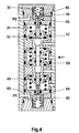
- the selector 4 is symmetrical to an axis of symmetry 38, its components being arranged in symmetry with respect to this axis 38.
- the channel 31, 37 is connected to the conduit 11, 12 of the first hydraulic circuit 1 and opens into the chamber 24, 30.
- a partially hollow cylinder 39.40 to receive a spring 41.42. Openings 43,44 facilitate the passage of the fluid inside the jack 39,40.
- the spring 41.42 presses the jack 39.40 against the body of the selector 4.
- the jack 39.40 receives in a central opening a movable part functioning as a valve 45.46 to open and close a passage 47.48 in a slide 49.50 in the form of a rod.
- a stop 62,63 is provided on the jack.
- the valve 46 is pressed against this stop 63 and finally causes the movement of the jack 40 against the force of the spring 42.
- the passage 47, 48 ends in the chamber 25, 29.
- the chamber 25, 29 is in communication with the conduit 14, 15 of the second hydraulic circuit via the channel 32, 36.
- a shutter 51.52 pressed against the selector body by a spring 53.54 and provided with a seal 55.56 to ensure a seal between the chamber 25.29 and the chamber 26.28.
- the shutter 51.52 is crossed in a sealed manner by the slide 49.50.
- the chamber 26, 28 is in communication with the conduit 22, 23 of the third hydraulic circuit 3 through the channel 33, 35.
- the slide 49.50 has an increased section portion 57.58 capable of functioning as a stop for the valves 51.52, on the one hand, and valves 59.60 in the chamber 27, on the other hand, during phases of different operations.
- valves 59.60 are placed back to back and a spacer spring 61 is placed between the valves 59.60. It is in this chamber 27 where the slides 49, 50 press against each other that the axis of symmetry 38 is located.
- All the parts of the selector are dimensioned in such a way that, in the rest state shown, the conduits 14,15 can be discharged towards the tank (T) through the selector 4 by the conduits 11,12.
- the fluid enters the selector 4 through the channel 32,36, crosses the chamber 25,29 to arrive at the passage 47,48 of the slide 49,50.
- the fluid leaves the passage 47, 48 in the chamber 24.30 after having passed the valves 45 and 46 allowing the passage of the fluid.
- the fluid leaves the chamber 24.30 in communication with the conduits 11.12 via the channel 31.37 to leave the selector 4.
- the third hydraulic circuit 3 of the meter As for the third hydraulic circuit 3 of the meter, it is blocked by the sealed support of the valves 51, 52; 59.60. No fluid can leave the conduits 22,23. The counter 21 is isolated and therefore cannot drift.
- the pressure P coming from the distributor 7 arrives at the channel 31 and subjects the chamber 24 under pressure. This pressure pushes the valve 45 against the slide 49 and the valve 45 seals with the slide 49 and prevents the passage of the fluid towards the chamber 25 through the passage 47.
- the sliders move opening the valves 59 and 52 until the valve 46 abuts 63 on the jack 40 retained by the springs 42.
- the valves 52.59 are moved by the support of the parts 57, 58 of the slides 49.50.
- the working chamber 18 of the consumer jack 13 is in communication with the tank by the conduit 14, the channel 36, the chamber 29, the chamber 28, the channel 35, the conduit 22, the counter 21, the conduit 23, channel 33, chamber 26, chamber 27 and channel 34.
- the third hydraulic circuit is therefore connected. As the valve 46 closes the passage 48 of the slide 50, all of the fluid leaving the working chamber 18 must pass through the volumetric counter 21 of the third circuit 3.
- the slider 49.50 continues to move, accentuating the opening of the valves 59 and 52 and compressing the jack 40 which ensures a certain sealing pressure of the valve 46 preventing any passage of fluid from the chamber 29 towards the chamber 30 through the passage 48.
- the slide 49, 50 continues its movement, accentuating the opening of the valves 59 and 52, completely compressing the jack 40 which, coming into abutment, seals the valve 46.
- the valve 45 being in abutment 64 on the face of an end jacket 66 allows the fluid under high pressure to pass from chamber 24 to chamber 25 ensuring the operation of the actuator.
- the consumer returns from the chamber 29 to the chamber 28 and the channel 35, crosses the counter, exits through the channel 33 and flows through the chambers 26, 27 towards the tank (T).
- the slide 49.50 has seals to maintain a differential pressure in the different chambers.
- the selector 4 is composed of several segments sealed against a body.
- the operation is identical with the admission of the pressure P into the conduit 12 instead of the conduit 11 and a reverse movement of the valves and of the slide.
- the counter 21 In the rest position, the counter 21 is completely isolated from the conduits 11, 12; 14.15 going from the distributor 7 to the cylinder 13. Any variation in volume for any reason whatsoever, cannot be counted by the counter, nor modify the position of its indicator.
- the hydraulic selector according to the invention can be used for controlling and controlling the position of actuators of valves and the like, eg for a valve device comprising a shutter rotating by a quarter turn.
Landscapes
- Engineering & Computer Science (AREA)
- General Engineering & Computer Science (AREA)
- Mechanical Engineering (AREA)
- Physics & Mathematics (AREA)
- Fluid Mechanics (AREA)
- Theoretical Computer Science (AREA)
- Fluid-Pressure Circuits (AREA)
- Check Valves (AREA)
Applications Claiming Priority (2)
| Application Number | Priority Date | Filing Date | Title |
|---|---|---|---|
| FR9601520A FR2744498B1 (fr) | 1996-02-02 | 1996-02-02 | Selecteur de circuit hydraulique |
| FR9601520 | 1996-02-02 |
Publications (3)
| Publication Number | Publication Date |
|---|---|
| EP0790412A2 true EP0790412A2 (de) | 1997-08-20 |
| EP0790412A3 EP0790412A3 (de) | 1998-07-01 |
| EP0790412B1 EP0790412B1 (de) | 2000-09-27 |
Family
ID=9488963
Family Applications (1)
| Application Number | Title | Priority Date | Filing Date |
|---|---|---|---|
| EP97400150A Expired - Lifetime EP0790412B1 (de) | 1996-02-02 | 1997-01-23 | Hydraulische Wahlschaltung |
Country Status (8)
| Country | Link |
|---|---|
| EP (1) | EP0790412B1 (de) |
| JP (1) | JPH109425A (de) |
| KR (1) | KR970062359A (de) |
| DE (1) | DE69703168T2 (de) |
| DK (1) | DK0790412T3 (de) |
| ES (1) | ES2151708T3 (de) |
| FR (1) | FR2744498B1 (de) |
| NO (1) | NO308327B1 (de) |
Cited By (4)
| Publication number | Priority date | Publication date | Assignee | Title |
|---|---|---|---|---|
| EP0921322A3 (de) * | 1997-12-06 | 2003-05-21 | Robert Bosch Gmbh | Pneumatisches Steuerventil |
| DE102008001520A1 (de) * | 2008-04-30 | 2010-02-04 | Georg Schünemann GmbH | Sitzventil |
| WO2012135490A1 (en) * | 2011-04-01 | 2012-10-04 | General Equipment And Manufacturing Company, Inc., D/B/A Topworx, Inc. | Poppet valve assembly for controlling a pneumatic actuator |
| WO2017039766A1 (en) * | 2015-09-03 | 2017-03-09 | Ross Operating Valve Company | Three position closed center poppet valve |
Families Citing this family (3)
| Publication number | Priority date | Publication date | Assignee | Title |
|---|---|---|---|---|
| DE102007042757A1 (de) * | 2007-09-07 | 2009-03-26 | Pleiger Maschinenbau Gmbh & Co. Kg | Verfahren und Vorrichtung zur Stellungsanzeige von hydraulisch betätigten Armaturen |
| JP5700449B2 (ja) * | 2011-09-12 | 2015-04-15 | 株式会社Taiyo | 切り替え弁装置 |
| KR101959792B1 (ko) * | 2017-09-11 | 2019-03-19 | 함광식 | 라쳇을 이용한 밸브 구동기 |
Citations (1)
| Publication number | Priority date | Publication date | Assignee | Title |
|---|---|---|---|---|
| WO1992019871A1 (en) | 1991-04-29 | 1992-11-12 | Nordisk Marine Hydraulik Danmark A/S | A position indicator for a hydraulic type setting motor |
Family Cites Families (7)
| Publication number | Priority date | Publication date | Assignee | Title |
|---|---|---|---|---|
| DE1050243B (de) * | 1959-02-05 | |||
| DE1232425B (de) * | 1962-03-05 | 1967-01-12 | Nordiska Armaturfab Ab | Anordnung zum Anzeigen der Stellung eines druckmittelbetaetigten Ventils ueber einenVolumenmesser |
| DE1231518B (de) * | 1964-06-30 | 1966-12-29 | Klein Schanzlin & Becker Ag | Stellungsanzeiger fuer hydraulisch fernbetaetigte Ventile u. dgl. |
| CH431217A (fr) * | 1965-11-11 | 1967-02-28 | Lucifer Sa | Valve à clapet |
| DE1601752A1 (de) * | 1967-06-03 | 1970-03-19 | Rexroth Gmbh G L | Steuerung hydraulischer Schwenkantriebe |
| DE3322912A1 (de) * | 1983-06-25 | 1985-01-03 | Wabco Steuerungstechnik GmbH & Co, 3000 Hannover | Mehrwege-sitzventil |
| US5103866A (en) * | 1991-02-22 | 1992-04-14 | Foster Raymond K | Poppet valve and valve assemblies utilizing same |
-
1996
- 1996-02-02 FR FR9601520A patent/FR2744498B1/fr not_active Expired - Fee Related
-
1997
- 1997-01-23 EP EP97400150A patent/EP0790412B1/de not_active Expired - Lifetime
- 1997-01-23 DK DK97400150T patent/DK0790412T3/da active
- 1997-01-23 DE DE69703168T patent/DE69703168T2/de not_active Expired - Fee Related
- 1997-01-23 ES ES97400150T patent/ES2151708T3/es not_active Expired - Lifetime
- 1997-01-31 NO NO970436A patent/NO308327B1/no not_active IP Right Cessation
- 1997-01-31 JP JP9032718A patent/JPH109425A/ja active Pending
- 1997-02-03 KR KR1019970003239A patent/KR970062359A/ko not_active Abandoned
Patent Citations (1)
| Publication number | Priority date | Publication date | Assignee | Title |
|---|---|---|---|---|
| WO1992019871A1 (en) | 1991-04-29 | 1992-11-12 | Nordisk Marine Hydraulik Danmark A/S | A position indicator for a hydraulic type setting motor |
Cited By (10)
| Publication number | Priority date | Publication date | Assignee | Title |
|---|---|---|---|---|
| EP0921322A3 (de) * | 1997-12-06 | 2003-05-21 | Robert Bosch Gmbh | Pneumatisches Steuerventil |
| DE102008001520A1 (de) * | 2008-04-30 | 2010-02-04 | Georg Schünemann GmbH | Sitzventil |
| EP2113698A3 (de) * | 2008-04-30 | 2012-01-04 | Georg Schünemann GmbH | Sitzventil |
| WO2012135490A1 (en) * | 2011-04-01 | 2012-10-04 | General Equipment And Manufacturing Company, Inc., D/B/A Topworx, Inc. | Poppet valve assembly for controlling a pneumatic actuator |
| CN102734500A (zh) * | 2011-04-01 | 2012-10-17 | 通用设备和制造公司 | 用于控制气动致动器的提升阀组件 |
| JP2014512496A (ja) * | 2011-04-01 | 2014-05-22 | ジェネラル イクイップメント アンド マニュファクチャリング カンパニー, インコーポレイテッド, ディー/ビー/エー トップワークス, インコーポレイテッド | 空圧式アクチュエータを制御するためのポペット弁アセンブリ |
| US9279433B2 (en) | 2011-04-01 | 2016-03-08 | General Equipment And Manufacturing Company, Inc. | Poppet valve assembly for controlling a pneumatic actuator |
| CN102734500B (zh) * | 2011-04-01 | 2017-04-12 | 通用设备和制造公司 | 用于控制气动致动器的提升阀组件 |
| WO2017039766A1 (en) * | 2015-09-03 | 2017-03-09 | Ross Operating Valve Company | Three position closed center poppet valve |
| US10234045B2 (en) | 2015-09-03 | 2019-03-19 | Ross Operating Valve Company | Three position closed center poppet valve |
Also Published As
| Publication number | Publication date |
|---|---|
| DE69703168T2 (de) | 2001-01-25 |
| DK0790412T3 (da) | 2000-10-23 |
| NO970436L (no) | 1997-08-04 |
| KR970062359A (ko) | 1997-09-12 |
| EP0790412B1 (de) | 2000-09-27 |
| JPH109425A (ja) | 1998-01-13 |
| ES2151708T3 (es) | 2001-01-01 |
| NO308327B1 (no) | 2000-08-28 |
| FR2744498A1 (fr) | 1997-08-08 |
| EP0790412A3 (de) | 1998-07-01 |
| NO970436D0 (no) | 1997-01-31 |
| DE69703168D1 (de) | 2000-11-02 |
| FR2744498B1 (fr) | 1998-03-06 |
Similar Documents
| Publication | Publication Date | Title |
|---|---|---|
| US3007490A (en) | Rotary valve control | |
| EP0790412B1 (de) | Hydraulische Wahlschaltung | |
| FR2535818A1 (fr) | Valve, notamment a quatre voies, pour raccorder l'entree et la sortie d'une source de fluide sous pression a une chambre de pression contenant un piston | |
| FR2564558A1 (fr) | Robinet a boisseau tournant spherique | |
| EP0088017B1 (de) | Hydraulisches Wegeschieberventil | |
| EP0396479B1 (de) | Hahn mit Kugelküken | |
| EP0579519B1 (de) | Servogesteuertes Ventil | |
| FR2731071A1 (fr) | Indicateur de pression differentielle | |
| US4457210A (en) | Rotary actuator with energy conservation | |
| BE897518A (fr) | Soupape de securite pilotee | |
| FR2847644A1 (fr) | Soupape a commande par solenoide | |
| FR2695184A1 (fr) | Vanne du type à siège cylindrique, à siège conique ou à tiroir. | |
| FR2526116A1 (fr) | Robinet a clapet, a controle de fuite, notamment pour l'industrie alimentaire | |
| EP0524104B1 (de) | Hydaulikmotor mit hin- und hergehendem Differentialkolben | |
| EP0605425A1 (de) | Ein positionsanzeiger für einen hydraulischen stellmotor. | |
| EP0656497B1 (de) | Sicherheitseinrichtung für ein Drehventil | |
| RU2065091C1 (ru) | Многоканальный резервированный привод и распределитель для подачи рабочей среды | |
| EP0019534A1 (de) | Druckmittel-, insbesondere hydraulisch betätigte Steuerung eines Gangschalt-Stufengetriebes | |
| FR2486240A1 (fr) | Vanne pour prise d'echantillons | |
| EP0396433B1 (de) | Fluidsteuervorrichtung und ein diese umfassender Servolenkungskreis | |
| EP1565678B1 (de) | Schiebersteuerventil | |
| CH636412A5 (fr) | Bloc de commande pneumatique pour securite bi-manuelle. | |
| MC2446A1 (fr) | Dispositif de réglage pour corriger le recouvrement des éléments de distribution d'un distributeur asservi par un système d'actionnement différentiel | |
| FR2828546A1 (fr) | Vanne de commande, utilisation de celle-ci et chromatographe en phase gazeuse comportant une vanne de commande | |
| WO2002088579A1 (fr) | Vanne |
Legal Events
| Date | Code | Title | Description |
|---|---|---|---|
| PUAI | Public reference made under article 153(3) epc to a published international application that has entered the european phase |
Free format text: ORIGINAL CODE: 0009012 |
|
| AK | Designated contracting states |
Kind code of ref document: A2 Designated state(s): DE DK ES FR IT |
|
| 17P | Request for examination filed |
Effective date: 19970811 |
|
| PUAL | Search report despatched |
Free format text: ORIGINAL CODE: 0009013 |
|
| AK | Designated contracting states |
Kind code of ref document: A3 Designated state(s): DE DK ES FR IT |
|
| GRAG | Despatch of communication of intention to grant |
Free format text: ORIGINAL CODE: EPIDOS AGRA |
|
| GRAG | Despatch of communication of intention to grant |
Free format text: ORIGINAL CODE: EPIDOS AGRA |
|
| GRAH | Despatch of communication of intention to grant a patent |
Free format text: ORIGINAL CODE: EPIDOS IGRA |
|
| 17Q | First examination report despatched |
Effective date: 20000203 |
|
| ITF | It: translation for a ep patent filed | ||
| GRAH | Despatch of communication of intention to grant a patent |
Free format text: ORIGINAL CODE: EPIDOS IGRA |
|
| GRAA | (expected) grant |
Free format text: ORIGINAL CODE: 0009210 |
|
| AK | Designated contracting states |
Kind code of ref document: B1 Designated state(s): DE DK ES FR IT |
|
| REG | Reference to a national code |
Ref country code: DK Ref legal event code: T3 |
|
| REF | Corresponds to: |
Ref document number: 69703168 Country of ref document: DE Date of ref document: 20001102 |
|
| REG | Reference to a national code |
Ref country code: ES Ref legal event code: FG2A Ref document number: 2151708 Country of ref document: ES Kind code of ref document: T3 |
|
| PLBE | No opposition filed within time limit |
Free format text: ORIGINAL CODE: 0009261 |
|
| STAA | Information on the status of an ep patent application or granted ep patent |
Free format text: STATUS: NO OPPOSITION FILED WITHIN TIME LIMIT |
|
| 26N | No opposition filed | ||
| PGFP | Annual fee paid to national office [announced via postgrant information from national office to epo] |
Ref country code: ES Payment date: 20040112 Year of fee payment: 8 |
|
| PGFP | Annual fee paid to national office [announced via postgrant information from national office to epo] |
Ref country code: DE Payment date: 20040121 Year of fee payment: 8 |
|
| PGFP | Annual fee paid to national office [announced via postgrant information from national office to epo] |
Ref country code: FR Payment date: 20040123 Year of fee payment: 8 Ref country code: DK Payment date: 20040123 Year of fee payment: 8 |
|
| PG25 | Lapsed in a contracting state [announced via postgrant information from national office to epo] |
Ref country code: IT Free format text: LAPSE BECAUSE OF NON-PAYMENT OF DUE FEES;WARNING: LAPSES OF ITALIAN PATENTS WITH EFFECTIVE DATE BEFORE 2007 MAY HAVE OCCURRED AT ANY TIME BEFORE 2007. THE CORRECT EFFECTIVE DATE MAY BE DIFFERENT FROM THE ONE RECORDED. Effective date: 20050123 |
|
| PG25 | Lapsed in a contracting state [announced via postgrant information from national office to epo] |
Ref country code: ES Free format text: LAPSE BECAUSE OF NON-PAYMENT OF DUE FEES Effective date: 20050124 |
|
| PG25 | Lapsed in a contracting state [announced via postgrant information from national office to epo] |
Ref country code: DK Free format text: LAPSE BECAUSE OF NON-PAYMENT OF DUE FEES Effective date: 20050131 |
|
| PG25 | Lapsed in a contracting state [announced via postgrant information from national office to epo] |
Ref country code: DE Free format text: LAPSE BECAUSE OF NON-PAYMENT OF DUE FEES Effective date: 20050802 |
|
| REG | Reference to a national code |
Ref country code: DK Ref legal event code: EBP |
|
| PG25 | Lapsed in a contracting state [announced via postgrant information from national office to epo] |
Ref country code: FR Free format text: LAPSE BECAUSE OF NON-PAYMENT OF DUE FEES Effective date: 20050930 |
|
| REG | Reference to a national code |
Ref country code: FR Ref legal event code: ST |
|
| REG | Reference to a national code |
Ref country code: ES Ref legal event code: FD2A Effective date: 20050124 |