EP0790465A1 - Einrichtung zur Überwachung eines Heizgerätes - Google Patents
Einrichtung zur Überwachung eines Heizgerätes Download PDFInfo
- Publication number
- EP0790465A1 EP0790465A1 EP96121009A EP96121009A EP0790465A1 EP 0790465 A1 EP0790465 A1 EP 0790465A1 EP 96121009 A EP96121009 A EP 96121009A EP 96121009 A EP96121009 A EP 96121009A EP 0790465 A1 EP0790465 A1 EP 0790465A1
- Authority
- EP
- European Patent Office
- Prior art keywords
- exhaust gas
- combustion air
- flow restrictor
- flow
- measuring
- Prior art date
- Legal status (The legal status is an assumption and is not a legal conclusion. Google has not performed a legal analysis and makes no representation as to the accuracy of the status listed.)
- Granted
Links
- 238000012806 monitoring device Methods 0.000 title description 7
- 238000002485 combustion reaction Methods 0.000 claims abstract description 39
- 238000010438 heat treatment Methods 0.000 claims abstract 2
- 238000012544 monitoring process Methods 0.000 claims description 3
- 238000005259 measurement Methods 0.000 abstract description 5
- 239000007789 gas Substances 0.000 description 28
- 230000002950 deficient Effects 0.000 description 2
- 239000012528 membrane Substances 0.000 description 2
- 239000000567 combustion gas Substances 0.000 description 1
- 230000007423 decrease Effects 0.000 description 1
- 238000013461 design Methods 0.000 description 1
- 238000001514 detection method Methods 0.000 description 1
- 239000003344 environmental pollutant Substances 0.000 description 1
- 238000011156 evaluation Methods 0.000 description 1
- 239000002737 fuel gas Substances 0.000 description 1
- 238000011835 investigation Methods 0.000 description 1
- 231100000719 pollutant Toxicity 0.000 description 1
- 230000003068 static effect Effects 0.000 description 1
- 238000011144 upstream manufacturing Methods 0.000 description 1
Images

Classifications
-
- F—MECHANICAL ENGINEERING; LIGHTING; HEATING; WEAPONS; BLASTING
- F23—COMBUSTION APPARATUS; COMBUSTION PROCESSES
- F23N—REGULATING OR CONTROLLING COMBUSTION
- F23N5/00—Systems for controlling combustion
- F23N5/18—Systems for controlling combustion using detectors sensitive to rate of flow of air or fuel
- F23N5/188—Systems for controlling combustion using detectors sensitive to rate of flow of air or fuel using mechanical means
-
- F—MECHANICAL ENGINEERING; LIGHTING; HEATING; WEAPONS; BLASTING
- F23—COMBUSTION APPARATUS; COMBUSTION PROCESSES
- F23N—REGULATING OR CONTROLLING COMBUSTION
- F23N5/00—Systems for controlling combustion
- F23N5/24—Preventing development of abnormal or undesired conditions, i.e. safety arrangements
- F23N5/245—Preventing development of abnormal or undesired conditions, i.e. safety arrangements using electrical or electromechanical means
-
- G—PHYSICS
- G01—MEASURING; TESTING
- G01F—MEASURING VOLUME, VOLUME FLOW, MASS FLOW OR LIQUID LEVEL; METERING BY VOLUME
- G01F1/00—Measuring the volume flow or mass flow of fluid or fluent solid material wherein the fluid passes through a meter in a continuous flow
- G01F1/05—Measuring the volume flow or mass flow of fluid or fluent solid material wherein the fluid passes through a meter in a continuous flow by using mechanical effects
- G01F1/34—Measuring the volume flow or mass flow of fluid or fluent solid material wherein the fluid passes through a meter in a continuous flow by using mechanical effects by measuring pressure or differential pressure
- G01F1/36—Measuring the volume flow or mass flow of fluid or fluent solid material wherein the fluid passes through a meter in a continuous flow by using mechanical effects by measuring pressure or differential pressure the pressure or differential pressure being created by the use of flow constriction
- G01F1/40—Details of construction of the flow constriction devices
-
- F—MECHANICAL ENGINEERING; LIGHTING; HEATING; WEAPONS; BLASTING
- F23—COMBUSTION APPARATUS; COMBUSTION PROCESSES
- F23N—REGULATING OR CONTROLLING COMBUSTION
- F23N2225/00—Measuring
- F23N2225/04—Measuring pressure
- F23N2225/06—Measuring pressure for determining flow
-
- F—MECHANICAL ENGINEERING; LIGHTING; HEATING; WEAPONS; BLASTING
- F23—COMBUSTION APPARATUS; COMBUSTION PROCESSES
- F23N—REGULATING OR CONTROLLING COMBUSTION
- F23N2235/00—Valves, nozzles or pumps
- F23N2235/02—Air or combustion gas valves or dampers
- F23N2235/04—Air or combustion gas valves or dampers in stacks
-
- F—MECHANICAL ENGINEERING; LIGHTING; HEATING; WEAPONS; BLASTING
- F23—COMBUSTION APPARATUS; COMBUSTION PROCESSES
- F23N—REGULATING OR CONTROLLING COMBUSTION
- F23N2235/00—Valves, nozzles or pumps
- F23N2235/02—Air or combustion gas valves or dampers
- F23N2235/06—Air or combustion gas valves or dampers at the air intake
-
- F—MECHANICAL ENGINEERING; LIGHTING; HEATING; WEAPONS; BLASTING
- F23—COMBUSTION APPARATUS; COMBUSTION PROCESSES
- F23N—REGULATING OR CONTROLLING COMBUSTION
- F23N5/00—Systems for controlling combustion
- F23N5/18—Systems for controlling combustion using detectors sensitive to rate of flow of air or fuel
Definitions
- the invention relates to a device for monitoring a heater according to the preamble of the main claim.
- Heaters EP 303 550
- a differential pressure measuring device which determine the volume flow of the combustion air via pressure lines connected to a combustion air supply. If the volume flow drops below a predetermined value, for example due to a blockage in the combustion air supply, the gas valve of the heater can be closed in the sense of safe operation.
- the heaters of the type mentioned have a flow restrictor arranged in the combustion air supply or in an exhaust gas discharge, which determines the flow resistance in the combustion air supply or in the exhaust gas discharge in such a way that optimal combustion with low pollutant emissions and in the case of exhaust gas discharges of different lengths almost the same excess air takes place.
- the device according to the invention for monitoring the volume flow of the combustion air and / or the exhaust gas has the advantage that, in the case of heaters with a flow restrictor arranged in the combustion air supply or in the exhaust gas discharge, the differential pressure is raised in such a way that its evaluation does not result in the heater being switched off prematurely leads and thus a high operational reliability of the heater is guaranteed.
- the flow restrictor Since the flow resistance is changed with different lengths of the combustion air supply or the exhaust gas discharge, it is necessary to change the resistance of the flow restrictor accordingly in order to achieve an optimal combustion with constant excess air regardless of the combustion air supply or exhaust discharge. This is achieved in an advantageous manner in that the flow restrictor is adjustable using a turntable accessible from the outside. For a heater with a short exhaust gas discharge or a short combustion air supply the flow restrictor is set so that its flow resistance is very large, and vice versa.
- the differential pressure detected by the two sensors changes depending on the flow resistance of the flow restrictor. If the flow resistance is high, there is a risk that the monitoring device will not switch off in time due to the excessively high rise in the differential pressure, for example if a defective fan or a blockage in the supply air or exhaust gas paths does not promote an adequate air volume flow. In these cases, the differential pressure is corrected by an auxiliary throttle acting on the low-pressure side measuring point in the sense of lowering the differential pressure.
- the transducers For a precise and constant pressure detection by the transducers, it is advantageous to accommodate them in a measuring tube arranged in the combustion air supply or in the exhaust gas discharge.
- the measuring tube is arranged directly behind the fan in an exhaust manifold. Since there is a change in direction of the exhaust gas volume flow in this area, the measuring tube is essentially rectangular and is therefore adapted to the change in flow.
- the auxiliary throttle advantageously acts on the low-pressure end of the measuring tube.
- the flow throttle and the auxiliary throttle are jointly adjustable via the turntable, such that the opening of the low-pressure end of the measuring tube is increasingly covered by the auxiliary throttle as the volume flow through the flow throttle increases.
- the differential pressure increase according to the invention is kept essentially constant despite different positions of the flow restrictor in the combustion air supply or in the exhaust gas discharge.
- transducers are arranged directly in the combustion air supply or in the exhaust gas outlet without a measuring tube, an arrangement of the flow restrictor in the area between the two transducers leads to an increase in differential pressure.
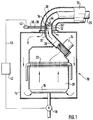
- FIG. 1 shows a schematically illustrated heater
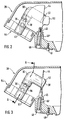
- FIGS. 2 and 3 show longitudinal sections of an exhaust manifold
- FIG. 4 shows a section along line A-A according to FIG. 3
- FIG. 5 shows a front view of the exhaust manifold.
- FIG. 1 schematically shows a so-called room air independent heater or outer wall heater 10 shown, which receives the combustion air via a supply 12 from the outside.
- the heater 10 has a housing 14 which is sealed gas-tight to the surroundings and which is connected to the combustion air supply 12.
- a burner 16 Arranged in the interior of the housing 14 is a burner 16 which is supplied with fuel gas via a gas control valve 18 on the one hand and combustion air via the feed 12 on the other hand.
- the combustion gases generated during the combustion act on a heat exchanger 22 arranged within a combustion chamber 20 for a medium to be heated.
- the exhaust gases are conveyed to the outside by a fan 24 arranged on the exhaust gas side and an exhaust gas discharge, hereinafter referred to as exhaust pipe 26, the combustion air supply 12 being guided coaxially to the exhaust pipe 26.
- exhaust pipe 26 an exhaust gas discharge, hereinafter referred to as exhaust pipe 26, the combustion air supply 12 being guided coaxially to the exhaust pipe 26.
- two transducers 32, 34 surrounded by a measuring tube 30 are arranged at two measuring points 32 ', 34', which are connected via measuring lines 36, 38 to two chambers of a pressure cell 40.
- the chambers of the pressure cell 40 are separated by a membrane, and the pressure cell 40 is also connected to a control unit 42 via a signal line 56.
- a flow restrictor 44 is also arranged in the exhaust manifold 28, which influences the flow resistance in the exhaust pipe 26 in such a way that optimal combustion takes place with constant excess air.
- the flow restrictor 44 is arranged laterally in the exhaust manifold 28 next to the measuring tube 30, the two differential pressure measuring points 32 ′, 34 ′ being arranged upstream of the flow restrictor 44 in the flow direction of the exhaust gas volume flow.
- the flow restrictor can be via a shaft 46 rotatably mounted in the exhaust manifold 28 and fixed by fastening elements 45, 45 ', at one end of which a turntable 48 arranged outside the exhaust manifold 28 is fastened 44 adjust in the exhaust manifold 28.
- the flow resistance in the exhaust pipe 26 can be adapted according to different exhaust pipe lengths and / or different lengths of the combustion air supply 12 so that the combustion air volume flow assumes a value at which the combustion takes place optimally and with a constant excess of air.
- the flow restrictor 44 in the form of a wing can be moved between the positions with the aid of a scale attached to the turntable 48 open “( Figure 2) and closed “(FIG. 3). Corresponding intermediate positions are possible between these two positions.
- An adjusting screw 49 enables the turntable 48 and thus the flow restrictor 44 to be locked.
- the flow restrictor 44 is in the position closed ", for example when using a short exhaust pipe 26, the area of the flow restrictor 44 covers approximately half of the inner diameter of the exhaust manifold 28.
- the heater 10 is started up for the first time the flow restrictor 44 and thus the flow resistance in the exhaust pipe 26 are set by the fitter via the turntable 48.
- An auxiliary throttle 50 additionally formed from the flow restrictor 44 covers one end 52 of the measuring tube 30 more or less depending on the position of the flow restrictor 44 in the exhaust manifold 28.
- the flow restrictor 44 is in the position closed “(FIGS. 3 and 4), the area of the auxiliary throttle 50 covers approximately half of the cross section of the measuring tube 30.
- the measuring tube 30 is arranged within the exhaust manifold 28, which is connected to the blower 24 via a connecting piece 54.
- the measuring tube 30 is formed at right angles, which essentially follows the change in direction of the exhaust pipe 26 caused by the exhaust manifold 28.
- the flow restrictor 44 as seen in the flow direction of the exhaust gas volume flow, is arranged at the rear end of the measuring tube 30, in front of the opening of the end 52 of the measuring tube 30.
- the monitoring device works in the following way:
- the fan 24 When the heater is started up, for example due to a pending heat request, the fan 24 is switched on first. Due to the exhaust gas volume flow conveyed by the blower 24, a differential pressure is detected by the two transducers 32, 34, which, at a predetermined or preset value (approx. 0.6 mbar), deflects the membrane arranged in the pressure transducer 40 to such an extent that in the Pressure sensor 40 arranged contacts are closed and the gas control valve 18 is opened via the signal line 56 and the control unit 42. The ignition is activated at the same time.
- the sensor 32 detects, inter alia, the dynamic pressure resulting from the exhaust gas volume flow, also called dynamic pressure, while the sensor 34 facing away from the exhaust gas volume flow detects the static pressure which remains essentially independent of the exhaust gas volume flow.
- a higher pressure is detected at the measured value sensor 32 than at the measured value sensor 34.
- the exhaust gas volume flow or the combustion air volume flow is constantly monitored via the pressure sensor 40; If the combustion air supply 12 or the exhaust pipe 26 clog or if the blower 14 is defective, the pressure difference drops and the control device 42 closes the gas control valve 18 and the heater 10 is switched off.
- the flow cross section is reduced at this point by the arrangement of the flow restrictor 44 in the exhaust manifold 28. Part of the exhaust gas volume flow is passed through the measuring tube 30, which is laterally offset to the flow restrictor 44, at a higher flow rate.
- the dynamic pressure detected at the transducer 32 is increased, while the pressure at the transducer 34 remains essentially constant, since the flow restrictor 44 is arranged in front of the end 52 of the measuring tube 30 in the flow direction.
- a higher differential pressure is available, which prevents the monitoring device from switching off too early.
- the pressure detected by the transducer 34 is raised with the aid of the auxiliary restrictor 50 acting on the opening of the end 52 of the measuring tube 30 as a function of the position of the flow restrictor .
- measuring tube 30 It is not absolutely necessary to provide a measuring tube 30 for the transducers 32, 34, but it is extremely advantageous and expedient because it achieves better, reproducible measurement results. If the measuring tube 30 is nevertheless dispensed with, an increase in the differential pressure is achieved when the flow restrictor 44 is arranged between the two measuring sensors 32, 34.
Landscapes
- Engineering & Computer Science (AREA)
- Mechanical Engineering (AREA)
- Chemical & Material Sciences (AREA)
- Combustion & Propulsion (AREA)
- General Engineering & Computer Science (AREA)
- General Physics & Mathematics (AREA)
- Fluid Mechanics (AREA)
- Physics & Mathematics (AREA)
- Regulation And Control Of Combustion (AREA)
- General Induction Heating (AREA)
- Yarns And Mechanical Finishing Of Yarns Or Ropes (AREA)
- Devices That Are Associated With Refrigeration Equipment (AREA)
- Control Of Washing Machine And Dryer (AREA)
- Control Of Resistance Heating (AREA)
Abstract
Description
- Die Erfindung betrifft eine Einrichtung zur Überwachung eines Heizgerätes nach der Gattung des Hauptanspruchs. Es sind Heizgeräte (EP 303 550) mit einer Differenzdruck-Meßeinrichtung bekannt, die über mit einer Verbrennungsluft-Zuführung verbundene Druckleitungen den Volumenstrom der Verbrennungsluft bestimmen. Sinkt der Volumenstrom unter einen vorgegebenen Wert, zum Beispiel aufgrund einer Verstopfung der Verbrennungsluft-Zuführung, kann im Sinne eines betriebssicheren Verhaltens das Gasventil des Heizgeräts geschlossen werden. Darüber hinaus verfügen die Heizgeräte der eingangs genannten Art über eine in der Verbrennungsluft-Zuführung oder in einer Abgasabführung angeordnete Strömungsdrossel, die den Strömungswiderstand in der Verbrennungsluft-Zuführung oder in der Abgasabführung so bestimmt, daß bei verschieden langen Abgasabführungen eine optimale Verbrennung mit geringen Schadstoffemissionen und nahezu gleichem Luftüberschuß erfolgt.
- Die erfindungsgemäße Einrichtung zur Überwachung des Volumenstromes der Verbrennungsluft und/oder des Abgases hat den Vorteil, daß bei Heizgeräten mit einer in der Verbrennungsluft-Zuführung oder in der Abgasabführung angeordneten Strömungsdrossel der Differenzdruck so angehoben wird, daß dessen Auswertung nicht zu einer frühzeitigen Abschaltung des Heizgerätes führt und damit eine hohe Betriebssicherheit des Heizgerätes gewährleistet ist.
- Durch die in den Unteransprüchen aufgeführten Maßnahmen sind weitere vorteilhafte Ausgestaltungen der Überwachungseinrichtung nach dem Hauptanspruch möglich.
- Um einer Reduzierung des Differenzdrucks aufgrund der in der Abgasabführung oder in der Verbrennungsluft-Zuführung angeordneten Strömungsdrossel ausreichend entgegenzuwirken, ist es vorteilhaft, die an den beiden Differenzdruck-Meßpunkten angeordneten Meßwertaufnehmer und die Strömungsdrossel, in Strömungsrichtung gesehen, im wesentlichen seitlich nebeneinander anzuordnen.
- Da bei unterschiedlichen Längen der Verbrennungsluft-Zuführung oder der Abgasabführung der Strömungswiderstand verändert wird, ist es notwendig, den Widerstand der Strömungsdrossel entsprechend zu verändern, um unabhängig von der Verbrennungsluft-Zuführung oder Abgasabführung eine optimale Verbrennung mit konstantem Luftüberschuß zu erzielen. Dies wird in vorteilhafter Weise dadurch erreicht, daß die Strömungsdrossel anhand einer von außen zugänglichen Drehscheibe einstellbar ist. Bei einem Heizgerät mit einer kurzen Abgasabführung bzw. einer kurzen Verbrennungsluft-Zuführung wird die Strömungsdrossel so eingestellt, daß deren Strömungswiderstand sehr groß ist, und umgekehrt.
- Eine einfache, funktionell wirksame Ausführung ergibt sich, wenn die Strömungsdrossel über eine mit der Drehscheibe verbundene Welle drehbar gelagert ist.
- Bei der erfindungsgemäßen Überwachungseinrichtung ändert sich der durch die beiden Meßwertaufnehmer erfaßte Differenzdruck in Abhängigkeit vom Strömungswiderstand der Strömungsdrossel. Bei einem hohen Strömungswiderstand besteht die Gefahr, daß die Überwachungseinrichtung aufgrund des zu hohen Anstiegs des Differenzdrucks nicht rechtzeitig abschaltet, beispielsweise, wenn durch ein defektes Gebläse oder durch eine Verstopfung der Zuluft- oder Abgaswege kein ausreichender Luftvolumenstrom gefördert wird. In diesen Fällen wird der Differenzdruck durch eine auf den niederdruckseitigen Meßpunkt wirkende Hilfsdrossel im Sinne einer Absenkung des Differenzdrucks korrigiert.
- Für eine präzise und konstante Druckerfassung durch die Meßwertaufnehmer ist es vorteilhaft, diese in einem in der Verbrennungsluft-Zuführung oder in der Abgasabführung angeordneten Meßrohr unterzubringen.
- Das Meßrohr ist unmittelbar hinter dem Gebläse in einem Abgaskrümmer angeordnet. Da in diesem Bereich eine Richtungsänderung des Abgasvolumenstroms erfolgt, ist das Meßrohr im wesentlichen rechtwinklig ausgebildet und somit der Strömungsänderung angepaßt.
- Bei einer Anordnung der Meßwertaufnehmer in einem Meßrohr wirkt die Hilfsdrossel in vorteilhafter Weise auf das niederdruckseitige Ende des Meßrohres.
- Die Strömungsdrossel und die Hilfsdrossel sind über die Drehscheibe gemeinsam verstellbar, derart, daß mit einer zunehmenden Drosselung des Volumenstromes durch die Strömungsdrossel die Öffnung des niederdruckseitigen Endes des Meßrohres durch die Hilfsdrossel zunehmend abgedeckt wird. Dadurch wird trotz unterschiedlicher Stellungen der Strömungsdrossel in der Verbrennungsluft-Zuführung oder in der Abgasabführung die erfindungsgemäße Differenzdruckerhöhung im wesentlichen konstant gehalten.
- Sind die Meßwertaufnehmer im Meßrohr angebracht, führt eine Anordnung der Strömungsdrossel im gesamten Bereich zwischen den beiden Enden des Meßrohres zu einer Differenzdruckerhöhung.
- Sind die Meßwertaufnehmer ohne Meßrohr direkt in der Verbrennungsluft-Zuführung oder in der Abgasabführung angeordnet, so führt eine Anordnung der Strömungsdrossel im Bereich zwischen den beiden Meßwertaufnehmern zu einer Differenzdruckerhöhung.
- In der Zeichnung ist ein Ausführungsbeispiel der erfindungsgemäßen Überwachungseinrichtung dargestellt und in der nachfolgenden Beschreibung näher erläutert. Es zeigen Figur 1 ein schematisch dargestelltes Heizgerät, Figur 2 und 3 Längsschnitte eines Abgaskrümmers, Figur 4 einen Schnitt nach Linie A-A gemäß Figur 3 und Figur 5 eine Frontansicht des Abgaskrümmers.
- In Figur 1 ist schematisch ein sogenanntes raumluftunabhängiges bzw. Außenwand-Heizgerät 10 dargestellt, das die Verbrennungsluft über eine Zuführung 12 von außen bezieht. Das Heizgerät 10 weist ein zur Umgebung gasdicht abgeschlossenes Gehäuse 14 auf, das mit der Verbrennungsluft-Zuführung 12 verbunden ist. Im Inneren des Gehäuses 14 ist ein Brenner 16 angeordnet, der einerseits über ein Gasregelventil 18 mit Brenngas, und andererseits über die Zuführung 12 mit Verbrennungsluft versorgt wird. Die bei der Verbrennung entstehenden Verbrennungsgase beaufschlagen einen innerhalb einer Verbrennungskammer 20 angeordneten Wärmeübertrager 22 für ein zu erhitzendes Medium. Oberhalb des Wärmeübertragers 22 werden die Abgase durch ein abgasseitig angeordnetes Gebläse 24 und einer Abgasabführung, im folgenden als Abgasrohr 26 bezeichnet, nach außen gefördert, wobei die Verbrennungsluft-Zuführung 12 koaxial zum Abgasrohr 26 geführt ist. In einem Abgaskrümmer 28 des Abgasrohres 26 sind zwei von einem Meßrohr 30 umgebene Meßwertaufnehmer 32, 34 an zwei Meßpunkten 32', 34' angeordnet, die über Meßleitungen 36, 38 mit zwei Kammern einer Druckmeßdose 40 verbunden sind. Die Kammern der Druckmeßdose 40 sind durch eine Membran getrennt, darüberhinaus ist die Druckmeßdose 40 über eine Signalleitung 56 mit einem Steuergerät 42 verbunden.
- Im Abgaskrümmer 28 ist weiterhin eine Strömungsdrossel 44 angeordnet, die den Strömungswiderstand im Abgasrohr 26 so beeinflußt, daß eine optimale Verbrennung mit konstantem Luftüberschuß erfolgt. Die Strömungsdrossel 44 ist im Abgaskrümmer 28 seitlich neben dem Meßrohr 30 angeordnet, wobei die beiden Differenzdruck-Meßpunkte 32', 34' in Strömungsrichtung des Abgasvolumenstroms vor der Strömungsdrossel 44 angeordnet sind. Über eine im Abgaskrümmer 28 drehbar gelagerte und durch Befestigungselemente 45, 45' fixierte Welle 46, an deren einem Ende eine außerhalb des Abgaskrümmers 28 angeordnete Drehscheibe 48 befestigt ist, läßt sich die Strömungsdrossel 44 im Abgaskrümmer 28 verstellen. Damit kann der Strömungswiderstand im Abgasrohr 26 entsprechend unterschiedlichen Abgasrohrlängen und/oder unterschiedlichen Längen der Verbrennungsluft-Zuführung 12 so angepaßt werden, daß der Verbrennungsluft-Volumenstrom einen Wert annimmt, bei dem die Verbrennung optimal und mit konstantem Luftüberschuß erfolgt. Die flügelartig ausgebildete Strömungsdrossel 44 kann mit Hilfe einer auf der Drehscheibe 48 angebrachten Skala zwischen den Positionenoffen" (Figur 2) und
 geschlossen" (Figur 3) verstellt werden. Zwischen diesen beiden Positionen sind entsprechende Zwischenstellungen möglich. Eine Stellschraube 49 ermöglicht dabei eine Arretierung der Drehscheibe 48 und damit der Strömungsdrossel 44. Ist die Strömungsdrossel 44 in der Positiongeschlossen", zum Beispiel bei Verwendung eines kurzen Abgasrohres 26, deckt die Fläche der Strömungsdrossel 44 ca. die Hälfte des Innendurchmessers des Abgaskrümmers 28 ab. In Abhängigkeit von der Länge des Abgasrohres 26 und der Verbrennungsluft-Zuführung 12 wird vor der Erstinbetriebnahme des Heizgeräts 10 durch den Monteur die Strömungsdrossel 44 und damit der Strömungswiderstand im Abgasrohr 26 über die Drehscheibe 48 eingestellt.
 - Eine aus der Strömungsdrossel 44 zusätzlich gebildete Hilfsdrossel 50 deckt in Abhängigkeit von der Stellung der Strömungsdrossel 44 im Abgaskrümmer 28 ein Ende 52 des Meßrohres 30 mehr oder weniger ab. Ist die Strömungsdrossel 44 in der Stellunggeschlossen" (Fig. 3 und 4), so deckt die Fläche der Hilfsdrossel 50 ca. die Hälfte des Querschnitts des Meßrohres 30 ab. Das Meßrohr 30 ist innerhalb des Abgaskrümmers 28 angeordnet, der über einen Anschlußstutzen 54 mit dem Gebläse 24 verbunden ist. Das Meßrohr 30 ist rechtwinklig ausgebildet, womit es im wesentlichen der durch den Abgaskrümmer 28 hervorgerufenen Richtungsänderung des Abgasrohres 26 folgt. Wie aus Figur 2 und 3 ersichtlich, ist die Strömungsdrossel 44, in Strömungsrichtung des Abgasvolumenstromes gesehen, am hinteren Ende des Meßrohres 30, vor der Öffnung des Endes 52 des Meßrohres 30 angeordnet.
- Die Überwachungseinrichtung funktioniert auf folgende Art und Weise:
- Bei der Inbetriebnahme des Heizgerätes, zum Beispiel durch eine anstehende Wärmeanforderung, wird als erstes das Gebläse 24 eingeschaltet. Aufgrund des durch das Gebläse 24 geförderten Abgasvolumenstroms wird durch die beiden Meßwertaufnehmer 32, 34 ein Differenzdruck erfaßt, der bei einem vorgegebenen bzw. voreingestellten Wert (ca. 0,6 mbar) die in der Druckmeßdose 40 angeordnete Membran so weit auslenkt, daß in der Druckmeßdose 40 angeordnete Kontakte geschlossen werden und über die Signalleitung 56 und das Steuergerät 42 das Gasregelventil 18 geöffnet wird. Dabei wird gleichzeitig die Zündung aktiviert. Der Meßwertaufnehmer 32 erfaßt u.a. den durch den Abgasvolumenstrom entstehenden dynamischen Druck, auch Staudruck genannt, während der dem Abgasvolumenstrom abgewandte Meßwertaufnehmer 34 den im wesentlichen unabhängig vom Abgasvolumenstrom gleichbleibenden statischen Druck erfaßt. Am Meßwertaufnehmer 32 wird ein höherer Druck erfaßt, als am Meßwertaufnehmer 34. Während des Betriebs des Heizgerätes 10 wird über die Druckmeßdose 40 ständig der Abgasvolumenstrom bzw. der Verbrennungsluft-Volumenstrom überwacht; setzen sich die Verbrennungsluft-Zuführung 12 oder das Abgasrohr 26 zu oder ist das Gebläse 14 defekt, fällt die Druckdifferenz ab und über das Steuergerät 42 wird das Gasregelventil 18 geschlossen und das Heizgerät 10 abgeschaltet.
- Untersuchungen haben gezeigt, daß der Differenzdruck in Abhängigkeit von der Lage der Strömungsdrossel 44 im Abgasrohr 26 abnimmt, wobei die Gefahr besteht, daß das Heizgerät 10 trotz eines ordnungsgemäßen Betriebs zu früh abschaltet.
- Durch die Anordnung der Strömungsdrossel 44 im Abgaskrümmer 28 wird der Strömungsquerschnitt an dieser Stelle reduziert. Ein Teil des Abgasvolumenstroms wird dabei durch das seitlich zur Strömungsdrossel 44 versetzt angeordnete Meßrohr 30 mit einer höheren Strömungsgeschwindigkeit geleitet. Damit wird der am Meßwertaufnehmer 32 erfaßte Staudruck (dynamischer Druck) vergrößert, während der Druck am Meßwertaufnehmer 34 im wesentlichen konstant bleibt, da die Strömungsdrossel 44 in Strömungsrichtung vor dem Ende 52 des Meßrohres 30 angeordnet ist. Als Ergebnis steht ein höherer Differenzdruck zur Verfügung, der ein zu frühes Abschalten durch die Überwachungseinrichtung verhindert.
- Damit die Differenzdruck-Erhöhung unabhängig von der Stellung der Strömungsdrossel 44 und damit vom Strömungswiderstand konstant bleibt, wird der durch den Meßwertaufnehmer 34 erfaßte Druck mit Hilfe der auf die Öffnung des Endes 52 des Meßrohres 30 wirkenden Hilfsdrossel 50 in Abhängigkeit von der Stellung der Strömungsdrossel angehoben.
- Es ist nicht unbedingt notwendig, ein Meßrohr 30 für die Meßwertaufnehmer 32, 34 vorzusehen, es ist jedoch äußerst vorteilhaft und zweckdienlich, weil dadurch bessere, reproduzierbare Meßergebnisse erzielt werden. Wird dennoch auf das Meßrohr 30 verzichtet, so wird eine Anhebung des Differenzdrucks erreicht, wenn die Strömungsdrossel 44 zwischen den beiden Meßwertaufnehmern 32, 34 angeordnet ist.
Claims (13)
- Einrichtung zur Überwachung des durch ein Gebläse geförderten Volumenstromes der Verbrennungsluft und/oder des Abgases eines Heizgerätes, wobei zwischen mindestens zwei Meßpunkten einer Verbrennungsluftzuführung oder einer Abgasabführung ein Differenzdruck erfaßt wird zur Bestimmung des Volumenstromes der Verbrennungsluft oder des Abgases, mit einer in der Verbrennungsluftzuführung oder in der Abgasabführung angeordneten Strömungsdrossel, dadurch gekennzeichnet, daß die Strömungsdrossel (44) derart angeordnet ist, daß zwischen den beiden Meßpunkten (32', 34') der wirksame Differenzdruck erhöht wird.
- Einrichtung nach Anspruch 1, dadurch gekennzeichnet, daß die Strömungsdrossel (44) und an den beiden Differenzdruck-Meßpunkten (32', 34') angeordnete Meßwertaufnehmer (32, 34) in der Verbrennungsluftzuführung (12) oder in der Abgasabführung (26) im wesentlichen seitlich nebeneinander angeordnet sind.
- Einrichtung nach Anspruch 1 oder 2, dadurch gekennzeichnet, daß die Strömungsdrossel (44) mittels einer außerhalb der Verbrennungsluftzuführung (12) oder der Abgasabführung (26) angeordneten Drehscheibe (48) einstellbar ist.
- Einrichtung nach einem der vorhergehenden Ansprüche, dadurch gekennzeichnet, daß die Strömungsdrossel (44) drehbar gelagert und über eine mit der Drehscheibe (48) verbundene Welle (46) verstellbar ist.
- Einrichtung nach einem der vorhergehenden Ansprüche, gekennzeichnet durch eine zusätzliche, auf den niederdruckseitigen Meßpunkt (34') wirkende Hilfdrossel (50).
- Einrichtung nach einem der Ansprüche 2 bis 5, dadurch gekennzeichnet, daß die Meßwertaufnehmer (32, 34) in einem in der Verbrennungsluftzuführung (12) oder in der Abgasabführung (26) angeordneten Meßrohr (30) angeordnet sind.
- Einrichtung nach Anspruch 6, dadurch gekennzeichnet, daß das Meßrohr (30) rechtwinklig ausgebildet ist und in einem Abgaskrümmer (28) der Abgasabführung (26) hinter dem Gebläse (14) angeordnet ist.
- Einrichtung nach Anspruch 6 oder 7, dadurch gekennzeichnet, daß die Hilfsdrossel (50) auf das niederdruckseitige Ende (52) des Meßrohres (30) wirkt.
- Einrichtung nach Anspruch 8, dadurch gekennzeichnet, daß die Hilfsdrossel (50) maximal die Hälfte des Querschnitts des Meßrohres (30) abdeckt.
- Einrichtung nach einem der Ansprüche 5 bis 9, dadurch gekennzeichnet, daß die Hilfsdrossel (50) gemeinsam mit der Strömungsdrossel (44) verstellbar ist.
- Einrichtung nach einem der Ansprüche 6 bis 10, dadurch gekennzeichnet, daß die Strömungsdrossel (44) im Bereich zwischen den beiden Enden (52, 53) des Meßrohres (30) angeordnet ist.
- Einrichtung nach einem der Ansprüche 1 bis 5, dadurch gekennzeichnet, daß die Strömungsdrossel (44) im Bereich zwischen den beiden Meßpunkten (32', 34') angeordnet ist.
- Einrichtung nach einem der vorhergehenden Ansprüche, dadurch gekennzeichnet, daß das Verhältnis der Querschnitte der Abgasabführung (26) und der Strömungsdrossel (44) circa 4:2 bis 4:3 beträgt.
Applications Claiming Priority (2)
| Application Number | Priority Date | Filing Date | Title |
|---|---|---|---|
| DE19605380A DE19605380A1 (de) | 1996-02-14 | 1996-02-14 | Einrichtung zur Überwachung eines Heizgerätes |
| DE19605380 | 1996-02-14 |
Publications (2)
| Publication Number | Publication Date |
|---|---|
| EP0790465A1 true EP0790465A1 (de) | 1997-08-20 |
| EP0790465B1 EP0790465B1 (de) | 2001-10-31 |
Family
ID=7785341
Family Applications (1)
| Application Number | Title | Priority Date | Filing Date |
|---|---|---|---|
| EP96121009A Expired - Lifetime EP0790465B1 (de) | 1996-02-14 | 1996-12-31 | Einrichtung zur Überwachung eines Heizgerätes |
Country Status (6)
| Country | Link |
|---|---|
| EP (1) | EP0790465B1 (de) |
| AT (1) | ATE208026T1 (de) |
| DE (2) | DE19605380A1 (de) |
| ES (1) | ES2166857T3 (de) |
| PT (1) | PT790465E (de) |
| TR (1) | TR199700070A2 (de) |
Cited By (5)
| Publication number | Priority date | Publication date | Assignee | Title |
|---|---|---|---|---|
| EP1130319A1 (de) * | 2000-03-03 | 2001-09-05 | IABER S.p.A. | Venturiohr |
| EP1046864A3 (de) * | 1999-03-23 | 2002-09-04 | L.N. di NATALINI LINO & C. - S.r.l. | Venturigerät für Gaskessel mit geschlossener Brennkammer |
| EP1434017A1 (de) * | 2002-12-23 | 2004-06-30 | MERLONI TERMOSANITARI S.p.A. | Wandmontierter Gebläseheizkessel |
| EP1434016A1 (de) * | 2002-12-23 | 2004-06-30 | MERLONI TERMOSANITARI S.p.A. | Druckschalter für einen geschlossenen Gebläseheizkessel |
| WO2013107021A1 (zh) * | 2012-01-19 | 2013-07-25 | 中山大洋电机股份有限公司 | 一种调节测压接口负压值的风机结构 |
Families Citing this family (4)
| Publication number | Priority date | Publication date | Assignee | Title |
|---|---|---|---|---|
| DE19961286C2 (de) * | 1999-12-18 | 2001-12-13 | Bosch Gmbh Robert | Verfahren zum Regeln eines Wärmeerzeugers mit einer Luft-Abgas-Führung |
| DE19961285C1 (de) * | 1999-12-18 | 2001-06-28 | Bosch Gmbh Robert | Verfahren zum Regeln eines Wärmeerzeugers mit einer Luft-Abgas-Führung |
| JP2004204792A (ja) | 2002-12-26 | 2004-07-22 | Aisan Ind Co Ltd | 内燃機関の吸気装置 |
| DE102010054807B4 (de) * | 2010-12-16 | 2015-07-02 | Honeywell Technologies Sarl | Verfahren zum Betreiben einer Gasbrennervorrichtung |
Citations (6)
| Publication number | Priority date | Publication date | Assignee | Title |
|---|---|---|---|---|
| US2463473A (en) * | 1945-07-07 | 1949-03-01 | Walter M Boothby | Flowmeter |
| US4094632A (en) * | 1977-02-07 | 1978-06-13 | John Zink Company | Accelerated response for delivery of smoke suppressant to flares |
| DE3333606A1 (de) * | 1982-09-15 | 1984-03-15 | Joh. Vaillant Gmbh U. Co, 5630 Remscheid | Brennstoffbeheizte waermequelle |
| EP0291583A1 (de) * | 1986-01-31 | 1988-11-23 | Apparatenfabriek ATAG B.V. | Heizgerät |
| EP0303550A2 (de) | 1987-08-12 | 1989-02-15 | Rhone-Poulenc Chimie | Verfahren zur Herstellung von 2-Methyl-Pentandiamin durch Hydrogenierung von 2-Methyl-Glutaronitril |
| EP0370557A1 (de) * | 1988-11-22 | 1990-05-30 | Ems Holland B.V. | Durchflussmesser für Gas |
Family Cites Families (2)
| Publication number | Priority date | Publication date | Assignee | Title |
|---|---|---|---|---|
| DE29504705U1 (de) * | 1995-03-24 | 1996-07-25 | Robert Bosch Gmbh, 70469 Stuttgart | Regelvorrichtung für einen Brenner mit einem Gebläse für die Verbrennungsluft |
| DE19545948C2 (de) * | 1995-12-08 | 1997-09-18 | Waldner Laboreinrichtungen | Vorrichtung zum Bestimmen der Stärke eines Gasvolumenstroms |
-
1996
- 1996-02-14 DE DE19605380A patent/DE19605380A1/de not_active Withdrawn
- 1996-12-31 EP EP96121009A patent/EP0790465B1/de not_active Expired - Lifetime
- 1996-12-31 PT PT96121009T patent/PT790465E/pt unknown
- 1996-12-31 AT AT96121009T patent/ATE208026T1/de not_active IP Right Cessation
- 1996-12-31 DE DE59608063T patent/DE59608063D1/de not_active Expired - Lifetime
- 1996-12-31 ES ES96121009T patent/ES2166857T3/es not_active Expired - Lifetime
-
1997
- 1997-01-31 TR TR97/00070A patent/TR199700070A2/xx unknown
Patent Citations (6)
| Publication number | Priority date | Publication date | Assignee | Title |
|---|---|---|---|---|
| US2463473A (en) * | 1945-07-07 | 1949-03-01 | Walter M Boothby | Flowmeter |
| US4094632A (en) * | 1977-02-07 | 1978-06-13 | John Zink Company | Accelerated response for delivery of smoke suppressant to flares |
| DE3333606A1 (de) * | 1982-09-15 | 1984-03-15 | Joh. Vaillant Gmbh U. Co, 5630 Remscheid | Brennstoffbeheizte waermequelle |
| EP0291583A1 (de) * | 1986-01-31 | 1988-11-23 | Apparatenfabriek ATAG B.V. | Heizgerät |
| EP0303550A2 (de) | 1987-08-12 | 1989-02-15 | Rhone-Poulenc Chimie | Verfahren zur Herstellung von 2-Methyl-Pentandiamin durch Hydrogenierung von 2-Methyl-Glutaronitril |
| EP0370557A1 (de) * | 1988-11-22 | 1990-05-30 | Ems Holland B.V. | Durchflussmesser für Gas |
Cited By (5)
| Publication number | Priority date | Publication date | Assignee | Title |
|---|---|---|---|---|
| EP1046864A3 (de) * | 1999-03-23 | 2002-09-04 | L.N. di NATALINI LINO & C. - S.r.l. | Venturigerät für Gaskessel mit geschlossener Brennkammer |
| EP1130319A1 (de) * | 2000-03-03 | 2001-09-05 | IABER S.p.A. | Venturiohr |
| EP1434017A1 (de) * | 2002-12-23 | 2004-06-30 | MERLONI TERMOSANITARI S.p.A. | Wandmontierter Gebläseheizkessel |
| EP1434016A1 (de) * | 2002-12-23 | 2004-06-30 | MERLONI TERMOSANITARI S.p.A. | Druckschalter für einen geschlossenen Gebläseheizkessel |
| WO2013107021A1 (zh) * | 2012-01-19 | 2013-07-25 | 中山大洋电机股份有限公司 | 一种调节测压接口负压值的风机结构 |
Also Published As
| Publication number | Publication date |
|---|---|
| TR199700070A2 (tr) | 1997-08-21 |
| EP0790465B1 (de) | 2001-10-31 |
| ES2166857T3 (es) | 2002-05-01 |
| PT790465E (pt) | 2002-03-28 |
| ATE208026T1 (de) | 2001-11-15 |
| DE19605380A1 (de) | 1997-08-21 |
| DE59608063D1 (de) | 2001-12-06 |
Similar Documents
| Publication | Publication Date | Title |
|---|---|---|
| EP1084369B1 (de) | Regeleinrichtung für gasbrenner | |
| DE19740666C1 (de) | Regelvorrichtung für das Einhalten eines geforderten Gas-/Luft-Verhältnisses für Gasbrenner | |
| EP1510756A1 (de) | Verhältnisregler mit Dynamischer Verhältnisbildung | |
| EP0356690B1 (de) | Brennstoffbefeuerter Wärmeerzeuger | |
| EP0282758B1 (de) | Ventilanordnung | |
| EP0790465B1 (de) | Einrichtung zur Überwachung eines Heizgerätes | |
| DE2153877C3 (de) | Turbulenzverstärker | |
| EP0390964B1 (de) | Regeleinrichtung für Gasbrenner | |
| DE2550826B2 (de) | Abgasrückführeinrichtung für eine Brennkraftmaschine | |
| DE69926287T2 (de) | Entspannungsventil | |
| DE19724861C1 (de) | Gasbrenner für einen Heizkessel | |
| EP0505714B1 (de) | Regelvorrichtung für Gasbrenner mit einem Gebläse zum Zuführen von Verbrennungsluft | |
| DE19639992B4 (de) | Verfahren zum Steuern des Gasdurchsatzes | |
| DE8714327U1 (de) | Verschraubung für Rohr- und/oder Schlauchleitungen | |
| DE19501203C2 (de) | Regeleinrichtung im Wasserdurchlauf eines Durchlauferhitzers | |
| DE4427846C2 (de) | Regeleinrichtung für die Temperatur des aus einer Wasserleitung entnommenen Wassers | |
| EP2908055B1 (de) | Gasventil mit integriertem luftdruckwächter | |
| DE2308333A1 (de) | Regelventil | |
| CH689458A5 (de) | Brenner. | |
| DE10062681C2 (de) | Flüssigkeitsventil für Heiz- und/oder Kühlanlagen | |
| DE3026826C2 (de) | Kraftstoffeinspritzvorrichtung für eine fremdgezündete Kolbenbrennkraftmaschine | |
| EP0479216B1 (de) | Heizeinrichtung | |
| AT395773B (de) | Heizeinrichtung | |
| AT402441B (de) | Einrichtung zur druckmessung an einer gebläseunterstützten heizeinrichtung | |
| DE2831593C2 (de) | Brennstoff-Zuführeinrichtung für eine Brennkraftmaschine |
Legal Events
| Date | Code | Title | Description |
|---|---|---|---|
| PUAI | Public reference made under article 153(3) epc to a published international application that has entered the european phase |
Free format text: ORIGINAL CODE: 0009012 |
|
| AK | Designated contracting states |
Kind code of ref document: A1 Designated state(s): AT CH DE ES FR GB IT LI NL PT |
|
| 17P | Request for examination filed |
Effective date: 19980220 |
|
| 17Q | First examination report despatched |
Effective date: 19990208 |
|
| GRAG | Despatch of communication of intention to grant |
Free format text: ORIGINAL CODE: EPIDOS AGRA |
|
| GRAG | Despatch of communication of intention to grant |
Free format text: ORIGINAL CODE: EPIDOS AGRA |
|
| GRAH | Despatch of communication of intention to grant a patent |
Free format text: ORIGINAL CODE: EPIDOS IGRA |
|
| GRAH | Despatch of communication of intention to grant a patent |
Free format text: ORIGINAL CODE: EPIDOS IGRA |
|
| GRAA | (expected) grant |
Free format text: ORIGINAL CODE: 0009210 |
|
| AK | Designated contracting states |
Kind code of ref document: B1 Designated state(s): AT CH DE ES FR GB IT LI NL PT |
|
| PG25 | Lapsed in a contracting state [announced via postgrant information from national office to epo] |
Ref country code: NL Free format text: LAPSE BECAUSE OF FAILURE TO SUBMIT A TRANSLATION OF THE DESCRIPTION OR TO PAY THE FEE WITHIN THE PRESCRIBED TIME-LIMIT Effective date: 20011031 |
|
| REF | Corresponds to: |
Ref document number: 208026 Country of ref document: AT Date of ref document: 20011115 Kind code of ref document: T |
|
| REG | Reference to a national code |
Ref country code: CH Ref legal event code: EP |
|
| REF | Corresponds to: |
Ref document number: 59608063 Country of ref document: DE Date of ref document: 20011206 |
|
| PGFP | Annual fee paid to national office [announced via postgrant information from national office to epo] |
Ref country code: GB Payment date: 20011210 Year of fee payment: 6 |
|
| PGFP | Annual fee paid to national office [announced via postgrant information from national office to epo] |
Ref country code: FR Payment date: 20011219 Year of fee payment: 6 Ref country code: ES Payment date: 20011219 Year of fee payment: 6 |
|
| PGFP | Annual fee paid to national office [announced via postgrant information from national office to epo] |
Ref country code: CH Payment date: 20011221 Year of fee payment: 6 Ref country code: AT Payment date: 20011221 Year of fee payment: 6 |
|
| PGFP | Annual fee paid to national office [announced via postgrant information from national office to epo] |
Ref country code: NL Payment date: 20011227 Year of fee payment: 6 |
|
| REG | Reference to a national code |
Ref country code: GB Ref legal event code: IF02 |
|
| PGFP | Annual fee paid to national office [announced via postgrant information from national office to epo] |
Ref country code: PT Payment date: 20020103 Year of fee payment: 6 |
|
| ET | Fr: translation filed | ||
| GBT | Gb: translation of ep patent filed (gb section 77(6)(a)/1977) |
Effective date: 20020130 |
|
| REG | Reference to a national code |
Ref country code: PT Ref legal event code: SC4A Free format text: AVAILABILITY OF NATIONAL TRANSLATION Effective date: 20011219 |
|
| NLV1 | Nl: lapsed or annulled due to failure to fulfill the requirements of art. 29p and 29m of the patents act | ||
| REG | Reference to a national code |
Ref country code: ES Ref legal event code: FG2A Ref document number: 2166857 Country of ref document: ES Kind code of ref document: T3 |
|
| PLBE | No opposition filed within time limit |
Free format text: ORIGINAL CODE: 0009261 |
|
| STAA | Information on the status of an ep patent application or granted ep patent |
Free format text: STATUS: NO OPPOSITION FILED WITHIN TIME LIMIT |
|
| 26N | No opposition filed | ||
| PG25 | Lapsed in a contracting state [announced via postgrant information from national office to epo] |
Ref country code: LI Free format text: LAPSE BECAUSE OF NON-PAYMENT OF DUE FEES Effective date: 20021231 Ref country code: GB Free format text: LAPSE BECAUSE OF NON-PAYMENT OF DUE FEES Effective date: 20021231 Ref country code: CH Free format text: LAPSE BECAUSE OF NON-PAYMENT OF DUE FEES Effective date: 20021231 Ref country code: AT Free format text: LAPSE BECAUSE OF NON-PAYMENT OF DUE FEES Effective date: 20021231 |
|
| PG25 | Lapsed in a contracting state [announced via postgrant information from national office to epo] |
Ref country code: ES Free format text: LAPSE BECAUSE OF NON-PAYMENT OF DUE FEES Effective date: 20030102 |
|
| PG25 | Lapsed in a contracting state [announced via postgrant information from national office to epo] |
Ref country code: PT Free format text: LAPSE BECAUSE OF NON-PAYMENT OF DUE FEES Effective date: 20030630 |
|
| REG | Reference to a national code |
Ref country code: CH Ref legal event code: PL |
|
| GBPC | Gb: european patent ceased through non-payment of renewal fee |
Effective date: 20021231 |
|
| PG25 | Lapsed in a contracting state [announced via postgrant information from national office to epo] |
Ref country code: FR Free format text: LAPSE BECAUSE OF NON-PAYMENT OF DUE FEES Effective date: 20030901 |
|
| REG | Reference to a national code |
Ref country code: PT Ref legal event code: MM4A Free format text: LAPSE DUE TO NON-PAYMENT OF FEES Effective date: 20030630 |
|
| REG | Reference to a national code |
Ref country code: FR Ref legal event code: ST |
|
| REG | Reference to a national code |
Ref country code: ES Ref legal event code: FD2A Effective date: 20030102 |
|
| PG25 | Lapsed in a contracting state [announced via postgrant information from national office to epo] |
Ref country code: IT Free format text: LAPSE BECAUSE OF NON-PAYMENT OF DUE FEES Effective date: 20051231 |
|
| PGFP | Annual fee paid to national office [announced via postgrant information from national office to epo] |
Ref country code: DE Payment date: 20160224 Year of fee payment: 20 |
|
| REG | Reference to a national code |
Ref country code: DE Ref legal event code: R071 Ref document number: 59608063 Country of ref document: DE |