EP0790488A2 - Levier de commande à positionner en rotation tri-axiale - Google Patents
Levier de commande à positionner en rotation tri-axiale Download PDFInfo
- Publication number
- EP0790488A2 EP0790488A2 EP97101788A EP97101788A EP0790488A2 EP 0790488 A2 EP0790488 A2 EP 0790488A2 EP 97101788 A EP97101788 A EP 97101788A EP 97101788 A EP97101788 A EP 97101788A EP 0790488 A2 EP0790488 A2 EP 0790488A2
- Authority
- EP
- European Patent Office
- Prior art keywords
- light
- joystick
- light beams
- detector
- control stick
- Prior art date
- Legal status (The legal status is an assumption and is not a legal conclusion. Google has not performed a legal analysis and makes no representation as to the accuracy of the status listed.)
- Granted
Links
Images

Classifications
-
- G—PHYSICS
- G06—COMPUTING OR CALCULATING; COUNTING
- G06F—ELECTRIC DIGITAL DATA PROCESSING
- G06F3/00—Input arrangements for transferring data to be processed into a form capable of being handled by the computer; Output arrangements for transferring data from processing unit to output unit, e.g. interface arrangements
- G06F3/01—Input arrangements or combined input and output arrangements for interaction between user and computer
- G06F3/03—Arrangements for converting the position or the displacement of a member into a coded form
- G06F3/0304—Detection arrangements using opto-electronic means
- G06F3/0325—Detection arrangements using opto-electronic means using a plurality of light emitters or reflectors or a plurality of detectors forming a reference frame from which to derive the orientation of the object, e.g. by triangulation or on the basis of reference deformation in the picked up image
-
- G—PHYSICS
- G01—MEASURING; TESTING
- G01D—MEASURING NOT SPECIALLY ADAPTED FOR A SPECIFIC VARIABLE; ARRANGEMENTS FOR MEASURING TWO OR MORE VARIABLES NOT COVERED IN A SINGLE OTHER SUBCLASS; TARIFF METERING APPARATUS; MEASURING OR TESTING NOT OTHERWISE PROVIDED FOR
- G01D5/00—Mechanical means for transferring the output of a sensing member; Means for converting the output of a sensing member to another variable where the form or nature of the sensing member does not constrain the means for converting; Transducers not specially adapted for a specific variable
- G01D5/26—Mechanical means for transferring the output of a sensing member; Means for converting the output of a sensing member to another variable where the form or nature of the sensing member does not constrain the means for converting; Transducers not specially adapted for a specific variable characterised by optical transfer means, i.e. using infrared, visible, or ultraviolet light
-
- G—PHYSICS
- G05—CONTROLLING; REGULATING
- G05G—CONTROL DEVICES OR SYSTEMS INSOFAR AS CHARACTERISED BY MECHANICAL FEATURES ONLY
- G05G9/00—Manually-actuated control mechanisms provided with one single controlling member co-operating with two or more controlled members, e.g. selectively, simultaneously
- G05G9/02—Manually-actuated control mechanisms provided with one single controlling member co-operating with two or more controlled members, e.g. selectively, simultaneously the controlling member being movable in different independent ways, movement in each individual way actuating one controlled member only
- G05G9/04—Manually-actuated control mechanisms provided with one single controlling member co-operating with two or more controlled members, e.g. selectively, simultaneously the controlling member being movable in different independent ways, movement in each individual way actuating one controlled member only in which movement in two or more ways can occur simultaneously
- G05G9/047—Manually-actuated control mechanisms provided with one single controlling member co-operating with two or more controlled members, e.g. selectively, simultaneously the controlling member being movable in different independent ways, movement in each individual way actuating one controlled member only in which movement in two or more ways can occur simultaneously the controlling member being movable by hand about orthogonal axes, e.g. joysticks
- G05G2009/0474—Manually-actuated control mechanisms provided with one single controlling member co-operating with two or more controlled members, e.g. selectively, simultaneously the controlling member being movable in different independent ways, movement in each individual way actuating one controlled member only in which movement in two or more ways can occur simultaneously the controlling member being movable by hand about orthogonal axes, e.g. joysticks characterised by means converting mechanical movement into electric signals
- G05G2009/04759—Light-sensitive detector, e.g. photoelectric
-
- G—PHYSICS
- G05—CONTROLLING; REGULATING
- G05G—CONTROL DEVICES OR SYSTEMS INSOFAR AS CHARACTERISED BY MECHANICAL FEATURES ONLY
- G05G9/00—Manually-actuated control mechanisms provided with one single controlling member co-operating with two or more controlled members, e.g. selectively, simultaneously
- G05G9/02—Manually-actuated control mechanisms provided with one single controlling member co-operating with two or more controlled members, e.g. selectively, simultaneously the controlling member being movable in different independent ways, movement in each individual way actuating one controlled member only
- G05G9/04—Manually-actuated control mechanisms provided with one single controlling member co-operating with two or more controlled members, e.g. selectively, simultaneously the controlling member being movable in different independent ways, movement in each individual way actuating one controlled member only in which movement in two or more ways can occur simultaneously
- G05G9/047—Manually-actuated control mechanisms provided with one single controlling member co-operating with two or more controlled members, e.g. selectively, simultaneously the controlling member being movable in different independent ways, movement in each individual way actuating one controlled member only in which movement in two or more ways can occur simultaneously the controlling member being movable by hand about orthogonal axes, e.g. joysticks
- G05G2009/04781—Manually-actuated control mechanisms provided with one single controlling member co-operating with two or more controlled members, e.g. selectively, simultaneously the controlling member being movable in different independent ways, movement in each individual way actuating one controlled member only in which movement in two or more ways can occur simultaneously the controlling member being movable by hand about orthogonal axes, e.g. joysticks with additional rotation of the controlling member
-
- Y—GENERAL TAGGING OF NEW TECHNOLOGICAL DEVELOPMENTS; GENERAL TAGGING OF CROSS-SECTIONAL TECHNOLOGIES SPANNING OVER SEVERAL SECTIONS OF THE IPC; TECHNICAL SUBJECTS COVERED BY FORMER USPC CROSS-REFERENCE ART COLLECTIONS [XRACs] AND DIGESTS
- Y10—TECHNICAL SUBJECTS COVERED BY FORMER USPC
- Y10T—TECHNICAL SUBJECTS COVERED BY FORMER US CLASSIFICATION
- Y10T74/00—Machine element or mechanism
- Y10T74/20—Control lever and linkage systems
- Y10T74/20012—Multiple controlled elements
- Y10T74/20201—Control moves in two planes
Definitions
- the invention relates to a triaxially rotatable joystick, in particular for a helicopter, with an electronic sensor for determining the joystick position.
- an opto-electronic position transmitter is known from US Pat. No. 3,432,671, in which a rectangular light field is imaged on a sensor part consisting of four photocells arranged in a cruciform manner via a biaxially tiltable deflecting mirror, and the swivel position of the deflecting mirror with respect to the size of the illuminated surface portions two axes of rotation is calculated.
- a sensor is unsuitable for determining the position of a three-axis adjustable joystick and also has the disadvantage of a limited measuring accuracy because external interference, e.g. local fluctuations in the lighting intensity have a falsifying effect on the measurement result.
- the object of the invention is to design a joystick of the type mentioned in such a way that an extremely precise and reliable position measurement with respect to all three axes of movement of the joystick is guaranteed in a structurally simple, weight-saving and space-saving manner.
- the detector mosaic advantageously consists of two mutually separate detector fields, each of which is located in the beam path only one of the two light beams.
- the detector mosaic or the detector fields are preferably flat according to claim 4.
- the mutual position of the two light beams and, if applicable, the detector fields can be chosen practically as desired, depending on the installation conditions.
- the two light beams can be inclined, preferably aligned perpendicular to one another, which is recommended for a multiple redundant sensor system. in general, however, a substantially parallel mutual alignment of the two light beams is preferred.
- the light beams are generated by two light-emitting diodes fastened to the control stick.
- a light-emitting single diode with a downstream radiation splitter in order to generate the double beam.
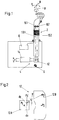
- a joystick 2 is triaxial about a fictitious hinge point G, namely on the one hand about the vertical axis H and on the other hand in the longitudinal and lateral control direction N or R limited rotary position and contains an overall designated 4, opto-electronic sensor, softer the joystick position measures in all three axes and supplies corresponding electrical control commands n, r and h, for example for a downstream, fly-by-wire controlled blade angle adjustment system of a helicopter and for the control force simulation of the control stick 2.
- the sensor 4 contains two laser diodes 8.1 and 8.2, which are fastened in the interior of the control stick 2 and are connected to a power supply 6, including a focusing device for generating two spatially separated, sharply focused laser light beams 10.1 and 10.2, which run parallel to one another and of which one - 10.1 - is aligned with the vertical axis H.
- a single diode with a downstream radiation splitter can also be provided to generate the double beam 10.
- a detector mosaic 12 fixed to the housing in the form of a high-resolution, laser light-sensitive CCD detector, which lies over the entire adjustment range of the joystick 2 in the beam path of the two light beams 10.1 and 10.2 and the position of the light points P 1 generated by them on the detector surface , P 2 determined and transfers the corresponding X and Y coordinates to a downstream evaluation electronics 14, where they are converted into the raw, pitch and yaw commands r, n and h of the control stick 2 in the manner explained below.
- the light beams 10.1 and 10.2 can also have any other desired orientation to one another and to the vertical axis H.
- all that is required to adjust the sensor 2 is to store the coordinates of the two light spots P 1 and P 2 in the zero position and in a second control stick position in the evaluation electronics 14, which position is twisted only about the vertical axis H, and the Relationships given above between the measured values of the detector mosaic 12 and the output signals n, r and h to be modified accordingly.
- the detector mosaic 12 is of flat design. The consequence of this is that the distance between the two light spots P 1 and P 2 changes slightly when the control stick 2 is pivoted, which can be taken into account by corresponding correction factors, for example in the form of tables in the evaluation electronics 14. If the adjustment movements of the control stick 2 are smaller than the mutual distance of the light beams 10.1 and 10.2, the light spots P 1 and P 2 each remain in separate surface areas. In order to save light-sensitive detector area, the detector mosaic 12 is therefore composed of two mutually separate detector fields 12A and 12B, which correspond in shape and size to the parts of the area migrated by the light spots P 1 and P 2 .
- a control stick 102 is shown with a sensor system 104 that is multiple, namely four times redundant. Accordingly, a total of four double beams 110 are generated by a corresponding plurality of laser diodes 108, each of which strikes one of four detector mosaics 112 grouped around the vertical axis H of the control stick 102.
- the position coordinates of the pair of light spots created on the individual detector mosaics 112 are transmitted to a common evaluation electronics 114, from which the roll, pitch and yaw position of the control stick are derived from them 102 is calculated.
- the evaluation electronics 114 is designed such that the sensor remains fully functional in the event of failure of individual sensor components. Otherwise, the construction and mode of operation is the same as in the exemplary embodiment according to FIGS. 1 and 2.
- the second light beam 210.2 generated by the laser light diode 208.2 is directed essentially radially to the joystick 202 onto the detector field 212B, which in this case is attached to the housing next to the joystick 202.
- the detector field 212B can also be arranged laterally next to it in the plane of the detector field 212A in the same way as in the first exemplary embodiment, and a deflection mirror can be provided instead of the detector field 212B, which deflects the laterally directed laser light beam 210.2 downward onto the detector field 212B.
- the evaluation electronics work on the basis of correspondingly modified arithmetic operations for converting the light spot position coordinates into the position signals r, n and h of the control stick 202. Otherwise, the construction and function are the same as in the exemplary embodiments described above.
Landscapes
- Engineering & Computer Science (AREA)
- Physics & Mathematics (AREA)
- General Physics & Mathematics (AREA)
- General Engineering & Computer Science (AREA)
- Theoretical Computer Science (AREA)
- Human Computer Interaction (AREA)
- Position Input By Displaying (AREA)
- Mechanical Control Devices (AREA)
- Length Measuring Devices By Optical Means (AREA)
Applications Claiming Priority (2)
| Application Number | Priority Date | Filing Date | Title |
|---|---|---|---|
| DE19605573A DE19605573C2 (de) | 1996-02-15 | 1996-02-15 | Dreiachsig drehpositionierbarer Steuerknüppel |
| DE19605573 | 1996-02-15 |
Publications (3)
| Publication Number | Publication Date |
|---|---|
| EP0790488A2 true EP0790488A2 (fr) | 1997-08-20 |
| EP0790488A3 EP0790488A3 (fr) | 1999-05-19 |
| EP0790488B1 EP0790488B1 (fr) | 2003-05-02 |
Family
ID=7785464
Family Applications (1)
| Application Number | Title | Priority Date | Filing Date |
|---|---|---|---|
| EP97101788A Expired - Lifetime EP0790488B1 (fr) | 1996-02-15 | 1997-02-05 | Levier de commande à positionner en rotation tri-axiale |
Country Status (3)
| Country | Link |
|---|---|
| US (1) | US6081257A (fr) |
| EP (1) | EP0790488B1 (fr) |
| DE (2) | DE19605573C2 (fr) |
Cited By (2)
| Publication number | Priority date | Publication date | Assignee | Title |
|---|---|---|---|---|
| WO2005088419A1 (fr) | 2004-03-15 | 2005-09-22 | Technische Universiteit Delft | Manette de jeu |
| WO2017037048A1 (fr) * | 2015-08-31 | 2017-03-09 | Niels Buchhold | Dispositif et procédé de détermination de position triaxiale d'un élément d'absorption de force |
Families Citing this family (32)
| Publication number | Priority date | Publication date | Assignee | Title |
|---|---|---|---|---|
| DE19821403B4 (de) | 1998-05-13 | 2005-07-28 | ZF Lemförder Metallwaren AG | Wählvorrichtung für ein Fahrzeuggetriebe |
| US8412377B2 (en) | 2000-01-24 | 2013-04-02 | Irobot Corporation | Obstacle following sensor scheme for a mobile robot |
| US8788092B2 (en) | 2000-01-24 | 2014-07-22 | Irobot Corporation | Obstacle following sensor scheme for a mobile robot |
| US6956348B2 (en) | 2004-01-28 | 2005-10-18 | Irobot Corporation | Debris sensor for cleaning apparatus |
| US7571511B2 (en) | 2002-01-03 | 2009-08-11 | Irobot Corporation | Autonomous floor-cleaning robot |
| US6690134B1 (en) | 2001-01-24 | 2004-02-10 | Irobot Corporation | Method and system for robot localization and confinement |
| US7663333B2 (en) | 2001-06-12 | 2010-02-16 | Irobot Corporation | Method and system for multi-mode coverage for an autonomous robot |
| US8396592B2 (en) | 2001-06-12 | 2013-03-12 | Irobot Corporation | Method and system for multi-mode coverage for an autonomous robot |
| DE10139878A1 (de) * | 2001-08-10 | 2003-03-06 | Eckart Uhlmann | Einrichtung zur Erfassung der Relativposition zweier zueinander bewegbarer Körper |
| US9128486B2 (en) | 2002-01-24 | 2015-09-08 | Irobot Corporation | Navigational control system for a robotic device |
| US8428778B2 (en) | 2002-09-13 | 2013-04-23 | Irobot Corporation | Navigational control system for a robotic device |
| US8386081B2 (en) | 2002-09-13 | 2013-02-26 | Irobot Corporation | Navigational control system for a robotic device |
| US7332890B2 (en) | 2004-01-21 | 2008-02-19 | Irobot Corporation | Autonomous robot auto-docking and energy management systems and methods |
| EP1776623B1 (fr) | 2004-06-24 | 2011-12-07 | iRobot Corporation | Programmateur a telecommande et procede de telecommande pour dispositif robotique autonome |
| US8972052B2 (en) | 2004-07-07 | 2015-03-03 | Irobot Corporation | Celestial navigation system for an autonomous vehicle |
| US7706917B1 (en) | 2004-07-07 | 2010-04-27 | Irobot Corporation | Celestial navigation system for an autonomous robot |
| US7620476B2 (en) | 2005-02-18 | 2009-11-17 | Irobot Corporation | Autonomous surface cleaning robot for dry cleaning |
| US8392021B2 (en) | 2005-02-18 | 2013-03-05 | Irobot Corporation | Autonomous surface cleaning robot for wet cleaning |
| AU2006214016B2 (en) | 2005-02-18 | 2011-11-10 | Irobot Corporation | Autonomous surface cleaning robot for wet and dry cleaning |
| US8930023B2 (en) | 2009-11-06 | 2015-01-06 | Irobot Corporation | Localization by learning of wave-signal distributions |
| EP2816434A3 (fr) | 2005-12-02 | 2015-01-28 | iRobot Corporation | Robot à couverture autonome |
| EP2065774B1 (fr) | 2005-12-02 | 2013-10-23 | iRobot Corporation | Système de navigation pour robot autonome de couverture |
| KR101099808B1 (ko) | 2005-12-02 | 2011-12-27 | 아이로보트 코퍼레이션 | 로봇 시스템 |
| ES2413862T3 (es) | 2005-12-02 | 2013-07-17 | Irobot Corporation | Robot modular |
| EP2120122B1 (fr) | 2005-12-02 | 2013-10-30 | iRobot Corporation | Mobilité de robot de couverture |
| ES2693223T3 (es) | 2006-05-19 | 2018-12-10 | Irobot Corporation | Eliminación de residuos de robots de limpieza |
| US8417383B2 (en) | 2006-05-31 | 2013-04-09 | Irobot Corporation | Detecting robot stasis |
| KR101160393B1 (ko) | 2007-05-09 | 2012-06-26 | 아이로보트 코퍼레이션 | 소형 자율 커버리지 로봇 |
| US9045219B2 (en) * | 2008-06-18 | 2015-06-02 | Honeywell International, Inc. | Hand controller assembly |
| US8262479B2 (en) * | 2008-06-18 | 2012-09-11 | Honeywell International Inc. | Rotational joint assembly and method for constructing the same |
| CN108378771B (zh) | 2010-02-16 | 2021-06-11 | 艾罗伯特公司 | 真空吸尘器毛刷 |
| NO20190108A1 (no) * | 2019-01-30 | 2020-07-31 | Gifs As | Avlesningsinnretning og fremgangsmåte for å avlese en posisjonell relasjon mellom to komponenter |
Family Cites Families (15)
| Publication number | Priority date | Publication date | Assignee | Title |
|---|---|---|---|---|
| US3432671A (en) * | 1965-04-14 | 1969-03-11 | Conductron Corp | Solid state optical pickoff employing planar cruciform detector |
| US3432240A (en) * | 1966-03-28 | 1969-03-11 | Atomic Energy Commission | Laser optical aligning method and apparatus |
| US4459022A (en) * | 1980-10-16 | 1984-07-10 | United Technologies Corporation | Fiber optic angular sensor |
| DE3314089A1 (de) * | 1983-04-19 | 1984-10-25 | SETUP Sensortechnik und Prozeßsysteme GmbH, 8500 Nürnberg | Messanordnung zur identifizierung der lage eines punktes |
| US4667909A (en) * | 1985-10-10 | 1987-05-26 | Alfred Curci | Single-stick control system for helicopters |
| CA1272768A (fr) * | 1986-05-12 | 1990-08-14 | Warner & Swasey Company (The) | Commande de type manche a balai pour element motorise a trois coordonnees |
| US4721386A (en) * | 1986-07-18 | 1988-01-26 | Barnes Engineering Company | Three-axis angular monitoring system |
| DE3827719A1 (de) * | 1988-08-16 | 1990-02-22 | Dietmar Klinger | Optoelektronische messanordnung |
| US5076517A (en) * | 1989-08-14 | 1991-12-31 | United Technologies Corporation | Programmable, linear collective control system for a helicopter |
| JPH06119105A (ja) * | 1991-05-02 | 1994-04-28 | Digital Stream:Kk | 光学式ジョイスティック |
| US5847694A (en) * | 1991-12-05 | 1998-12-08 | Tv Interactive Data Corporation | Apparatus for generating a signal indicative of the position of a movable element in the apparatus |
| DE4302670A1 (de) * | 1993-01-30 | 1994-08-04 | Valentron Ag | Verfahren zur Bestimmung der Position eines Steuerorgans und Steuervorrichtung mit einem Steuerorgan |
| US5596403A (en) * | 1994-12-02 | 1997-01-21 | Tma Technologies, Inc. | System and method for measuring angular position |
| US5694153A (en) * | 1995-07-31 | 1997-12-02 | Microsoft Corporation | Input device for providing multi-dimensional position coordinate signals to a computer |
| US5798828A (en) * | 1996-03-13 | 1998-08-25 | American Research Corporation Of Virginbia | Laser aligned five-axis position measurement device |
-
1996
- 1996-02-15 DE DE19605573A patent/DE19605573C2/de not_active Expired - Fee Related
-
1997
- 1997-02-05 EP EP97101788A patent/EP0790488B1/fr not_active Expired - Lifetime
- 1997-02-05 DE DE59709938T patent/DE59709938D1/de not_active Expired - Lifetime
- 1997-02-18 US US08/802,421 patent/US6081257A/en not_active Expired - Lifetime
Cited By (3)
| Publication number | Priority date | Publication date | Assignee | Title |
|---|---|---|---|---|
| WO2005088419A1 (fr) | 2004-03-15 | 2005-09-22 | Technische Universiteit Delft | Manette de jeu |
| US7601924B2 (en) | 2004-03-15 | 2009-10-13 | Technische Universiteit Delft | Joystick |
| WO2017037048A1 (fr) * | 2015-08-31 | 2017-03-09 | Niels Buchhold | Dispositif et procédé de détermination de position triaxiale d'un élément d'absorption de force |
Also Published As
| Publication number | Publication date |
|---|---|
| EP0790488A3 (fr) | 1999-05-19 |
| DE19605573A1 (de) | 1997-08-21 |
| DE59709938D1 (de) | 2003-06-05 |
| US6081257A (en) | 2000-06-27 |
| EP0790488B1 (fr) | 2003-05-02 |
| DE19605573C2 (de) | 2000-08-24 |
Similar Documents
| Publication | Publication Date | Title |
|---|---|---|
| EP0790488B1 (fr) | Levier de commande à positionner en rotation tri-axiale | |
| EP0367814B1 (fr) | Dispositif pour determiner la position relative de l'axe de reference d'un objet par rapport a un rayon de reference, en particulier un rayon laser | |
| DE68928544T2 (de) | Optische Hinweisanordnung | |
| DE4111710C2 (de) | Drahtlose Eingabevorrichtung für Computer | |
| EP3518000B1 (fr) | Capteur optoélectronique et procédé de détection d'objets | |
| EP3517999B1 (fr) | Capteur optoélectronique et procédé de détection d'objets | |
| DE3512708C1 (de) | Optoelektronische Messlatte | |
| WO2008071251A2 (fr) | Dispositif pour détecter des mouvements et des forces | |
| EP0096152A2 (fr) | Capteur de position pour mécanisme d'entraînement, particulièrement pour véhicules | |
| DE19544355A1 (de) | Koordinaten-Ferneinstelleinrichtung | |
| EP0429514B1 (fr) | Agencement de mesure opto-electronique | |
| DE102004063975B4 (de) | Optoelektronische Anordnung zum Erfassen von Relativbewegungen oder Relativpositionen zweier Objekte | |
| DE1905392A1 (de) | Vorrichtung zum Erzeugen von elektrischen Signalen mittels eines Skalengitters,das relativ zu einem Indexgitter bewegbar ist | |
| EP0064687A2 (fr) | Dispositif de mesure des mouvements des mandibules ou des condyles | |
| WO2004072599A1 (fr) | Dispositif de mesure permettant de mesurer des positions ou des mouvements | |
| DE3919917C2 (fr) | ||
| DE3336726C2 (fr) | ||
| DE102013102477A1 (de) | Positioniervorrichtung für mehrachsige Verstelltische | |
| EP2932188B1 (fr) | Appareil comprenant une partie d'appareil mobile, en particulier appareil de mesure de coordonnées ou machine-outil | |
| DE69208739T2 (de) | Mehrpunkt-Entfernungsmesser | |
| EP3220106B1 (fr) | Capteur télémétrique optique et dispositif de mesure de position comprenant un tel capteur télémétrique | |
| DE19709310C2 (de) | Optoelektronische Justierhilfe | |
| DE102004051565B4 (de) | Optoelektronische Anordnung zum Erfassen von Relativbewegungen oder Relativpositionen zweier Objekte sowie Kraft- und/oder Momentsensor, Pan/Zoom-Sensor und PC-Tastatur mit einer derartigen Anordnung | |
| DE3709182A1 (de) | Optoelektronischer bewegungsdetektor | |
| DE102004064259B3 (de) | Optoelektronische Anordnung zum Erfassen von Relativbewegungen oder Relativpositionen zweier Objekte |
Legal Events
| Date | Code | Title | Description |
|---|---|---|---|
| PUAI | Public reference made under article 153(3) epc to a published international application that has entered the european phase |
Free format text: ORIGINAL CODE: 0009012 |
|
| AK | Designated contracting states |
Kind code of ref document: A2 Designated state(s): DE FR GB IT NL |
|
| 17P | Request for examination filed |
Effective date: 19971121 |
|
| PUAL | Search report despatched |
Free format text: ORIGINAL CODE: 0009013 |
|
| AK | Designated contracting states |
Kind code of ref document: A3 Designated state(s): DE FR GB IT NL |
|
| 17Q | First examination report despatched |
Effective date: 20010403 |
|
| GRAG | Despatch of communication of intention to grant |
Free format text: ORIGINAL CODE: EPIDOS AGRA |
|
| GRAG | Despatch of communication of intention to grant |
Free format text: ORIGINAL CODE: EPIDOS AGRA |
|
| GRAH | Despatch of communication of intention to grant a patent |
Free format text: ORIGINAL CODE: EPIDOS IGRA |
|
| GRAH | Despatch of communication of intention to grant a patent |
Free format text: ORIGINAL CODE: EPIDOS IGRA |
|
| GRAH | Despatch of communication of intention to grant a patent |
Free format text: ORIGINAL CODE: EPIDOS IGRA |
|
| GRAA | (expected) grant |
Free format text: ORIGINAL CODE: 0009210 |
|
| AK | Designated contracting states |
Designated state(s): DE FR GB IT NL |
|
| REG | Reference to a national code |
Ref country code: GB Ref legal event code: FG4D Free format text: NOT ENGLISH |
|
| GBT | Gb: translation of ep patent filed (gb section 77(6)(a)/1977) |
Effective date: 20030502 |
|
| REF | Corresponds to: |
Ref document number: 59709938 Country of ref document: DE Date of ref document: 20030605 Kind code of ref document: P |
|
| ET | Fr: translation filed | ||
| PLBE | No opposition filed within time limit |
Free format text: ORIGINAL CODE: 0009261 |
|
| STAA | Information on the status of an ep patent application or granted ep patent |
Free format text: STATUS: NO OPPOSITION FILED WITHIN TIME LIMIT |
|
| 26N | No opposition filed |
Effective date: 20040203 |
|
| PGFP | Annual fee paid to national office [announced via postgrant information from national office to epo] |
Ref country code: NL Payment date: 20110128 Year of fee payment: 15 Ref country code: IT Payment date: 20110122 Year of fee payment: 15 |
|
| PGFP | Annual fee paid to national office [announced via postgrant information from national office to epo] |
Ref country code: FR Payment date: 20120316 Year of fee payment: 16 |
|
| REG | Reference to a national code |
Ref country code: NL Ref legal event code: V1 Effective date: 20120901 |
|
| PG25 | Lapsed in a contracting state [announced via postgrant information from national office to epo] |
Ref country code: IT Free format text: LAPSE BECAUSE OF NON-PAYMENT OF DUE FEES Effective date: 20120205 |
|
| PG25 | Lapsed in a contracting state [announced via postgrant information from national office to epo] |
Ref country code: NL Free format text: LAPSE BECAUSE OF NON-PAYMENT OF DUE FEES Effective date: 20120901 |
|
| PGFP | Annual fee paid to national office [announced via postgrant information from national office to epo] |
Ref country code: DE Payment date: 20130124 Year of fee payment: 17 |
|
| REG | Reference to a national code |
Ref country code: FR Ref legal event code: ST Effective date: 20131031 |
|
| PG25 | Lapsed in a contracting state [announced via postgrant information from national office to epo] |
Ref country code: FR Free format text: LAPSE BECAUSE OF NON-PAYMENT OF DUE FEES Effective date: 20130228 |
|
| REG | Reference to a national code |
Ref country code: DE Ref legal event code: R119 Ref document number: 59709938 Country of ref document: DE |
|
| REG | Reference to a national code |
Ref country code: DE Ref legal event code: R119 Ref document number: 59709938 Country of ref document: DE Effective date: 20140902 |
|
| PG25 | Lapsed in a contracting state [announced via postgrant information from national office to epo] |
Ref country code: DE Free format text: LAPSE BECAUSE OF NON-PAYMENT OF DUE FEES Effective date: 20140902 |
|
| PGFP | Annual fee paid to national office [announced via postgrant information from national office to epo] |
Ref country code: GB Payment date: 20150123 Year of fee payment: 19 |
|
| GBPC | Gb: european patent ceased through non-payment of renewal fee |
Effective date: 20160205 |
|
| PG25 | Lapsed in a contracting state [announced via postgrant information from national office to epo] |
Ref country code: GB Free format text: LAPSE BECAUSE OF NON-PAYMENT OF DUE FEES Effective date: 20160205 |