EP0790624A2 - Verbesserte Signalübertragungszusammenbau - Google Patents
Verbesserte Signalübertragungszusammenbau Download PDFInfo
- Publication number
- EP0790624A2 EP0790624A2 EP97300912A EP97300912A EP0790624A2 EP 0790624 A2 EP0790624 A2 EP 0790624A2 EP 97300912 A EP97300912 A EP 97300912A EP 97300912 A EP97300912 A EP 97300912A EP 0790624 A2 EP0790624 A2 EP 0790624A2
- Authority
- EP
- European Patent Office
- Prior art keywords
- strength member
- cable assembly
- disposed
- array
- porous
- Prior art date
- Legal status (The legal status is an assumption and is not a legal conclusion. Google has not performed a legal analysis and makes no representation as to the accuracy of the status listed.)
- Granted
Links
Images

Classifications
-
- H—ELECTRICITY
- H01—ELECTRIC ELEMENTS
- H01B—CABLES; CONDUCTORS; INSULATORS; SELECTION OF MATERIALS FOR THEIR CONDUCTIVE, INSULATING OR DIELECTRIC PROPERTIES
- H01B7/00—Insulated conductors or cables characterised by their form
- H01B7/17—Protection against damage caused by external factors, e.g. sheaths or armouring
- H01B7/18—Protection against damage caused by wear, mechanical force or pressure; Sheaths; Armouring
- H01B7/182—Protection against damage caused by wear, mechanical force or pressure; Sheaths; Armouring comprising synthetic filaments
- H01B7/183—Protection against damage caused by wear, mechanical force or pressure; Sheaths; Armouring comprising synthetic filaments forming part of an outer sheath
-
- H—ELECTRICITY
- H01—ELECTRIC ELEMENTS
- H01B—CABLES; CONDUCTORS; INSULATORS; SELECTION OF MATERIALS FOR THEIR CONDUCTIVE, INSULATING OR DIELECTRIC PROPERTIES
- H01B7/00—Insulated conductors or cables characterised by their form
- H01B7/17—Protection against damage caused by external factors, e.g. sheaths or armouring
- H01B7/18—Protection against damage caused by wear, mechanical force or pressure; Sheaths; Armouring
- H01B7/1875—Multi-layer sheaths
- H01B7/1885—Inter-layer adherence preventing means
Definitions
- This invention generally relates to an improved signal transmission assembly which is resistant to failure in dynamic load applications.
- cable assemblies are stressed by dynamic loads. More particularly, in the field of remote operated vehicles (land, sea, air or space), signal transmission cable assemblies are employed to link a control system to one or more remote operated vehicles. During the employment of a remote operated vehicle and control system, dynamic loads caused by operational and environmental conditions cause the signal transmission cable assemblies to fatigue and fail. In an attempt to increase the useful life of such signal transmission cable assemblies, strength members have been incorporated into their design.
- Known strength members which have been used in transmission cable design often comprise overlapping or non-parallel filaments, such as aramid fibers for example. Such non-parallel or overlapping filaments define contact points between individual filaments and other cable elements. Typically, abrasion and load concentration have occurred at such contact points, thereby reducing the tensile properties of the cable assembly.
- various coatings, lubricants and strength member configurations have been employed. Although such coatings, lubricants and strength member configurations have operated with varying degrees of success in certain applications, they are replete with shortcomings which have detracted from their usefulness in promoting longevity of the strength member in dynamic applications.
- Lubricants have been employed to reduce friction between overlapping filaments, but such lubricants have not minimized stress concentration in tension loaded strength members. Also, during any use of lubricated strength members in a cable design, dynamic stresses and loading have displaced these lubricants from the contact points, thereby creating non-lubricated strength member regions.
- Thermoplastic compression extruded coatings have been employed to reduce abrasion and load concentration at the contact points, but such coatings tend to compact the filament strength members which reduces freedom of movement of the individual filaments, increases inter-contact friction and stress concentration, and reduces the life of the strength member.
- strength member coatings provide a substantial interface to the strength member in a longitudinal direction, such coatings provide insufficient lateral strength perpendicular to the axis of extrusion. Also, these coatings add weight and size to the strength members, which is undesirable for certain applications.
- High friction coatings such as polyurethane have been used to enhance load sharing between strength members, however, such coatings increase internal friction of the strength member filaments, which results in degradation of the strength member during compressive loading of the strength member.
- Strength member filaments have also been protected from mechanical damage by polyurethane impregnation.
- polyurethane impregnation of strength members produces a somewhat rigid strength member which increases load concentration when the strength member is subject to compression.
- Such a rigid strength member tends to "buckle” and “notch”, which results in a point of stress concentration and strength reduction.
- strength members have been employed in an untreated or uncoated state, and have been braided onto a cable core.
- braiding of a strength member causes the strength member to "flatten" onto the cable core, thereby reducing load sharing characteristics between filaments and subjecting more filaments to non-parallel or overlapping interfaces.
- uncoated or untreated fibrous strength members provide a large path for water to "wick” or migrate thereby causing electrical failure, cable weight gain, and the introduction of abrasion enhancing contaminates, such as salt crystals from marine environments. Subsequent re-termination or removal of water from the cable is laborious and costly.
- a cable assembly comprising:
- a strength member for a cable assembly or the like said strength member being defined by a plurality of filaments, and a friction reducing layer disposed about the strength member.
- Yet another purpose of the present invention is to provide a means for containing the individual fibers of a strength member to reduce potential damage thereof during processing and handling.
- Yet another purpose of the present invention is to provide a means of enhancing the load-sharing between strength members and an outer cable jacket.
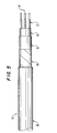
- the improved cable assembly 10 includes; a signal and/or power transmission core 12; a first friction reducing or low friction layer 14; an inner jacket 16; a strength member array 18; and an outer jacket 20.
- layer shall mean a coating covering or wrapping.
- the signal transmission core 12 may be comprised of any suitable elements useful in the transmission of electromagnetic and/or optical signals and /or power.
- the signal transmission core 12 may be comprised of; electrical conductor elements or fiber optic elements for transmitting data and/or providing power to a system (not shown); interstitial fillers for providing radial compressive support; and, if the cable is to be used in a marine environment, a water blocking compound for impeding the flow of gas and fluids into the cable.
- the core 12 is jacketed or coated with the inner jacket 16, which may be comprised of porous polytetrafluoroethylene (PTFE), polyimide, nylon, polyether ether ketone, organopolysiloxane-imide, polyester, polyester terephthalate, full density polytetrafluoroethylene, tetrafluoroethylene-hexafluoropropylene copolymer, perfluoroalkoxy tetrafluoroethylene, ethylene-tetrafluoroethylene copolymer, copolymer of ethylene and PTFE, polyvinyl chloride, rubber, silicone, polyethylene, polyvinylidene fluoride, thermoplastic elastomers, urethane or any other suitable jacket material.
- PTFE porous polytetrafluoroethylene
- polyimide polyimide
- nylon polyether ether ketone
- organopolysiloxane-imide polysiloxane-imide
- polyester polyester terephthal
- the first low friction layer 14 is comprised of materials which exhibit low friction characteristics. Such materials include, but are not limited to, PTFE, polyethylenes, and polyesters,. In a preferred embodiment of the present invention, the first low friction layer 14 is comprised of a porous fluoropolymer material, such as but not limited to porous polytetrafluoroethylene (PTFE) membrane. The first low friction layer 14 is disposed about the signal transmission core 12.
- materials include, but are not limited to, PTFE, polyethylenes, and polyesters,.
- PTFE porous polytetrafluoroethylene
- porous polytetrafluoroethylene shall mean a membrane which may be prepared by any number of known processes, for example, by stretching or drawing processes, by papermaking processes, by processes in which filler materials are incorporated with the PTFE resin and which are subsequently removed to leave a porous structure, or by powder sintering processes.
- the porous polytetrafluoroethylene membrane is porous expanded polytetrafluoroethylene membrane having a microstructure of interconnected nodes and fibrils, as described in U.S. Patent Nos. 3,953,566; 4,187,390; and 4,110,392, which are incorporated herein by reference, and which fully describe the preferred material and processes for making them.
- the porous polytetrafluoroethylene membrane may have a thickness in a range from about 3 to about 1,000 micrometers, preferably in a range of from about 5 to about 100 micrometers, and a pore volume in a range from about 20 to about 98 percent.
- a tape of porous PTFE comprises the first low friction layer 14.
- Application of the tape may be accomplished by radial transfer of the tape to the core 12 at a predetermined lay angle.
- the predetermined lay angle in conjunction with the tape width, provides a desired coverage or overlap which produces minimum wrinkling of the tape, and a predetermined tensioned thickness.
- a suitable lay angle provides a tape overlap equal to, or greater than, 25% of the tape width.
- nominal diameter build up of the tape is about 0.006 inches.
- the tape may be folded longitudinally about the core 12.
- the first low friction layer 14 separates the core 12 from the inner jacket 16 and strength member array 18. Therefore, the low friction layer 14 minimizes mechanical coupling of the inner jacket 16 and strength member array 18 to the core 12, thereby minimizing the transfer of loads from the strength member array 18 to the core 12. Additionally, the low friction layer 14 enhances the flexibility of the cable assembly 10, and reduces elongation of the core 12 when the cable assembly is subjected to cyclic bending and tension.
- the inner jacket 16 is extruded over the first low friction layer 14 and the core 12, which provides a bedding and inner containment for the strength member array 18, and which isolates and protects the core 12.
- the inner jacket 16 also provides a continuous layer which isolates the strength member array 18 from the low friction layer 14, further enhancing the flexibility of the cable assembly 10 and decoupling the strength member array from the core 12.
- the inner jacket 16 is extruded over the core by way of a tube extrusion process, as opposed to a compression extrusion process.
- the tube extrusion process provides an inner jacket construction which is concentric, thin-walled, and substantially smooth.
- the strength member array 18 is comprised of synthetic fibrous strength members 21, which are defined by filaments 22.
- the synthetic strength members 21 are covered, wrapped or enclosed by a second friction reducing layer or low friction layer 24.
- the second low friction layer 24 is comprised of a material which exhibits compressibility characteristics sufficient to enable this low friction layer to flow into the interstitial regions of a strength member 21, thereby providing load distribution and sufficient strength for preventing tearing and breaching of the layer at a point of contact between strength members.
- This second low friction layer 24 also exhibits relatively low friction at the filament interface while providing an interface between layers, where the coated strength members come into contact, sufficient to transfer loads from one strength member to another.
- the second low friction layer 24 may be comprised of a porous fluoropolymer material, such as, but not limited to, a porous PTFE material or a covering or wrapping of porous expanded PTFE membrane. If a covering or wrapping comprising a tape of expanded PTFE membrane is employed as the second low friction layer 24, the tape is wrapped about strength members 21 as described hereinabove for the first low friction layer 14. In such an embodiment, a preferred diameter build up of the tape is about 0.003 inches or less.
- the strength member 21 may comprise fibers, such as but not limited to, fibers of aramid, polyester, polytetrafluoroethylene, polysulfone, or polyamide fibers.
- fibers of aramid such as but not limited to, fibers of aramid, polyester, polytetrafluoroethylene, polysulfone, or polyamide fibers.
- a suitable fibrous strength member is KEVLAR® yarn, a product which is commercially available from E.I. DuPont de Nemours. KEVLAR® is a DuPont trademark for a family of aramid fibers.
- Such a fibrous material may be a short fiber, as well as continuous filament yarn, and has a relatively high tensile strength.
- the properties of this fibrous material are reported in Information Bulletin K-506A revised July, 1986, and entitled, "Properties and Uses of KEVLAR® 29 and KEVLAR® 49 In Electromechanical Cables and Fiber Optics.”
- the number of filaments of the fibrous strength members constitute the denier of the strength member. (Denier is a measure of weight which can also be equated to the geometric size and strength of the member).
- a preferred denier for the fibrous strength members 21 may range within conventional sizes, or configured as required to meet specific needs and performance characteristics.
- a suitable denier ranges from about 200 to about 15,000.
- the strength member array 18 may comprise a plurality of configurations, such as but not limited to a braided configuration (Figure 1), a served or helical configuration (Figure 3), or a dual served or a contra-helical configuration (Figure 4).
- the strength member array may also be disposed within a center region of the core 12 ( Figure 5).
- the coverage of the strength member array 18 should preferably be sufficiently low so as to not overly affect the ability of the outer jacket 20 to bond, through open regions 26 of the strength member array 18, to the inner jacket 16.
- the process may be optimized by employing a strength member array coverage of less than or equal to about 60% (strength member area ⁇ by available area).
- Minimal thickness of the member array may additionally provide for more direct contact between the inner and outer jackets, thereby enhancing bonding there between.
- the strength member array 18 may be additionally coated with a suitable material to enhance bonding or load transfer between the inner and outer jackets and the strength member array.
- Such materials may include, but are not limited to, polyurethane or such other materials which may comprise jackets 16 and 20, and which have been described hereinabove.
- the second low friction layer 24 may be coated with a material of sufficient hardness, higher compressibility and low friction to act as an environmental barrier and to allow for movement of the strength member array.
- a material of sufficient hardness, higher compressibility and low friction may include, but not limited to, polyesters, polypropylenes, and polyethylenes.
- the covered, wrapped or enclosed strength members 21 allow for a broader range of lower braid and serve angles due to the freedom of movement of the filaments.
- the reduction in friction and increased load distribution imparted by the coating increases the flexibility and longevity normally lost due to lower braid and served angles. Twisting the filaments 22 and braiding the construction maximizes load sharing between the filaments and the strength members 21.
- the strength members 21 may be impregnated with a fluoropolymer material prior to being covered, wrapped or enclosed.
- a suitable process for impregnating the strength members 21 is described in detail in U.S. Patent 5,165,993, which is incorporated herein by reference.
- Coating, covering, or wrapping the strength members 21 with a low friction material, such as a porous expanded polytetrafluoroethylene provides a beneficial means for minimizing point loading of the strength members.
- cutting and focused stress caused by overlapping strength members 21, which are inherent in a contra-helical served or braided strength member array 18, is minimized.
- Such a coating, covering, or wrapping reduces the negative effects of point loading, while providing for load sharing between overlapping strength members 21 at the points of contact.
- External coverings like the second low friction layer 24, aid in distributing the loads for impregnated as well as non-impregnated filaments 22 when subjected to compressive loading, hence reducing the tendency for the strength member to "buckle" and "notch".
- the containment and allowed movement of the individual strength members 21 reduces the focused stress caused by compressive loads.
- the resulting reduction in buckling and subsequent notching of the filaments 12 improves the longevity of the strength members 21, when cycled from compression to tension, as is typical of bending and straightening which occurs when the cable is transferred over a sheave during mechanized cable deployment and retrieval.
- Impregnation of the strength member encapsulates each filament 22 of the strength member 21, provides a flexible, low-friction matrix which also distributes loads, allows for movement of the filaments, minimizes stress concentration of overlapping members and additionally impedes the flow of fluids within the cable assembly 10.
- the outer jacket 20 is comprised of a polymeric material which exhibits a molecular affinity with respect to the inner jacket 16. Suitable materials include, but are not limited to, thermoplastic or thermosetting materials.
- the outer jacket 20 is extruded over the strength member array 18 and bonded to the inner jacket 16 by way of a compression extrusion process.
- the outer jacket 20 provides environmental protection for the core 12 and provides load transfer from a cable termination to the strength member array 18.
- the extrusion temperature should be evaluated as necessary to effect the desired bond between the inner and outer jackets, 16, 20.
- a limiting characteristic of such an extrusion process is the potential for a degradation of the extruded resin.
- a reduction in take-up speed of the cable assembly 10, altering coating techniques, and/or increasing a crosshead temperature also may be required to effect the required bond between the inner and outer jackets. Additionally, the thickness of the outer jacket, as well as crosshead pressure, may also be increased to provide the necessary bond between the inner and outer jackets.
- a heating assembly may be employed to preheat the cable assembly 10 prior to the cable assembly entering the extruder to sufficiently prepare the inner jacket 16 for bonding. Pre-drawing and/or pre-heating the core 12 may also be necessary to dry the strength member array 18 in order to prevent out gassing during extrusion period.
- a compression extrusion in contrast to a tube extrusion, is preferred to enhance the filling of the open regions 26 and to enhance bonding of the inner and outer jackets. The filling and compression of the outer jacket material into the open regions 26, utilizing heat and pressure during extrusion, not only is required to effect the required bond, but also is necessary to minimize the voids and air space between the two jackets.
- typical environmental use conditions of the cable assembly 10 may subject the cable assembly to extreme external pressures, which may be caused by such conditions as marine depth. These environmental conditions require void-free cable assembly constructions to maintain and control weight, compression, and to minimize fluid and water migration within the cable assembly construction. Minimizing the air gap interface between the outer jacket 20 and the strength member array 18 enhances the probability of providing a void-free cable assembly construction.
- the bonded inner and outer jacket construction and the strength member array 18, maximize the protection which can be afforded a non-metallic jacket. Additionally, the bonded jacket aids in breaking up the migration of a cut or nick in the jacket.
- This type of cable construction also provides support against forces which otherwise would crush or damage the cable assembly. More particularly, external forces and/or pressure, which might otherwise flatten the cable, are resisted by the mechanical restraint provided by the radial application of the strength member array 18 in conjunction with support provided by the bonded inner and outer jackets.
- This construction as opposed to a metal construction, is non-corrosive, non-magnetic, and provides a higher break strength for an external termination (e.g., a flexible wire mesh type grip) at a smaller size and weight. Additionally this configuration maximizes cut-through protection previously only realized by armor cable constructions.
- the strength member array may be configured within the core of the signal transmission bundle as indicated in Figure 5.
- the array may typically be located in the center and/or interstitial regions of the core and provide load restraint for the cable. Coating the member in the same manner as previously described enhances flexibility, reduces abrasion related degradation, and provides protection required for handling during manufacturing.
- the strength member array 18 may be braided onto the inner jacket 16 as shown in Figure 1, except with coverages in excess of 60%. This design is preferable for applications where the combination of highest flexibility, highest strength, and direct termination to the strength member is desired. Coating the members in the same manner as previously discussed enhances the properties in much the same manner as previously described, with the exception of load transfer through the outer jacket into the strength member array.
- the strength member coating, as described for low coverage braids, provides a barrier between members. This barrier enhances flexibility, reduces load concentration, and minimizes frictional abrasion.
Landscapes
- Insulated Conductors (AREA)
- Ropes Or Cables (AREA)
- Communication Cables (AREA)
Applications Claiming Priority (2)
| Application Number | Priority Date | Filing Date | Title |
|---|---|---|---|
| US08/600,358 US5706382A (en) | 1996-02-13 | 1996-02-13 | Signal transmission assembly having reduced-friction and concentrated load distribution element for synthetic strength members |
| US600358 | 1996-02-13 |
Publications (3)
| Publication Number | Publication Date |
|---|---|
| EP0790624A2 true EP0790624A2 (de) | 1997-08-20 |
| EP0790624A3 EP0790624A3 (de) | 1998-09-09 |
| EP0790624B1 EP0790624B1 (de) | 2002-05-29 |
Family
ID=24403284
Family Applications (1)
| Application Number | Title | Priority Date | Filing Date |
|---|---|---|---|
| EP97300912A Expired - Lifetime EP0790624B1 (de) | 1996-02-13 | 1997-02-13 | Verbesserte Signalübertragungseinheit |
Country Status (5)
| Country | Link |
|---|---|
| US (2) | US5706382A (de) |
| EP (1) | EP0790624B1 (de) |
| JP (1) | JPH09231838A (de) |
| AU (1) | AU1228997A (de) |
| DE (1) | DE69712814T2 (de) |
Cited By (4)
| Publication number | Priority date | Publication date | Assignee | Title |
|---|---|---|---|---|
| EP1460646A1 (de) * | 2003-03-17 | 2004-09-22 | Nexans | Abriebfester Mantel |
| EP1329910A3 (de) * | 2002-01-18 | 2006-07-26 | HEW-KABEL /CDT GmbH & Co. KG | Verfahren zur Herstellung eines Wickelbandes aus ungesintertem Polytetrafluorethylen |
| DE102006025269A1 (de) * | 2006-05-31 | 2007-12-06 | Nexans | Flexible elektrische Leitung |
| WO2012078858A3 (en) * | 2010-12-08 | 2012-08-23 | Thoratec Corporation | Modular driveline |
Families Citing this family (28)
| Publication number | Priority date | Publication date | Assignee | Title |
|---|---|---|---|---|
| US5706382A (en) * | 1996-02-13 | 1998-01-06 | W. L. Gore & Associates, Inc. | Signal transmission assembly having reduced-friction and concentrated load distribution element for synthetic strength members |
| US7346244B2 (en) | 2001-03-23 | 2008-03-18 | Draka Comteq B.V. | Coated central strength member for fiber optic cables with reduced shrinkage |
| US6389204B1 (en) | 2001-05-30 | 2002-05-14 | Corning Cable Systems Llc | Fiber optic cables with strength members and methods of making the same |
| US6553167B2 (en) | 2001-06-04 | 2003-04-22 | Corning Cable Systems Llc | Fiber optic cables having ultra-low shrinking filaments and methods of making the same |
| WO2004040348A1 (en) * | 2002-10-28 | 2004-05-13 | Judd Wire, Inc. | Fiber optic cable demonstrating improved dimensional stability |
| US9334587B2 (en) | 2005-02-11 | 2016-05-10 | W. L. Gore & Associates, Inc. | Fluoropolymer fiber composite bundle |
| US7296394B2 (en) * | 2005-02-11 | 2007-11-20 | Gore Enterprise Holdings, Inc. | Fluoropolymer fiber composite bundle |
| US20060182962A1 (en) * | 2005-02-11 | 2006-08-17 | Bucher Richard A | Fluoropolymer fiber composite bundle |
| US7409815B2 (en) * | 2005-09-02 | 2008-08-12 | Gore Enterprise Holdings, Inc. | Wire rope incorporating fluoropolymer fiber |
| US8689671B2 (en) | 2006-09-29 | 2014-04-08 | Federal-Mogul World Wide, Inc. | Lightweight armor and methods of making |
| US7489844B2 (en) * | 2007-01-08 | 2009-02-10 | Commscope, Inc. Of North Carolina | Ruggedized deep-sea rov deployment cable |
| US7822306B2 (en) * | 2007-01-08 | 2010-10-26 | Commscope, Inc. Of North Carolina | Buoyancy neutral fiber optic cable |
| US7848604B2 (en) * | 2007-08-31 | 2010-12-07 | Tensolite, Llc | Fiber-optic cable and method of manufacture |
| DE202007012165U1 (de) | 2007-08-31 | 2007-11-22 | Nexans | Flexible elektrische Leitung |
| AU2009294243A1 (en) * | 2008-09-19 | 2010-03-25 | Shilat Imaging Ltd | Aerial observation system |
| US7702203B1 (en) | 2008-10-30 | 2010-04-20 | Corning Cable Systems Llc | Armored fiber optic assemblies and methods of making the same |
| US8463095B2 (en) * | 2009-04-09 | 2013-06-11 | Corning Cable Systems Llc | Armored fiber optic assemblies and methods of forming fiber optic assemblies |
| US20100278492A1 (en) | 2009-04-30 | 2010-11-04 | Bohler Gregory B | Armored Fiber Optic Assemblies and Methods of Forming Fiber Optic Assemblies |
| US8331748B2 (en) | 2009-09-30 | 2012-12-11 | Corning Cable Systems Llc | Armored fiber optic assemblies and methods employing bend-resistant multimode fiber |
| US9170390B2 (en) | 2010-04-23 | 2015-10-27 | Corning Cable Systems Llc | Armored fiber optic assemblies and methods of forming fiber optic assemblies |
| US20120073856A1 (en) * | 2010-09-24 | 2012-03-29 | John Mezzalingua Associates, Inc. | Braid configurations in coaxial cables |
| US9052486B2 (en) | 2010-10-21 | 2015-06-09 | Carlisle Interconnect Technologies, Inc. | Fiber optic cable and method of manufacture |
| US9448376B2 (en) * | 2012-05-01 | 2016-09-20 | SeeScan, Inc. | High bandwidth push cables for video pipe inspection systems |
| DE102015213603A1 (de) * | 2015-07-20 | 2017-01-26 | Siemens Aktiengesellschaft | Gasisolierte Leitungsanordnung |
| CN209167604U (zh) * | 2018-06-27 | 2019-07-26 | 罗森伯格技术(昆山)有限公司 | 一种室外铠装光缆 |
| FR3099630A1 (fr) * | 2019-08-02 | 2021-02-05 | Nexans | Cable de puissance equipe d’un dispositif electronique d’identification par radiofrequence |
| CN112497788B (zh) * | 2020-11-11 | 2022-11-22 | 振石集团华智研究院(浙江)有限公司 | 一种碳玻复合frp光缆加强芯及其生产方法 |
| US11619787B1 (en) * | 2021-12-28 | 2023-04-04 | Sterlite Technologies Limited | Embedded strength member for optical fiber cables and manufacturing method thereof |
Family Cites Families (33)
| Publication number | Priority date | Publication date | Assignee | Title |
|---|---|---|---|---|
| US2240769A (en) * | 1937-10-25 | 1941-05-06 | Glazer Max | Means for manufacturing carbonated ice |
| US4082423A (en) * | 1976-08-19 | 1978-04-04 | The United States Of America As Represented By The Secretary Of The Navy | Fiber optics cable strengthening method and means |
| CA1131953A (en) * | 1979-06-01 | 1982-09-21 | Zoltan Zongor | Optical fibre transmission cable reinforcement |
| US4355865A (en) * | 1980-03-21 | 1982-10-26 | Amp Incorporated | Laminated optical fiber cable |
| US4515435A (en) * | 1982-08-10 | 1985-05-07 | Cooper Industries, Inc. | Thermally stabilized fiber optic cable |
| US5230937A (en) * | 1983-04-13 | 1993-07-27 | Chemfab Corporation | Reinforced fluoropolymer composite |
| US4711388A (en) * | 1983-05-24 | 1987-12-08 | Olin Corporation | Process and apparatus for fabricating optical fiber cables |
| US5165993A (en) * | 1983-07-04 | 1992-11-24 | Akzo N.V. | Aromatic polyamide yarn impregnated with lubricating particles, a process for the manufacture of such a yarn, and packing material or rope containing this yarn |
| US4515535A (en) * | 1983-08-15 | 1985-05-07 | Baxter Travenol Laboratories, Inc. | Peristaltic pump quick disconnect rotor assembly |
| US4502364A (en) * | 1983-09-22 | 1985-03-05 | Rm Industrial Products Company, Inc. | Composite fibrous packing material containing fibers of aromatic sulfide polymers |
| US4723831A (en) * | 1985-12-02 | 1988-02-09 | American Telephone And Telegraph Company At&T Bell Laboratories | Optical fiber communications cable |
| US4801764A (en) * | 1986-02-11 | 1989-01-31 | Cooper Industries, Inc. | Cable assembly for use under carpeting |
| DE3636621C2 (de) * | 1986-10-28 | 1995-03-02 | Eilentropp Kg | Hochflexibles elektrisches Kabel oder entsprechende Leitung |
| US5240769A (en) * | 1986-11-25 | 1993-08-31 | Nippon Pillar Packing Co. Ltd. | Packing material and packing made of the same |
| US4818060A (en) * | 1987-03-31 | 1989-04-04 | American Telephone And Telegraph Company, At&T Bell Laboratories | Optical fiber building cables |
| WO1989007778A1 (fr) * | 1988-02-10 | 1989-08-24 | Fujitsu Limited | Cable en fibre optique et production de ce cable |
| FR2633437A1 (fr) * | 1988-06-22 | 1989-12-29 | Cables De Lyon Geoffroy Delore | Cable de soudure avec filet polyurethane |
| US5389442A (en) * | 1988-07-11 | 1995-02-14 | At&T Corp. | Water blocking strength members |
| US5171635A (en) * | 1990-10-10 | 1992-12-15 | E. I. Du Pont De Nemours And Company | Composite wire construction |
| US5201020A (en) * | 1990-11-08 | 1993-04-06 | Corning Incorporated | Reinforced protective tube for optical waveguide fibers |
| US5138684A (en) * | 1991-01-14 | 1992-08-11 | W. L. Gore & Associates, Inc. | High-strength isolated core cable |
| US5148509A (en) * | 1991-03-25 | 1992-09-15 | Corning Incorporated | Composite buffer optical fiber cables |
| US5133034A (en) * | 1991-08-20 | 1992-07-21 | At&T Bell Laboratories | Communications cable having a strength member system disposed between two layers of waterblocking material |
| US5157752A (en) * | 1991-10-24 | 1992-10-20 | Northern Telecom Limited | Optical fiber cable with intermingled water blocking means and method of making same |
| US5399418A (en) * | 1991-12-21 | 1995-03-21 | Erno Raumfahrttechnik Gmbh | Multi-ply textile fabric especially for protection suits and the like |
| US5253318A (en) * | 1992-02-14 | 1993-10-12 | W. L. Gore & Associates, Inc. | Optical fiber ribbon cable |
| US5267338A (en) * | 1992-05-08 | 1993-11-30 | W. L. Gore & Associates, Inc. | Low profile cable having component breakouts and processes for their manufacture |
| US5361806A (en) * | 1992-07-07 | 1994-11-08 | Titeflex Corporation | Kevlar reinforced high pressure hose assembly with grip and environmental barrier |
| CA2120111C (en) * | 1993-04-26 | 2002-06-11 | F. Arthur Simmons | Method of applying adhesive to porous materials |
| US5399428A (en) * | 1994-03-11 | 1995-03-21 | Monsanto Company | Flame retardant polyester copolymers |
| US5557698A (en) * | 1994-08-19 | 1996-09-17 | Belden Wire & Cable Company | Coaxial fiber optical cable |
| US5615293A (en) * | 1996-01-30 | 1997-03-25 | W. L. Gore & Associates, Inc. | Fiber optic cable assembly for facilitating the installation thereof in a structure |
| US5706382A (en) * | 1996-02-13 | 1998-01-06 | W. L. Gore & Associates, Inc. | Signal transmission assembly having reduced-friction and concentrated load distribution element for synthetic strength members |
-
1996
- 1996-02-13 US US08/600,358 patent/US5706382A/en not_active Expired - Lifetime
-
1997
- 1997-01-23 AU AU12289/97A patent/AU1228997A/en not_active Abandoned
- 1997-02-13 JP JP9028886A patent/JPH09231838A/ja active Pending
- 1997-02-13 EP EP97300912A patent/EP0790624B1/de not_active Expired - Lifetime
- 1997-02-13 DE DE69712814T patent/DE69712814T2/de not_active Expired - Lifetime
- 1997-09-22 US US08/935,329 patent/US5920671A/en not_active Expired - Lifetime
Cited By (7)
| Publication number | Priority date | Publication date | Assignee | Title |
|---|---|---|---|---|
| EP1329910A3 (de) * | 2002-01-18 | 2006-07-26 | HEW-KABEL /CDT GmbH & Co. KG | Verfahren zur Herstellung eines Wickelbandes aus ungesintertem Polytetrafluorethylen |
| EP1460646A1 (de) * | 2003-03-17 | 2004-09-22 | Nexans | Abriebfester Mantel |
| US7164078B2 (en) | 2003-03-17 | 2007-01-16 | Nexans | Abrasion-resistant jacket |
| DE102006025269A1 (de) * | 2006-05-31 | 2007-12-06 | Nexans | Flexible elektrische Leitung |
| WO2012078858A3 (en) * | 2010-12-08 | 2012-08-23 | Thoratec Corporation | Modular driveline |
| US8794989B2 (en) | 2010-12-08 | 2014-08-05 | Thoratec Corporation | Modular driveline |
| US9452249B2 (en) | 2010-12-08 | 2016-09-27 | Thoratec Corporation | Modular driveline |
Also Published As
| Publication number | Publication date |
|---|---|
| JPH09231838A (ja) | 1997-09-05 |
| AU1228997A (en) | 1997-08-21 |
| US5920671A (en) | 1999-07-06 |
| US5706382A (en) | 1998-01-06 |
| EP0790624A3 (de) | 1998-09-09 |
| DE69712814T2 (de) | 2003-01-16 |
| EP0790624B1 (de) | 2002-05-29 |
| DE69712814D1 (de) | 2002-07-04 |
Similar Documents
| Publication | Publication Date | Title |
|---|---|---|
| EP0790624B1 (de) | Verbesserte Signalübertragungseinheit | |
| US4675475A (en) | Electrical cable with reinforcement | |
| US4624097A (en) | Rope | |
| US4887422A (en) | Rope with fiber core and method of forming same | |
| AU2008248467B2 (en) | Subsea flexible pipe for transporting oil and gas and including a reinforcing layer | |
| US11646132B2 (en) | Cable with lightweight tensile elements | |
| EP0139166B1 (de) | Optisches Kabel | |
| JPH0564807U (ja) | 光ケーブル素子 | |
| KR20040102000A (ko) | 엘리베이터용 합성섬유로프 | |
| CN1012221B (zh) | 具有非金属铠装系统的光缆 | |
| CN1073546A (zh) | 具有提供阻水和强度特性的缆芯包覆层扎线的通信电缆 | |
| EP1597619A1 (de) | Optisches kabel mit losen hohladern | |
| US20120067020A1 (en) | Composite cable | |
| KR20230154769A (ko) | 섬유 강화 열가소성 복합재 외장을 갖는 동적 케이블 | |
| GB2189071A (en) | Telecommunication cable | |
| PL194212B1 (pl) | Pancerz cięgna Bowdena, cięgno Bowdena oraz sposób wytwarzania pancerza do cięgna Bowdena | |
| GB2105484A (en) | Optical fibre cables | |
| EP0414786A1 (de) | Seelen für drahtseile. | |
| US11578458B2 (en) | Synthetic rope | |
| GB2139779A (en) | Optical fibre cables | |
| GB2179072A (en) | Optical fibre cables | |
| JPS6143683B2 (de) | ||
| KR20230154768A (ko) | 권취 섬유에 의해 강화된 열가소성 외장을 갖는 동적 케이블 | |
| WO1994006126A1 (en) | Miniature electric cable | |
| JPS6222204B2 (de) |
Legal Events
| Date | Code | Title | Description |
|---|---|---|---|
| PUAI | Public reference made under article 153(3) epc to a published international application that has entered the european phase |
Free format text: ORIGINAL CODE: 0009012 |
|
| AK | Designated contracting states |
Kind code of ref document: A2 Designated state(s): DE ES FR GB IT NL SE |
|
| PUAL | Search report despatched |
Free format text: ORIGINAL CODE: 0009013 |
|
| AK | Designated contracting states |
Kind code of ref document: A3 Designated state(s): DE ES FR GB IT NL SE |
|
| 17P | Request for examination filed |
Effective date: 19990302 |
|
| GRAG | Despatch of communication of intention to grant |
Free format text: ORIGINAL CODE: EPIDOS AGRA |
|
| 17Q | First examination report despatched |
Effective date: 20010405 |
|
| GRAG | Despatch of communication of intention to grant |
Free format text: ORIGINAL CODE: EPIDOS AGRA |
|
| GRAH | Despatch of communication of intention to grant a patent |
Free format text: ORIGINAL CODE: EPIDOS IGRA |
|
| GRAH | Despatch of communication of intention to grant a patent |
Free format text: ORIGINAL CODE: EPIDOS IGRA |
|
| GRAA | (expected) grant |
Free format text: ORIGINAL CODE: 0009210 |
|
| AK | Designated contracting states |
Kind code of ref document: B1 Designated state(s): DE ES FR GB IT NL SE |
|
| REG | Reference to a national code |
Ref country code: GB Ref legal event code: FG4D |
|
| REF | Corresponds to: |
Ref document number: 69712814 Country of ref document: DE Date of ref document: 20020704 |
|
| PG25 | Lapsed in a contracting state [announced via postgrant information from national office to epo] |
Ref country code: SE Free format text: LAPSE BECAUSE OF FAILURE TO SUBMIT A TRANSLATION OF THE DESCRIPTION OR TO PAY THE FEE WITHIN THE PRESCRIBED TIME-LIMIT Effective date: 20020829 |
|
| ET | Fr: translation filed | ||
| PG25 | Lapsed in a contracting state [announced via postgrant information from national office to epo] |
Ref country code: ES Free format text: LAPSE BECAUSE OF FAILURE TO SUBMIT A TRANSLATION OF THE DESCRIPTION OR TO PAY THE FEE WITHIN THE PRESCRIBED TIME-LIMIT Effective date: 20021128 |
|
| PLBE | No opposition filed within time limit |
Free format text: ORIGINAL CODE: 0009261 |
|
| STAA | Information on the status of an ep patent application or granted ep patent |
Free format text: STATUS: NO OPPOSITION FILED WITHIN TIME LIMIT |
|
| 26N | No opposition filed |
Effective date: 20030303 |
|
| PG25 | Lapsed in a contracting state [announced via postgrant information from national office to epo] |
Ref country code: IT Free format text: LAPSE BECAUSE OF NON-PAYMENT OF DUE FEES Effective date: 20050213 |
|
| PGFP | Annual fee paid to national office [announced via postgrant information from national office to epo] |
Ref country code: DE Payment date: 20130227 Year of fee payment: 17 Ref country code: FR Payment date: 20130311 Year of fee payment: 17 Ref country code: GB Payment date: 20130227 Year of fee payment: 17 |
|
| PGFP | Annual fee paid to national office [announced via postgrant information from national office to epo] |
Ref country code: NL Payment date: 20130224 Year of fee payment: 17 |
|
| REG | Reference to a national code |
Ref country code: DE Ref legal event code: R119 Ref document number: 69712814 Country of ref document: DE |
|
| REG | Reference to a national code |
Ref country code: NL Ref legal event code: V1 Effective date: 20140901 |
|
| GBPC | Gb: european patent ceased through non-payment of renewal fee |
Effective date: 20140213 |
|
| PG25 | Lapsed in a contracting state [announced via postgrant information from national office to epo] |
Ref country code: NL Free format text: LAPSE BECAUSE OF NON-PAYMENT OF DUE FEES Effective date: 20140901 |
|
| REG | Reference to a national code |
Ref country code: FR Ref legal event code: ST Effective date: 20141031 |
|
| REG | Reference to a national code |
Ref country code: DE Ref legal event code: R119 Ref document number: 69712814 Country of ref document: DE Effective date: 20140902 |
|
| PG25 | Lapsed in a contracting state [announced via postgrant information from national office to epo] |
Ref country code: GB Free format text: LAPSE BECAUSE OF NON-PAYMENT OF DUE FEES Effective date: 20140213 Ref country code: FR Free format text: LAPSE BECAUSE OF NON-PAYMENT OF DUE FEES Effective date: 20140228 Ref country code: DE Free format text: LAPSE BECAUSE OF NON-PAYMENT OF DUE FEES Effective date: 20140902 |