EP0790811B1 - Ausdehnbarer stent gleitglieder verwendend - Google Patents
Ausdehnbarer stent gleitglieder verwendend Download PDFInfo
- Publication number
- EP0790811B1 EP0790811B1 EP95938704A EP95938704A EP0790811B1 EP 0790811 B1 EP0790811 B1 EP 0790811B1 EP 95938704 A EP95938704 A EP 95938704A EP 95938704 A EP95938704 A EP 95938704A EP 0790811 B1 EP0790811 B1 EP 0790811B1
- Authority
- EP
- European Patent Office
- Prior art keywords
- stent
- component
- backbone
- paired
- circumferential
- Prior art date
- Legal status (The legal status is an assumption and is not a legal conclusion. Google has not performed a legal analysis and makes no representation as to the accuracy of the status listed.)
- Expired - Lifetime
Links
Images

Classifications
-
- A—HUMAN NECESSITIES
- A61—MEDICAL OR VETERINARY SCIENCE; HYGIENE
- A61F—FILTERS IMPLANTABLE INTO BLOOD VESSELS; PROSTHESES; DEVICES PROVIDING PATENCY TO, OR PREVENTING COLLAPSING OF, TUBULAR STRUCTURES OF THE BODY, e.g. STENTS; ORTHOPAEDIC, NURSING OR CONTRACEPTIVE DEVICES; FOMENTATION; TREATMENT OR PROTECTION OF EYES OR EARS; BANDAGES, DRESSINGS OR ABSORBENT PADS; FIRST-AID KITS
- A61F2/00—Filters implantable into blood vessels; Prostheses, i.e. artificial substitutes or replacements for parts of the body; Appliances for connecting them with the body; Devices providing patency to, or preventing collapsing of, tubular structures of the body, e.g. stents
- A61F2/82—Devices providing patency to, or preventing collapsing of, tubular structures of the body, e.g. stents
- A61F2/92—Stents in the form of a rolled-up sheet expanding after insertion into the vessel, e.g. with a spiral shape in cross-section
- A61F2/93—Stents in the form of a rolled-up sheet expanding after insertion into the vessel, e.g. with a spiral shape in cross-section circumferentially expandable by using ratcheting locks
-
- A—HUMAN NECESSITIES
- A61—MEDICAL OR VETERINARY SCIENCE; HYGIENE
- A61F—FILTERS IMPLANTABLE INTO BLOOD VESSELS; PROSTHESES; DEVICES PROVIDING PATENCY TO, OR PREVENTING COLLAPSING OF, TUBULAR STRUCTURES OF THE BODY, e.g. STENTS; ORTHOPAEDIC, NURSING OR CONTRACEPTIVE DEVICES; FOMENTATION; TREATMENT OR PROTECTION OF EYES OR EARS; BANDAGES, DRESSINGS OR ABSORBENT PADS; FIRST-AID KITS
- A61F2/00—Filters implantable into blood vessels; Prostheses, i.e. artificial substitutes or replacements for parts of the body; Appliances for connecting them with the body; Devices providing patency to, or preventing collapsing of, tubular structures of the body, e.g. stents
- A61F2/82—Devices providing patency to, or preventing collapsing of, tubular structures of the body, e.g. stents
- A61F2/86—Stents in a form characterised by the wire-like elements; Stents in the form characterised by a net-like or mesh-like structure
- A61F2/90—Stents in a form characterised by the wire-like elements; Stents in the form characterised by a net-like or mesh-like structure characterised by a net-like or mesh-like structure
- A61F2/91—Stents in a form characterised by the wire-like elements; Stents in the form characterised by a net-like or mesh-like structure characterised by a net-like or mesh-like structure made from perforated sheets or tubes, e.g. perforated by laser cuts or etched holes
- A61F2/915—Stents in a form characterised by the wire-like elements; Stents in the form characterised by a net-like or mesh-like structure characterised by a net-like or mesh-like structure made from perforated sheets or tubes, e.g. perforated by laser cuts or etched holes with bands having a meander structure, adjacent bands being connected to each other
- A61F2002/9155—Adjacent bands being connected to each other
- A61F2002/91591—Locking connectors, e.g. using male-female connections
-
- A—HUMAN NECESSITIES
- A61—MEDICAL OR VETERINARY SCIENCE; HYGIENE
- A61F—FILTERS IMPLANTABLE INTO BLOOD VESSELS; PROSTHESES; DEVICES PROVIDING PATENCY TO, OR PREVENTING COLLAPSING OF, TUBULAR STRUCTURES OF THE BODY, e.g. STENTS; ORTHOPAEDIC, NURSING OR CONTRACEPTIVE DEVICES; FOMENTATION; TREATMENT OR PROTECTION OF EYES OR EARS; BANDAGES, DRESSINGS OR ABSORBENT PADS; FIRST-AID KITS
- A61F2250/00—Special features of prostheses classified in groups A61F2/00 - A61F2/26 or A61F2/82 or A61F9/00 or A61F11/00 or subgroups thereof
- A61F2250/0004—Special features of prostheses classified in groups A61F2/00 - A61F2/26 or A61F2/82 or A61F9/00 or A61F11/00 or subgroups thereof adjustable
- A61F2250/001—Special features of prostheses classified in groups A61F2/00 - A61F2/26 or A61F2/82 or A61F9/00 or A61F11/00 or subgroups thereof adjustable for adjusting a diameter
Definitions
- This invention relates to intraluminal stent implants for maintaining support of a body lumen. It comprises an improvement and alternate design to stents which are generally cylindrical in shape and have a plurality of metal elements joined to permit flexing of the stent along the longitudinal axis allowing it to conform to the curves of the inner wall of the targeted lumen.
- metal stents An important use of metal stents is found in situations where part of the vessel wall or stenotic plaque blocks or occludes blood flow in the vessel.
- a balloon catheter is utilized in a percutaneous transluminal coronary angioplasty (PTCA) procedure to enlarge the occluded portion of the vessel.
- PTCA percutaneous transluminal coronary angioplasty
- the dilation of the occlusion can form flaps, fissures and dissections which threaten re-closure of the dilated vessel or even perforations in the vessel wall.
- Implantation of stents can provide support for such problems and prevent reclosure of the vessel or provide patch repair for a perforated vessel.
- the stent overcomes the natural tenancy of the vessel walls of some patients to collapse, thereby maintaining a more normal flow of blood through that vessel than would be possible if the slant were not in place.
- Another type of metal stent involves a tube of stainless wire braid.
- the tube is positioned along a delivery device, such as a catheter, in extended form, making the tube diameter as small as possible.
- a delivery device such as a catheter
- the stent When the stent is positioned across the lesion, it is expanded, causing the length of the tube to contract and the diameter to expand.
- the tube Depending on the materials used in construction of the stent, the tube maintains the new shape either through mechanical force or otherwise. The alteration in the length is undesirable due to the deformation of the stent, the longitudinal abrasion on the inner wall and the unpredictable coverage when fully in place.
- An additional form of metal stent is a heat expandable device using Nitinol or a tin-coated, heat expandable coil.
- the stent is delivered to the affected area on a catheter capable of receiving heated fluids. Once properly situated, heated saline is passed through the portion of the catheter on which the stent is located, causing the stent to expand. Numerous difficulties have been encountered with this device, including difficulty in obtaining reliable expansion, and difficulties in maintaining the stent in its expanded state.
- a popular metal stent is the Palmaz stent. It involves a stainless steel cylinder having a number of slits in its circumference, resulting in a mesh when expanded. The stainless steel cylinder is delivered to the affected area by means of a balloon catheter, and is then expanded to the proper size.
- Stents can be deployed in a body lumen by means appropriate to their design.
- One such method would be to fit the collapsed stent over an inflatable element of a balloon catheter and expand the balloon to force the stent into contact with the body lumen.
- the problem material in the vessel is compressed in a direction generally perpendicular to the wall of the vessel which, consequently, dilates the vessel to facilitate blood flow therethrough.
- Radial expansion of the coronary artery occurs in several different dimensions and is related to the nature of the plaque. Soft, fatty plaque deposits are flattened by the balloon and hardened deposits are cracked and split to enlarge the lumen. It is desirable to have the stent radially expand in an uniform manner.
- the stent may be mounted onto a catheter which holds the stent as it is delivered through the body lumen and then releases the stent and allows it to expand into contact with the body lumen. This deployment is effected after the stent has been introduced percutaneously, transported transluminally and positioned at a desired location by means of the catheter.
- a stent that has sufficient structural integrity to be placed within a vessel at the site of a stenotic lesion, or the like, to support the vessel wall against collapse and yet is flexible and compliant enough for safe and effective delivery to the site of an obstruction. It would also be desirable to provide a stent which is soft and compliant enough to avoid arterial rupture or aneurysm formation at the ends of the stent even when exposed to continuous stresses from the beating heart during chronic implantation.
- an effective stent that maintains an open vessel, is easily delivered to the affected area, one that is easily expanded to a desired size, and maintains that size, easily conforms to the shape of the effected vessel, and is easily used in multiples to treat curved vessels and varying lengths of lesions.
- the stent should not alter in length during expansion or incorporate plastic deformation during such uniform expansion.
- EP-A-0 621 017 stents are disclosed which comprise a cylindrical sheet having overlapping edges comprising a series of protrusions and apertures that interlock and ratchet as the stent expands to an open position.
- a specific embodiment is disclosed, employing a plurality of strips or stent rings which are formed from one sheet of material, with the stent rings having teeth along their edges.
- the stent rings are formed by passing the ends through appropriate slots, whereupon the stent is formed into a cylindrical shape.having a plurality of stent rings joined at a tab portion.
- this prior art stent is formed from one sheet of material.
- the present invention provides a lumen support device, or a stent, used to open or expand a body lumen.
- the stent incorporates elongated parallel stent components with circumferential members, fingers, which weave into paired slots of an adjacent stent component.
- the stent incorporates these sliding elements, that is these projections or fingers, such that they slide through paired slots in a weave-like interlocking configuration enabling the stent to expand radially without yielding or plastically deforming the material of which the stent is fabricated.
- a series of paired slots allow for the insertion of a series of the fingers.
- the fingers may utilize an arresting mechanism giving a controlled expansion with little or no recoil or collapse.
- the slots also allow for uniform, smooth expansion without change in longitudinal dimensions of the complete assembly.
- the plurality of parallel elongated stent components form a cylindrical configuration.
- the assembly is compressed radially by fully sliding the fingers through the slots.
- the assembly is expanded with either the help of a balloon catheter, by the material's elastic response, or both.
- a stent formed in accordance with the present invention is expandable from a reduced diameter configuration, which facilitates delivery to the site of a targeted obstruction, to an expanded configuration when disposed within the targeted area of the vessel.
- the device is delivered using a percutaneous transluminal catheter device which may or may not incorporate an inflatable balloon used to expand the stent.
- the stent Delivered to the locus of a lesion in its reduced diameter configuration on the distal end of an expandable catheter, the stent can be expanded in vivo to its supporting diameter by expanding the expandable portion of its associated catheter.
- the expansion may be accomplished through a balloon catheter or by using self-expanding material, the weave-like fingers being withdrawn through the paired slot to an arrested position. Any plaque or the like can be compressed at the time of stent placement.
- the features of this invention make it possible to provide a stent able to support body lumens and conform to curves or irregularities in body lumens without losing its formation or its longitudinal dimensions.
- Yet another object of the present invention is to provide a stent which can be selectively sized in accordance with the anatomic configuration dictated by the lesion.
- the present invention relates to a radially expandable stent used to open or expand a targeted area in a body lumen.
- the stent has a generally hollow cylindrical shape with open distal and proximal ends as demonstrated in Figs 1 and 7.
- the cylindrical body comprises a plurality of elongated stent components which are interconnected by means of an interlocking weave-like mechanism.
- the device is delivered using a percutaneous transluminal catheter device which may or may not incorporate an inflatable balloon used to expand the stent.
- the stent is designed to permit flexing both radially and longitudinally to conform to the curved body of the applicable lumen.
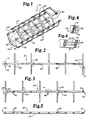
- Fig. 1 illustrates one preferred design of the present invention, referred to as the first stent embodiment.
- the stent generally designated in Fig. 1, incorporates circumferential members or fingers 20 positioned along elongated stent components, generally designated 21, 22, and 23 (also seen in Figs. 2, 3, & 5). Upon assembly of these components fingers 20 weave into paired slots 30 positioned along adjacent stent components 21,22 and 23 as shown in Fig. 1.
- This interlocking system is continued using additional parallel stent components in which the last component is weaved into the first component to form a open ended hollow cylinder construction of appropriate desired diameter as shown in Fig. 1.
- This continuous interlocking weave-like network radially expands while positioned in the lumen through the use of a balloon to a determined diameter or by use of self-expanding material.
- the first stent component 21 shown in Fig. 2 of the first stent embodiment has a longitudinal backbone 31 with a plurality of pairs of opposing circumferential members 20 or fingers extending perpendicular from the backbone 31. Paired slots 30 are positioned along the backbone 31 alternating in position with the circumferential members 20. The paired slots 30 as shown in Figs 4 and 6 are parallel to each other and are linear relative to the backbone 31 of the stent component.
- the backbone of stent component 21 has a proximal end 50 and a distal end 70.
- the paired slots 30 and the circumferential members 20 alternate along the backbone 31 starting with a paired slot 30 at the proximal end 50 and concludes with a pair of circumferential members 20 at the distal end 70.
- the second stent component, generally designated 22, shown in Fig 3 is similar in construction to that of stent component 21 except for the order in which the plurality of circumferential members 20 and paired slots 30 are alternately positioned.
- stent component 22 the order starts with a pair of circumferential members 20 at the proximal end 50 of backbone member 32 and terminates with a pair of slots 30 at the distal end 70 of stent component 22.
- the third stent component generally designated 23, illustrated in Fig. 5, also incorporates an elongated backbone 33 with a plurality of paired slots 30 positioned equidistantly along the entire length of the backbone 33. In this particular stent component there are no circumferential members positioned along the backbone.
- these three stent components 21, 22 and 23 incorporate sliding elements to create a cylindrical configuration as shown in Fig. 1.
- the weaving or interlocking mechanism is achieved by sliding the circumferential members, or fingers 20, of one component through the paired slots 30 of another stent component adjacent to the former in a weave configuration, generally designated as 82 illustrated in Fig. 14. This mechanism enables the stent to expand radially without yielding or plastically deforming the material of which the stent is fabricated. The resulting expanded configuration is best seen in Fig. 1.
- stent component 21 is positioned adjacent and parallel to stent component 22 and is connected thereto by way of the interconnecting weave-like mechanism 82 formed of elements 20 and 30.
- Stent component 22 is positioned adjacent and parallel to stent component 23 and connected thereto by means of the interconnecting weave-like 82 mechanism of fingers 20 and slots 30.
- the opposing circumferential members 20 of stent component 21 are weaved into the paired slots 30 of the stent component 23.
- Stent components 21, 22 & 23 form a series of stent components.
- another series of the three components may be added in the same manner as the first series has been connected.
- Fig. 1 illustrates the use of two series of components closed to create the cylindrical shape.
- Stent component 23 of the final series added would be connected to stent component 21 of the first series to complete the cylindrical stent configuration, this is referred to as "closing" the stent to create the cylindrical shape from the individual parts.
- the potential diameter of the stent may also be increased by extending the length of the fingers.
- the paired slots 30 dimensions are such that the fingers 20 is held via friction tension or clamping giving a controlled expansion with little or no recoil or collapse.
- the slot arrangement incorporates multiple parallel paired slots 30 so that the fingers can weave through them providing more control over the sliding movement as shown in Fig. 14.
- the center portion 29 that lies between the paired slots 30, as illustrated in Figs 4 and 6, may be raised or lowered with respect to the plane of the stent component 21, 22 and 23 as shown in Fig. 1. As the center piece 29 between paired slots 30 is raised or lowered, the friction tension diminishes, loosening the weave-like connection 82 and thus allowing the fingers 20 to slide more freely through the paired slots 30.
- the center piece 29 may be raised or lowered to the extent that the friction tension between the finger 20 and the paired slot 30 is lose enough so as to allow the balloon or expanding means to expand the stent, but tight enough so as to prevent the finger 20 from withdrawing as a result of the stent's own expanding force or to prevent the stent from collapsing under the pressure of the lumen wall.
- the assembly forms the cylindrical hollow configuration as seen in Fig. 1 and it can be compressed radially by fully sliding the fingers 20 through the slots 30 for easy insertion into the lumen.
- the assembly is expanded with either the help of a balloon catheter, by the elastic response of the material used, or both, the weave mechanism 82 allowing for radial expansion without change in longitudinal dimensions of the complete assembly.
- This application of the weave-like mechanism utilizes at least two dissimilar elongated stent components generally designated 40 and 42, shown in Fig's 8 & 9, respectively, and like the first stent embodiment of Fig. 1 can be expanded to larger diameters by adding additional series of the two components.
- the two dissimilar stent components 40 and 42 which form a continuous interlocking weave-like network, eventually close to form an open ended cylindrical configuration from the individual components 40 and 42 as shown in Fig. 7.
- To achieve this closing the fingers 69 of component 42 of the last series used in the construction are inserted into the paired slots 43 of stent component 40 of the first series used in the construction.
- This particular embodiment radially expands while positioned in the lumen through the use of a balloon to a determined diameter or by use of a self-expanding material.
- Fig 7 demonstrates the use of two series of components in a continuous radially expandable weave-like cylinder construction.
- Stent component 40 shown in Fig. 8 has an elongated zig-zag backbone 44 having a set of first edge members 45 linearly arranged and a set of second edge members 46 linearly arranged, the set of first edge members 45 and the set of second edge members 46 being parallel and positioned on opposite sides of the zig-zag backbone 44.
- a plurality of circumferential members, 41 or fingers extend perpendicular from the first edge members 45 of the zig-zag backbone 44.
- a plurality of paired slots 43 are positioned along the set of second edge members 46 of the zig-zag backbone 44.
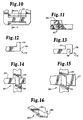
- the paired slots 43 as shown in Fig. 10 are parallel to each other and are linear relative to the backbone 44.
- the backbone of stent component 40 has a proximal end 50 and a distal end 70.
- the second edge members 46 and the first edge members 45 alternate along the backbone starting with edge member 46a at the proximal end 50 and ends with a first edge member 45a at the distal end 70.
- Stent component 42 shown in Fig 9 has an elongated zig-zag backbone 47 having a set of first edge members 60 linearly arranged and a set of second edge members 61 linearly arranged, the set of first edge members and the set of second edge members being parallel and positioned on opposite sides of the zig-zag backbone 47.
- a plurality of circumferential members 69 or fingers extend inwardly and perpendicular from the second edge members 61 of the zig-zag backbone 47.
- a plurality of paired slots 43 are positioned along the set of first edge members 60 of the zig-zag backbone 47.
- the paired slots as shown in Fig. 10 are parallel to each other and are linear relative to the backbone of the stent component 42.
- the backbone of the stent component 42 has a proximal end 50 and a distal end 70.
- the first edge members 60 and the second edge members 61 alternate along the backbone starting with a second edge member 61a at the proximal end 50 and concludes with a first edge member 60a at the distal end 70.
- these two stent components 40 and 42 incorporate sliding elements 41 and 69 to form a cylindrical configuration as shown in Fig. 7, incorporating at least two of the elongated stent components.
- the circumferential members or fingers 41 or 69 of one component slide through the paired slots 43 of an adjacent stent component in a weave-like configuration as shown in Fig. 7 enabling the stent to expand radially without yielding or plastically deforming the material of which the stent is fabricated.
- Stent component 40 is positioned adjacent to the second stent component 42 and connected to component 42 by way of the interconnecting weave-like mechanism of combined slots 43 of stent component 42 and fingers 41.
- Fig. 7 illustrates the use of two series of stent components 40 and 42.
- the stent component 42 of the final series is connected to stent component 40 of the first series thus creating the cylindrical stent formation shown in Fig. 7. This connection is achieved through the weave-like mechanism discussed earlier illustrated in Fig. 14.
- the circumferential members or fingers 20, 41 and 69 and the center pieces 29 may be modified to incorporate arresting mechanisms which prevent the disengagement of the fingers from the paired slots 30 and 43 upon expansion, and also may serve to prevent collapse when the friction tension is inadequate.
- arresting mechanisms In the absence of, or in conjunction with, arresting mechanisms, the fingers are held in place by friction tension by way of the weave-like connection as shown in Fig. 14.
- the paired slots 30 and 43 dimensions of the first stent embodiment and the second stent embodiment, respectively, are such that the fingers can be held via friction tension or clamping giving a controlled expansion with little or no recoil or collapse.
- the center portion 29 that lies between the paired slots 30 and 43, respectively, as illustrated in Figs 6 and 10, may be raised or lowered with respect to the plane of the stent components as illustrated in Figs. 1, 7 and 11. As the center piece 29 is raised or lowered, the friction tension diminishes, loosening the weave-like connection and thus allowing the fingers 20, 41 and 69 to slide more freely through the coordinating paired slots 30 and 43.
- the center piece 29 is raised or lowered to the extent that the friction tension between the fingers and the paired slots is lose enough so as to allow the balloon or expanding means to expand the stent, but tight enough so as to prevent the finger from withdrawing as a result of the stent's own expanding force or to prevent the stent from collapsing under the pressure of the lumen wall.
- This arresting mechanism may be a simple lip arresting mechanism, generally designated 72, as shown in Fig. 12, wherein a lip 73 is positioned at the end 74 of the fingers 20, 41 or 69.
- the modified finger which incorporates the simple lip 73, is slid through the corresponding paired slot 30 and 43 allowing the lip to engage the paired slot preventing removal.
- the fingers may incorporate multiple lip structures along the finger to act as a ratcheting mechanism allowing for greater freedom in setting the potential diameter and as a prevention from collapse of the stent body under the pressure of the vessel.
- a lip and catch arresting mechanism generally designated 75, as shown in Fig. 13, may also be used.
- the modified finger 20 & 41 incorporates a lip 77 and catch 78 at the end 76 of the circumferential member as demonstrated in Fig. 13.
- the lip 77 and catch 78 arrangement allows for the engagement and locking of the paired slots 30 or 43 restricting movement in either direction.
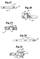
- FIG. 17 Another potential arresting mechanism could be a dimple or detent arresting mechanism, the elements of which are illustrated in Figs. 17, 18 & 19.
- This arresting mechanism incorporates a male portion, which is a modified circumferential member end, generally designated 90, as shown in Fig. 17, with a raised convex portion 94 positioned toward the end 96 of a circumferential member as shown in Fig. 17.
- the female portion for the second stent embodiment, generally designated 100, as shown in Fig. 18, is a modified center piece 29 between a paired slot 43.
- the modified center piece 29 has a dimple 102 or detent positioned on the underside of the center piece 29 between the paired slots 43.
- the male portion 94 and the female portion 102 form a mating relationship as the finger is withdrawn from the paired slots 43, securing the finger in the corresponding paired slot.
- the first stent embodiment may also use this dimple or detent arresting mechanism.
- the first stent embodiment uses the modified circumferential member 90 as shown in Fig. 17 for its male portion and a modified center piece 29 between paired slots 30, generally designated 110, as shown in Fig. 19, for its female portion.
- the modified center piece 29 is raised or lowered slightly and has a dimple 102 or detent positioned on the underside of the center piece 29 between the paired slots 30, as shown in Fig. 19.
- the male portion 94 and the female portion 102 form a mating relationship as the finger is withdrawn from the paired slots 30, securing the finger in the corresponding paired slot.
- the male portion and the female portion may be switched, positioning the male portion on the center pieces 29 and positioning the female portions on the circumferential members.
- the modified finger shown in Fig. 17 may also be utilized alone as an arresting mechanism.
- the finger is pushed through the receiving paired slot until the convex portion 94 is exposed on the other side, locking the finger in place.
- This mechanism prevents the finger from being pulled out, but it depends on friction tension to prevent collapsing of the stent body.
- Figs. 20 and 21 illustrate an arresting mechanism that prevents withdrawal of the finger end 96 as well as collapse of the stent.
- Multiple convex portions 94 may by positioned along the finger creating a rachet mechanism within the paired slot as shown in Fig. 21. This ratcheting mechanism allows for greater freedom in setting the potential diameter, and as a prevention from collapse of the stent body under the pressure of the vessel.
- Fig. 15 shows still further means by which to arrest the finger in place in the corresponding paired slot.
- This tapered end arresting mechanism generally designated 84, as shown in Fig. 15, demonstrates an arresting mechanism in which the end of the circumferential member 20, 41 or 69 increasingly widens 27, creating more resistance within the paired slots 30 or 43 as the finger is withdrawn, eventually stopping the finger in a secure position by wedging 28 it into the pair slot, not allowing further expansion.
- Still another arresting mechanism is the arrowhead arresting mechanism, generally designated 80, as shown in Fig. 16.
- This mechanism incorporates an arrowhead 86, which allows the finger 20, 41 or 69 to slide into the paired slot 30 or 43, but prevents the finger from being withdrawn past a certain point because of the barbs 83 on the arrowhead.
- the fingers may incorporate multiple arrowhead structures along the finger to act as a ratcheting mechanism allowing for greater freedom in setting the potential diameter and as a prevention from collapse of the stent body under the pressure of the vessel.
- arresting mechanisms can be incorporated anywhere along the length of the finger to let the stent radially expand to a predetermined diameter without allowing the fingers to fully slide out of the corresponding slots.
- Arresting mechanisms can be positioned to prevent both further expansion and the collapse of the stent.
- the weave-like interconnecting mechanism and arresting mechanism in the second embodiment shown in Fig. 7 is accomplished in the same manner as the first embodiment illustrated by Fig. 1, but the configuration of stent component 42 of the second stent embodiment of Fig. 7 will be such that the finger length 69 will be longer than that of the finger 41 length of the stent component 40 and will only incorporate an arresting mechanisms as shown in Figs 12, 13, 15, and 16 at the end of the circumferential member 69. Finger 69 incorporates friction tension to secure it in any place along the length of the circumferential member as shown in Fig. 7. This extra length allows for more flexibility within the lumen, expanding to engage the walls of the lumen uniformly along the entire length of the stent.
- the finger 69 of component 42 is allowed to slide freely through the corresponding paired slot 43 of stent component 40 allowing the stent to expand uniformly through the use of a catheter balloon or self-expanding material.
- the extra long finger 69 of stent component 42 prevents the weave-like connection 82 from releasing during expansion without limiting the potential diameter. This will ensure that the stent will not have a too small a diameter for the lumen and that future expansion may take place via re-dilatation by a balloon.
- the parts for the components for both embodiments may be fabricated from a metal as well as other materials.
- Indicated metals are Elgiloy alloy, stainless steel, nitinol alloy and biodegradable and nonbiodegradable plastic.
- a possible parts fabrication method would be to use a photo-etching process. In this process a mask is developed such that when the sheet of material is etched in a reacting solution, such as acid, the masked or protected portions form the stent components.
- the photo-etching process allows for an accurate fabrication technique and selective etching optimizing part thickness and size. This technique allows for selective half-etching of the slot webs to facilitate finger assembly.
- An improvement of the present invention over the prior art is the advantages of the sliding mechanism that allows for uniform stent expansion and the design of the stent components allowing for conforming flexibility.
- the sliding mechanisms facilitates stent expansion without incorporating plastic deformation.
- the present stent invention keeps a constant cylindrical shape during radial expansion without altering the shape of the stent elements.
- the longitudinal size of the stent also remains constant as it expands within the lumen. Whereas previously created stents in the prior art have a tendency to lose their longitudinal or cylindrical shape during radial expansion, the present invention remains consistent in its general configuration both in length and in cylindrical uniformity.
- the design of the present invention enables the stent to conform to the walls of the lumen without any increase in length or incorporation of plastic deformation while maintaining structural integrity.
- a further advantage of the present invention over the prior art is its frame-like construction. This construction allows for adequate support while using minimal material. This is an advantage over the rolled tube-like stent illustrated by the Stack patent, U.S. patent 5,306,286. It is preferable to have no more than 10-15% of the inner wall covered by the stent itself. The smaller surface area that contacts the inner lumen wall of the present invention allows for greater exposure to blood and other substances essential to the viability of the inner wall of the lumen without losing support.
- the zig-zag construction of the second embodiment solves the rigidity problem common among many pieces of prior art.
- This construction allows the stent more longitudinal flexibility to conform to irregularities in the lumen.
- Stents such as the Stack stent, 5,306,286, are constructed using a one piece material rolled over upon itself. This one piece formation limits its longitudinal flexibility causing it to be more stiff and nonconforming to the inner walls of the targeted lumen.
Landscapes
- Health & Medical Sciences (AREA)
- Engineering & Computer Science (AREA)
- Biomedical Technology (AREA)
- Cardiology (AREA)
- Oral & Maxillofacial Surgery (AREA)
- Transplantation (AREA)
- Heart & Thoracic Surgery (AREA)
- Vascular Medicine (AREA)
- Life Sciences & Earth Sciences (AREA)
- Animal Behavior & Ethology (AREA)
- General Health & Medical Sciences (AREA)
- Public Health (AREA)
- Veterinary Medicine (AREA)
- Media Introduction/Drainage Providing Device (AREA)
- Materials For Medical Uses (AREA)
- Prostheses (AREA)
Claims (25)
- Ein radial expandierbarer Stent für die Implantierung in ein Körperlumen, umfassend:wobei der Stent radial expandierbar ist, um in die Lumen-Wände einzugreifen durch Verschieben der umlaufenden Elemente (20, 41, 69) durch die paarweisen Schlitze (30, 43) zum Trennen der Bestandteile in diametraler Richtung voneinander.eine Vielzahl von gestreckten Stent-Bestandteilen (21, 22, 23, 40, 42), wobei die Stent-Bestandteile längs und im wesentlichen parallel zueinander angeordnet sind;eine Vielzahl von umlaufenden (circumferential) Elementen (20, 41, 69), im wesentlichen senkrecht befestigt an den Stent-Bestandteilen (21, 22, 23, 40, 42); undeine Vielzahl von paarweisen Schlitzen (30, 43), positioniert entlang der Stent-Bestandteile, wobei die paarweisen Schlitze parallel relativ zu den gestreckten Stent-Bestandteilen (21, 22, 23, 40, 42) liegen, und wobei die umlaufenden Elemente (20, 41, 69) eines Bestandteiles verschiebbar in den paarweisen Schlitzen eines benachbarten Bestandteils aufgenommen werden, und dabei eine webartige Verschlusskonfiguration (82) (weave-like interlocking configuration) ausbilden, und wobei der radial expandierbare Stent einen im allgemeinen zylindrischen Körper mit offenen proximalen und distalen Enden aufweist;
- Stent nach Anspruch 1, wobei die Vielzahl von gestreckten Stent-Bestandteilen umfasst:einen ersten Stent-Bestandteil (21) mit einer Längsstruktur (31), die ein proximales Ende (50) und ein distales Ende (70) aufweist;eine Vielzahl von einander paarweise gegenüber liegenden umlaufenden Elementen (20), die rechtwinklig an dem ersten Stent-Bestandteil befestigt und daran entlang beabstandet sind;eine Vielzahl von paarweisen Schlitzen (30), die linear und voneinander beabstandet entlang der Längsstruktur (31) des ersten Stent-Bestandteils (21) positioniert sind, wobei die paarweisen Schlitze und die umlaufenden Elemente (20) in ihrer Position zueinander alternieren, beginnend mit einem paarweisen Schlitz (30) am proximalen Ende des ersten Stent-Bestandteils;einen zweiten Stent-Bestandteil (22), mit einer Längsstruktur (32), die ein proximales Ende (50) und ein distales Ende (70) aufweist;eine Vielzahl von einander paarweise gegenüber liegenden umlaufenden Elementen (20), die rechtwinklig an dem zweiten Stent-Bestandteil befestigt und daran entlang beabstandet sind;eine Vielzahl von paarweisen Schlitzen (30), die linear und voneinander beabstandet entlang der Längsstruktur (32) des zweiten Stent-Bestandteils (22) positioniert sind, wobei die paarweisen Schlitze und die umlaufenden Elemente (20) in ihrer Position zueinander alternieren, beginnend mit einem Paar der umlaufenden Elemente (20) am proximalen Ende (50) des zweiten Stent-Bestandteils (22); undein dritter Stent-Bestandteil (23), umfassend eine Längsstruktur (33), mit paarweisen Schlitzen, die linear entlang der Längsstruktur (33) positioniert sind.
- Stent nach Anspruch 1, wobei der potentielle Durchmesser des Stents durch Hinzufügen zusätzlicher Reihen von Bestandteilen (21, 22, 23) vergrößert wird, wobei eine Reihe den ersten Stent-Bestandteil (21), den zweiten Stent-Bestandteil (22) und den dritten Stent-Bestandteil (23) umfasst.
- Stent nach Anspruch 3, wobei die paarweisen Schlitze (30) zwei parallele Schlitze umfassen, die linear entlang der Struktur (31, 32, 33) der Stent-Bestandteile (21, 22, 23) angeordnet sind.
- Stent nach Anspruch 4, ferner umfassend einen Arretiermechanismus, der ein Lösen der umlaufenden Elemente (20) aus jedem entsprechenden paarweisen Schlitz (30) verhindert.
- Stent nach Anspruch 5, wobei der Stent aus einem Material gemacht ist, welches aus der Gruppe bestehend aus Elgiloy-Legierung, rostfreiem Stahl, biologisch abbaubarem Kunststoff, nicht-biologisch abbaubaren Kunststoff sowie Nitinol-Legierung ausgewählt ist.
- Stent nach Anspruch 6, wobei der Arretiermechanismus eine Lippe (lip) (73) am Ende (74) mindestens eines der umlaufenden Elemente (20) umfasst, welche in den entsprechenden paarweisen Schlitz (30) eingreift, wenn der Stent expandiert wird.
- Stent nach Anspruch 6, wobei der Arretiermechanismus einen erhabenen Teil auf mindestens einem umlaufenden Element (20) aufweist, welches in den entsprechenden paarweisen Schlitz (30) eingreift, wenn der Stent expandiert wird.
- Stent nach Anspruch 8, wobei das umlaufende Element (20) eine Vielzahl von erhabenen Teilen umfasst.
- Stent nach Anspruch 6, wobei der Arretiermechanismus eine Sperrklinkenanordnung (lip and catch arrangement) (75) umfasst, welche in den entsprechenden paarweisen Schlitze (30) eingreift und eine Bewegung in beliebige Richtung beschränkt, wenn der Stent expandiert wird.
- Stent nach Anspruch 6, wobei der Arretiermechanismus ein Pfeilspitzenelement (arrowhead element) (80, 86) umfasst, das an mindestens einem umlaufenden Element (20) eingebaut ist, und das in den entsprechenden paarweisen Schlitz (30) eingreift, wenn der Stent expandiert wird.
- Stent nach Anspruch 11, wobei das umlaufende Element (20) eine Vielzahl von Pfeilspitzenelementen (80, 86) umfasst.
- Stent nach Anspruch 6, wobei der Arretiermechanismus ein Element von ansteigender Breite (27) in Richtung des distalen Endes des umlaufenden Elements (20) umfasst, welches in einem entsprechenden paarweisen Schlitz (30) eingreift, wenn der Stent expandiert wird.
- Stent nach Anspruch 1, wobei die Vielzahl von gestreckten Stent-Bestandteilen umfasst:einen ersten Stent-Bestandteil (40) mit einer Zick-Zack-Längsstruktur (44), die einen Satz von ersten Kantengliedern (45) aufweist, die linear angeordnet sind, und einen Satz von zweiten Kantengliedern (46), die linear angeordnet sind, wobei die ersten Kantenglieder und die zweiten Kantenglieder parallel zueinander und auf entgegengesetzten Seiten der Zick-Zack-Struktur positioniert sind;eine Vielzahl von umlaufenden Elementen (41), die sich rechtwinklig und auswärts von den ersten Kantengliedern (45) der Zick-Zack-Struktur (44) des ersten Stent-Bestandteils (40) erstrecken;eine Vielzahl von paarweisen Schlitzen (43), positioniert in den zweiten Kantengliedern (46) der Zick-Zack-Struktur (44) des ersten Stent-Bestandteils (40), wobei die paarweisen Schlitze parallel zueinander und linear bezüglich der Längsstruktur des ersten Stent-Bestandteils angeordnet sind, und die Längsstruktur des ersten Stent-Bestandteils ein proximales Ende (50) und ein distales Ende (70) aufweist;
wobei die ersten Kantenglieder (45) und die zweiten Kantenglieder (46) in ihrer Position entlang der Längsstruktur (44) des ersten Stent-Bestandteils (40) alternieren, beginnend mit einem zweiten Kantenglied (46a) am proximalen Ende;einen zweiten Stent-Bestandteil (42) mit einer Zick-Zack-Längsstruktur (47) mit einem Satz von ersten Kantengliedern (60), die linear angeordnet sind, sowie einem Satz von zweiten Kantengliedern (61), die linear angeordnet sind, wobei die ersten Kantenglieder und die zweiten Kantenglieder parallel und auf gegenüber liegenden Seiten der Zick-Zack-Längsstruktur positioniert sind;eine Vielzahl von umlaufenden Elementen (69), die sich senkrecht und einwärts von den ersten Kantengliedern (60) der Zick-Zack-Längsstruktur (47) des zweiten Stent-Bestandteils (42) erstrecken;eine Vielzahl von paarweisen Schlitzen (43), die in den zweiten Kantengliedern (61) der Zick-Zack-Längsstruktur (47) des zweiten Stent-Bestandteils (42) positioniert sind, wobei die paarweisen Schlitze parallel zueinander und linear bezüglich der Längsstruktur des zweiten Stent-Bestandteils angeordnet sind, und die Längsstruktur des zweiten Stent-Bestandteils ein proximales Ende (50) und ein distales Ende (70) aufweist, wobei die ersten Kantenglieder (60) und zweiten Kantenglieder (61) in ihrer Position entlang der Längsstruktur (47) des zweiten Stent-Bestandteils (42) alternieren, beginnend mit einem ersten Kantenglied (61a) am proximalen Ende; wobei die umlaufenden Elemente (41) des ersten Stent-Bestandteils (40) in die paarweisen Schlitze (43) des zweiten Stent-Bestandteils (42) verschiebbar aufnehmbar sind, und die umlaufenden Elemente (69) des zweiten Bestandteils (42) in die entsprechenden paarweise Schlitze (43) des ersten Stent-Bestandteils (40) verschiebbar aufnehmbar sind. - Stent nach Anspruch 14, wobei der potentielle Durchmesser des Stents durch Hinzufügen einer zusätzlichen Reihe von Stent-Bestandteilen (40, 42) vergrößert wird, wobei eine Reihe den ersten Stent-Bestandteil (40) und den zweiten Stent-Bestandteil (42) umfasst.
- Stent nach Anspruch 15, wobei die paarweisen Schlitze (43) zwei parallele Schlitze umfassen, die linear entlang der Längsstruktur der Stent-Bestandteile positioniert sind.
- Stent nach Anspruch 16, ferner umfassend einen Arretiermechanismus, der das Lösen der umlaufenden Elemente (41) des ersten Stent-Bestandteils (40) aus jedem entsprechenden paarweisen Schlitz (43) des zweiten Stent-Bestandteils (42) verhindert.
- Stent nach Anspruch 17, wobei der Stent aus einem Material gemacht ist, welches aus der Gruppe bestehend aus Elgiloy-Legierung, rostfreiem Stahl, biologisch abbaubarem Kunststoff, nicht biologisch abbaubarem Kunststoff sowie Nitinol-Legierung ausgewählt ist.
- Stent nach Anspruch 18, wobei der Arretiermechanismus eine Lippe (lip) (73) am Ende mindestens eines umlaufenden Elementes (41) des ersten Bestandteils (40) umfasst, welches in den entsprechenden paarweisen Schlitzen (43) des zweiten Bestandteils (42) eingreift, wenn der Stent expandiert wird.
- Stent nach Anspruch 18, wobei der Arretiermechanismus einen erhabenen Teil am Ende mindestens eines umlaufenden Elements (41) des ersten Bestandteils (40) umfasst, welches in den entsprechenden paarweisen Schlitz (43) des zweiten Bestandteils (42) eingreift, wenn der Stent expandiert wird.
- Stent nach Anspruch 18, wobei das umlaufende Element (41) eine Vielzahl von erhabenen Teilen umfasst.
- Stent nach Anspruch 18, wobei der Arretiermechanismus eine Sperrklinkenanordnung (lip and catch arrangement) (75) umfasst, wobei mindestens ein umlaufendes Element (41) des ersten Bestandteils (40) in den entsprechenden paarweisen Schlitz (43) des zweiten Bestandteils (42) eingreift, und die Bewegung in jede Richtung einschränkt, wenn der Stent expandiert wird.
- Stent nach Anspruch 18, wobei der Arretiermechanismus ein Pfeilspitzenelement (80, 86) umfasst, welches an mindestens einem umlaufenden Element (41) des ersten Stent-Bestandteils (40) eingebaut ist, und das in den entsprechenden paarweisen Schlitz (43) des zweiten Stent-Bestandteils (42) eingreift, wenn der Stent expandiert wird.
- Stent nach Anspruch 23, wobei das umlaufende Element (41) eine Vielzahl von Pfeilspitzenelementen (80, 86) umfasst.
- Stent nach Anspruch 18, wobei der Arretiermechanismus ein Element ansteigender Breite (27) in Richtung des distalen Endes mindestens eines umlaufenden Elements (41) jedes ersten Stent-Bestandteils (40) umfasst, welches in den entsprechenden paarweisen Schlitz (43) jedes zweiten Stentbestandteils (42) eingreift, wenn der Stent expandiert wird.
Applications Claiming Priority (3)
| Application Number | Priority Date | Filing Date | Title |
|---|---|---|---|
| US08/335,316 US5549662A (en) | 1994-11-07 | 1994-11-07 | Expandable stent using sliding members |
| US335316 | 1994-11-07 | ||
| PCT/US1995/012579 WO1996014030A1 (en) | 1994-11-07 | 1995-09-29 | Expandable stent using sliding members |
Publications (3)
| Publication Number | Publication Date |
|---|---|
| EP0790811A1 EP0790811A1 (de) | 1997-08-27 |
| EP0790811A4 EP0790811A4 (de) | 1998-10-07 |
| EP0790811B1 true EP0790811B1 (de) | 2003-04-23 |
Family
ID=23311264
Family Applications (1)
| Application Number | Title | Priority Date | Filing Date |
|---|---|---|---|
| EP95938704A Expired - Lifetime EP0790811B1 (de) | 1994-11-07 | 1995-09-29 | Ausdehnbarer stent gleitglieder verwendend |
Country Status (6)
| Country | Link |
|---|---|
| US (2) | US5549662A (de) |
| EP (1) | EP0790811B1 (de) |
| AT (1) | ATE238011T1 (de) |
| CA (1) | CA2204771C (de) |
| DE (1) | DE69530507T2 (de) |
| WO (1) | WO1996014030A1 (de) |
Families Citing this family (194)
| Publication number | Priority date | Publication date | Assignee | Title |
|---|---|---|---|---|
| US5876419A (en) * | 1976-10-02 | 1999-03-02 | Navius Corporation | Stent and method for making a stent |
| US6039749A (en) | 1994-02-10 | 2000-03-21 | Endovascular Systems, Inc. | Method and apparatus for deploying non-circular stents and graftstent complexes |
| US5709713A (en) * | 1995-03-31 | 1998-01-20 | Cardiovascular Concepts, Inc. | Radially expansible vascular prosthesis having reversible and other locking structures |
| US5954744A (en) * | 1995-06-06 | 1999-09-21 | Quanam Medical Corporation | Intravascular stent |
| KR100452916B1 (ko) * | 1995-07-25 | 2005-05-27 | 메드스텐트 인코퍼레이티드 | 확장 가능한 스텐트 |
| US6261318B1 (en) * | 1995-07-25 | 2001-07-17 | Medstent Inc. | Expandable stent |
| US6287336B1 (en) | 1995-10-16 | 2001-09-11 | Medtronic, Inc. | Variable flexibility stent |
| US5776161A (en) * | 1995-10-16 | 1998-07-07 | Instent, Inc. | Medical stents, apparatus and method for making same |
| US5735872A (en) * | 1995-11-13 | 1998-04-07 | Navius Corporation | Stent |
| USD381932S (en) * | 1995-11-15 | 1997-08-05 | Michael Walshe | Flower arranging device |
| US5741293A (en) * | 1995-11-28 | 1998-04-21 | Wijay; Bandula | Locking stent |
| US5707387A (en) * | 1996-03-25 | 1998-01-13 | Wijay; Bandula | Flexible stent |
| AU4489197A (en) * | 1996-09-20 | 1998-04-14 | Sid D. Fleischman | Radially expanding prostheses and systems for their deployment |
| US5755776A (en) * | 1996-10-04 | 1998-05-26 | Al-Saadon; Khalid | Permanent expandable intraluminal tubular stent |
| US5868781A (en) * | 1996-10-22 | 1999-02-09 | Scimed Life Systems, Inc. | Locking stent |
| US5868782A (en) * | 1996-12-24 | 1999-02-09 | Global Therapeutics, Inc. | Radially expandable axially non-contracting surgical stent |
| US5733330A (en) * | 1997-01-13 | 1998-03-31 | Advanced Cardiovascular Systems, Inc. | Balloon-expandable, crush-resistant locking stent |
| US5851232A (en) * | 1997-03-15 | 1998-12-22 | Lois; William A. | Venous stent |
| US5718713A (en) * | 1997-04-10 | 1998-02-17 | Global Therapeutics, Inc. | Surgical stent having a streamlined contour |
| US5741327A (en) | 1997-05-06 | 1998-04-21 | Global Therapeutics, Inc. | Surgical stent featuring radiopaque markers |
| US5746691A (en) * | 1997-06-06 | 1998-05-05 | Global Therapeutics, Inc. | Method for polishing surgical stents |
| US5843175A (en) * | 1997-06-13 | 1998-12-01 | Global Therapeutics, Inc. | Enhanced flexibility surgical stent |
| US6070589A (en) | 1997-08-01 | 2000-06-06 | Teramed, Inc. | Methods for deploying bypass graft stents |
| US5824059A (en) * | 1997-08-05 | 1998-10-20 | Wijay; Bandula | Flexible stent |
| US6206910B1 (en) | 1997-09-11 | 2001-03-27 | Wake Forest University | Compliant intraluminal stents |
| IL121771A0 (en) * | 1997-09-15 | 1998-02-22 | Gaber Benny | Stent with changeable cross-sectional area |
| EP1017336B1 (de) | 1997-09-24 | 2007-08-15 | Med Institute, Inc. | Radial aufweitbarer stent |
| US6042606A (en) * | 1997-09-29 | 2000-03-28 | Cook Incorporated | Radially expandable non-axially contracting surgical stent |
| US6132457A (en) * | 1997-10-22 | 2000-10-17 | Triad Vascular Systems, Inc. | Endovascular graft having longitudinally displaceable sections |
| US6273908B1 (en) | 1997-10-24 | 2001-08-14 | Robert Ndondo-Lay | Stents |
| US5954765A (en) * | 1997-11-03 | 1999-09-21 | Ruiz; Carlos E. | Self-adjusting prosthesis for treating constrictions in growing vessels |
| US6623521B2 (en) * | 1998-02-17 | 2003-09-23 | Md3, Inc. | Expandable stent with sliding and locking radial elements |
| US6224626B1 (en) * | 1998-02-17 | 2001-05-01 | Md3, Inc. | Ultra-thin expandable stent |
| US6033436A (en) * | 1998-02-17 | 2000-03-07 | Md3, Inc. | Expandable stent |
| US20070142901A1 (en) * | 1998-02-17 | 2007-06-21 | Steinke Thomas A | Expandable stent with sliding and locking radial elements |
| US5931866A (en) * | 1998-02-24 | 1999-08-03 | Frantzen; John J. | Radially expandable stent featuring accordion stops |
| US6290731B1 (en) | 1998-03-30 | 2001-09-18 | Cordis Corporation | Aortic graft having a precursor gasket for repairing an abdominal aortic aneurysm |
| US6887268B2 (en) | 1998-03-30 | 2005-05-03 | Cordis Corporation | Extension prosthesis for an arterial repair |
| US7500988B1 (en) | 2000-11-16 | 2009-03-10 | Cordis Corporation | Stent for use in a stent graft |
| US6168615B1 (en) | 1998-05-04 | 2001-01-02 | Micrus Corporation | Method and apparatus for occlusion and reinforcement of aneurysms |
| US6036725A (en) * | 1998-06-10 | 2000-03-14 | General Science And Technology | Expandable endovascular support device |
| US6656218B1 (en) | 1998-07-24 | 2003-12-02 | Micrus Corporation | Intravascular flow modifier and reinforcement device |
| US6165194A (en) | 1998-07-24 | 2000-12-26 | Micrus Corporation | Intravascular flow modifier and reinforcement device |
| US20020173839A1 (en) * | 1998-07-24 | 2002-11-21 | Leopold Eric W. | Intravascular flow modifier and reinforcement device with connected segments |
| US6036708A (en) * | 1998-08-13 | 2000-03-14 | Advanced Cardiovascular Systems, Inc. | Cutting stent with flexible tissue extractor |
| US6083259A (en) * | 1998-11-16 | 2000-07-04 | Frantzen; John J. | Axially non-contracting flexible radially expandable stent |
| US6340366B2 (en) | 1998-12-08 | 2002-01-22 | Bandula Wijay | Stent with nested or overlapping rings |
| US6022359A (en) * | 1999-01-13 | 2000-02-08 | Frantzen; John J. | Stent delivery system featuring a flexible balloon |
| US6187034B1 (en) | 1999-01-13 | 2001-02-13 | John J. Frantzen | Segmented stent for flexible stent delivery system |
| NL1011232C2 (nl) * | 1999-02-05 | 2000-08-08 | Surgical Innovations Vof | Verwijderbare stent. |
| NL1011903C2 (nl) * | 1999-02-05 | 2000-08-08 | Surgical Innovations Vof | Verwijderbare stent. |
| US6730116B1 (en) | 1999-04-16 | 2004-05-04 | Medtronic, Inc. | Medical device for intraluminal endovascular stenting |
| US6302907B1 (en) * | 1999-10-05 | 2001-10-16 | Scimed Life Systems, Inc. | Flexible endoluminal stent and process of manufacture |
| US6331189B1 (en) | 1999-10-18 | 2001-12-18 | Medtronic, Inc. | Flexible medical stent |
| US6409753B1 (en) * | 1999-10-26 | 2002-06-25 | Scimed Life Systems, Inc. | Flexible stent |
| EP1132058A1 (de) | 2000-03-06 | 2001-09-12 | Advanced Laser Applications Holding S.A. | Intravaskuläre Prothese |
| US6805704B1 (en) | 2000-06-26 | 2004-10-19 | C. R. Bard, Inc. | Intraluminal stents |
| US6695833B1 (en) | 2000-09-27 | 2004-02-24 | Nellix, Inc. | Vascular stent-graft apparatus and forming method |
| US7229472B2 (en) | 2000-11-16 | 2007-06-12 | Cordis Corporation | Thoracic aneurysm repair prosthesis and system |
| US6942692B2 (en) | 2000-11-16 | 2005-09-13 | Cordis Corporation | Supra-renal prosthesis and renal artery bypass |
| US7314483B2 (en) | 2000-11-16 | 2008-01-01 | Cordis Corp. | Stent graft with branch leg |
| US6843802B1 (en) | 2000-11-16 | 2005-01-18 | Cordis Corporation | Delivery apparatus for a self expanding retractable stent |
| US7267685B2 (en) | 2000-11-16 | 2007-09-11 | Cordis Corporation | Bilateral extension prosthesis and method of delivery |
| US20020103526A1 (en) * | 2000-12-15 | 2002-08-01 | Tom Steinke | Protective coating for stent |
| JP4673987B2 (ja) * | 2001-02-27 | 2011-04-20 | 株式会社トップ | ステント及びステント部材 |
| US6955686B2 (en) | 2001-03-01 | 2005-10-18 | Cordis Corporation | Flexible stent |
| US6790227B2 (en) | 2001-03-01 | 2004-09-14 | Cordis Corporation | Flexible stent |
| US6679911B2 (en) * | 2001-03-01 | 2004-01-20 | Cordis Corporation | Flexible stent |
| AU784552B2 (en) | 2001-03-02 | 2006-05-04 | Cardinal Health 529, Llc | Flexible stent |
| US20020138131A1 (en) * | 2001-03-20 | 2002-09-26 | Solovay Kenneth S. | Rail stent |
| US6613077B2 (en) | 2001-03-27 | 2003-09-02 | Scimed Life Systems, Inc. | Stent with controlled expansion |
| US6786919B1 (en) * | 2001-07-10 | 2004-09-07 | Endovascular Technologies, Inc. | Self-expanding intravascular device with protector members |
| US7399312B2 (en) | 2001-10-10 | 2008-07-15 | Scimed Life Systems, Inc. | Stent design with sheath attachment members |
| US6824562B2 (en) | 2002-05-08 | 2004-11-30 | Cardiac Dimensions, Inc. | Body lumen device anchor, device and assembly |
| US6976995B2 (en) | 2002-01-30 | 2005-12-20 | Cardiac Dimensions, Inc. | Fixed length anchor and pull mitral valve device and method |
| US7326237B2 (en) | 2002-01-08 | 2008-02-05 | Cordis Corporation | Supra-renal anchoring prosthesis |
| IL149828A (en) * | 2002-05-23 | 2007-09-20 | Ronnie Levi | Medical device having a tubular portion |
| JP2005535414A (ja) * | 2002-08-15 | 2005-11-24 | ジーエムピー カーディアック ケア インコーポレーテッド | レール付きステントグラフト |
| AU2003270070A1 (en) * | 2002-09-04 | 2004-03-29 | Reva Medical, Inc. | A slide and lock stent and method of manufacture from a single piece shape |
| US20040116997A1 (en) | 2002-09-20 | 2004-06-17 | Taylor Charles S. | Stent-graft with positioning anchor |
| US7141061B2 (en) * | 2002-11-14 | 2006-11-28 | Synecor, Llc | Photocurable endoprosthesis system |
| US20040098106A1 (en) * | 2002-11-14 | 2004-05-20 | Williams Michael S. | Intraluminal prostheses and carbon dioxide-assisted methods of impregnating same with pharmacological agents |
| US7285287B2 (en) * | 2002-11-14 | 2007-10-23 | Synecor, Llc | Carbon dioxide-assisted methods of providing biocompatible intraluminal prostheses |
| WO2004045474A1 (en) * | 2002-11-15 | 2004-06-03 | Gmp Cardiac Care, Inc. | Rail stent |
| US7704276B2 (en) * | 2002-11-15 | 2010-04-27 | Synecor, Llc | Endoprostheses and methods of manufacture |
| AU2003297273A1 (en) * | 2002-11-15 | 2004-06-15 | Gmp/Cardiac Care, Inc. | Rail stent-graft for repairing abdominal aortic aneurysm |
| AU2003285194B2 (en) * | 2002-11-15 | 2007-08-09 | Synecor, Llc | Endoprostheses and methods of manufacture |
| US6932930B2 (en) * | 2003-03-10 | 2005-08-23 | Synecor, Llc | Intraluminal prostheses having polymeric material with selectively modified crystallinity and methods of making same |
| US20040220654A1 (en) | 2003-05-02 | 2004-11-04 | Cardiac Dimensions, Inc. | Device and method for modifying the shape of a body organ |
| US8685367B2 (en) | 2003-09-25 | 2014-04-01 | Rutgers, The State University of of New Jersey | Inherently radiopaque polymeric products for embolotherapy |
| US9526616B2 (en) | 2003-12-19 | 2016-12-27 | Cardiac Dimensions Pty. Ltd. | Mitral valve annuloplasty device with twisted anchor |
| US9254213B2 (en) * | 2004-01-09 | 2016-02-09 | Rubicon Medical, Inc. | Stent delivery device |
| US20050222671A1 (en) * | 2004-03-31 | 2005-10-06 | Schaeffer Darin G | Partially biodegradable stent |
| US7578840B2 (en) * | 2004-03-31 | 2009-08-25 | Cook Incorporated | Stent with reduced profile |
| US7582110B2 (en) * | 2004-04-13 | 2009-09-01 | Cook Incorporated | Implantable frame with variable compliance |
| AU2010236494B2 (en) | 2004-05-25 | 2013-05-30 | Covidien Lp | Vascular stenting for aneurysms |
| EP1750619B1 (de) | 2004-05-25 | 2013-07-24 | Covidien LP | Flexible gefässverschlussvorrichtung |
| US20060206200A1 (en) | 2004-05-25 | 2006-09-14 | Chestnut Medical Technologies, Inc. | Flexible vascular occluding device |
| US8617234B2 (en) | 2004-05-25 | 2013-12-31 | Covidien Lp | Flexible vascular occluding device |
| US8628564B2 (en) | 2004-05-25 | 2014-01-14 | Covidien Lp | Methods and apparatus for luminal stenting |
| ATE544423T1 (de) * | 2004-07-02 | 2012-02-15 | Cook Medical Technologies Llc | Stent mit bogenförmigen streben |
| US8703113B2 (en) | 2004-07-08 | 2014-04-22 | Reva Medical Inc. | Side-chain crystallizable polymers for medical applications |
| US7763065B2 (en) | 2004-07-21 | 2010-07-27 | Reva Medical, Inc. | Balloon expandable crush-recoverable stent device |
| US8048145B2 (en) | 2004-07-22 | 2011-11-01 | Endologix, Inc. | Graft systems having filling structures supported by scaffolds and methods for their use |
| WO2006022754A2 (en) | 2004-08-13 | 2006-03-02 | Rutgers, The State University | Radiopaque polymeric stents |
| US20060034769A1 (en) * | 2004-08-13 | 2006-02-16 | Rutgers, The State University | Radiopaque polymeric stents |
| EP1923075B1 (de) | 2004-08-13 | 2015-11-11 | Rutgers, The State University | Röntgendichte Polymerstents |
| WO2006024491A1 (en) | 2004-08-30 | 2006-03-09 | Interstitial Therapeutics | Methods and compositions for the treatment of cell proliferation |
| US8292944B2 (en) * | 2004-12-17 | 2012-10-23 | Reva Medical, Inc. | Slide-and-lock stent |
| US7641681B2 (en) * | 2004-12-28 | 2010-01-05 | Boston Scientific Scimed, Inc. | Low profile stent-graft attachment |
| AU2006206254B2 (en) | 2005-01-20 | 2012-02-09 | Cardiac Dimensions Pty. Ltd. | Tissue shaping device |
| WO2006107608A1 (en) * | 2005-04-05 | 2006-10-12 | Medtronic Vascular, Inc. | Intraluminal stent, delivery system, and method of treating a vascular condition |
| US20060276882A1 (en) * | 2005-04-11 | 2006-12-07 | Cook Incorporated | Medical device including remodelable material attached to frame |
| US20060248698A1 (en) * | 2005-05-05 | 2006-11-09 | Hanson Brian J | Tubular stent and methods of making the same |
| CN101180006B (zh) | 2005-05-25 | 2010-09-22 | 切斯纳特医药技术公司 | 用于在血管内输送和展开封堵器的系统 |
| CA2614203A1 (en) | 2005-07-07 | 2007-01-18 | Nellix, Inc. | Systems and methods for endovascular aneurysm treatment |
| US7914574B2 (en) | 2005-08-02 | 2011-03-29 | Reva Medical, Inc. | Axially nested slide and lock expandable device |
| US9149378B2 (en) * | 2005-08-02 | 2015-10-06 | Reva Medical, Inc. | Axially nested slide and lock expandable device |
| WO2007088549A2 (en) * | 2006-02-03 | 2007-08-09 | Design & Performance - Cyprus Limited | Implantable graft assembly and aneurysm treatment |
| US8152833B2 (en) | 2006-02-22 | 2012-04-10 | Tyco Healthcare Group Lp | Embolic protection systems having radiopaque filter mesh |
| US11285005B2 (en) | 2006-07-17 | 2022-03-29 | Cardiac Dimensions Pty. Ltd. | Mitral valve annuloplasty device with twisted anchor |
| US8034365B2 (en) | 2006-10-17 | 2011-10-11 | Reva Medical, Inc. | N-substituted monomers and polymers |
| US7704275B2 (en) | 2007-01-26 | 2010-04-27 | Reva Medical, Inc. | Circumferentially nested expandable device |
| US8974514B2 (en) | 2007-03-13 | 2015-03-10 | Abbott Cardiovascular Systems Inc. | Intravascular stent with integrated link and ring strut |
| US8226701B2 (en) | 2007-09-26 | 2012-07-24 | Trivascular, Inc. | Stent and delivery system for deployment thereof |
| US8663309B2 (en) | 2007-09-26 | 2014-03-04 | Trivascular, Inc. | Asymmetric stent apparatus and method |
| US8066755B2 (en) | 2007-09-26 | 2011-11-29 | Trivascular, Inc. | System and method of pivoted stent deployment |
| US10159557B2 (en) | 2007-10-04 | 2018-12-25 | Trivascular, Inc. | Modular vascular graft for low profile percutaneous delivery |
| US8083789B2 (en) | 2007-11-16 | 2011-12-27 | Trivascular, Inc. | Securement assembly and method for expandable endovascular device |
| US8328861B2 (en) | 2007-11-16 | 2012-12-11 | Trivascular, Inc. | Delivery system and method for bifurcated graft |
| WO2009070180A1 (en) | 2007-11-30 | 2009-06-04 | Reva Medical, Inc. | Axially-radially nested expandable device |
| US7722661B2 (en) * | 2007-12-19 | 2010-05-25 | Boston Scientific Scimed, Inc. | Stent |
| US8326439B2 (en) * | 2008-04-16 | 2012-12-04 | Nevro Corporation | Treatment devices with delivery-activated inflatable members, and associated systems and methods for treating the spinal cord and other tissues |
| US20100036360A1 (en) | 2008-04-25 | 2010-02-11 | Nellix, Inc. | Stent graft delivery system |
| US20090287205A1 (en) * | 2008-05-16 | 2009-11-19 | Boston Scientific Scimed, Inc. | Systems and methods for preventing tissue popping caused by bubble expansion during tissue ablation |
| AU2009256084A1 (en) | 2008-06-04 | 2009-12-10 | Nellix, Inc. | Sealing apparatus and methods of use |
| EP2303186A1 (de) * | 2008-06-25 | 2011-04-06 | Boston Scientific Scimed, Inc. | Medizinische vorrichtungen mit superhydrophoben oberflächen |
| CN103948460B (zh) * | 2008-10-10 | 2016-05-25 | 雷瓦医药公司 | 可扩展的滑动和锁定支架 |
| US20100312338A1 (en) * | 2009-06-05 | 2010-12-09 | Entrigue Surgical, Inc. | Systems, devices and methods for providing therapy to an anatomical structure |
| CA2961767C (en) | 2009-06-23 | 2018-08-14 | Endospan Ltd. | Vascular prostheses for treating aneurysms |
| CA2767596C (en) | 2009-07-09 | 2015-11-24 | Endospan Ltd. | Apparatus for closure of a lumen and methods of using the same |
| WO2011064782A2 (en) | 2009-11-30 | 2011-06-03 | Endospan Ltd. | Multi-component stent-graft system for implantation in a blood vessel with multiple branches |
| EP2509535B1 (de) | 2009-12-08 | 2016-12-07 | Endospan Ltd | Endovaskuläres stentpfropfsystem mit perforierten und querlaufenden stentpfropfen |
| US20110276078A1 (en) | 2009-12-30 | 2011-11-10 | Nellix, Inc. | Filling structure for a graft system and methods of use |
| US9468517B2 (en) | 2010-02-08 | 2016-10-18 | Endospan Ltd. | Thermal energy application for prevention and management of endoleaks in stent-grafts |
| US20110208289A1 (en) * | 2010-02-25 | 2011-08-25 | Endospan Ltd. | Flexible Stent-Grafts |
| CA2795292A1 (en) | 2010-04-10 | 2011-10-13 | Reva Medical, Inc. | Expandable slide and lock stent |
| EP2618767A4 (de) | 2010-09-24 | 2017-11-08 | ArthroCare Corporation | Systeme, vorrichtungen und verfahren zur bereitstellung einer behandlung für eine anatomische struktur mithilfe hochfrequenter druckwellen und/oder kryogener temperaturen |
| US8801768B2 (en) | 2011-01-21 | 2014-08-12 | Endologix, Inc. | Graft systems having semi-permeable filling structures and methods for their use |
| US9526638B2 (en) | 2011-02-03 | 2016-12-27 | Endospan Ltd. | Implantable medical devices constructed of shape memory material |
| US9855046B2 (en) | 2011-02-17 | 2018-01-02 | Endospan Ltd. | Vascular bands and delivery systems therefor |
| WO2012117395A1 (en) | 2011-03-02 | 2012-09-07 | Endospan Ltd. | Reduced-strain extra- vascular ring for treating aortic aneurysm |
| WO2012139054A1 (en) | 2011-04-06 | 2012-10-11 | Endologix, Inc. | Method and system for endovascular aneurysm treatment |
| US8574287B2 (en) | 2011-06-14 | 2013-11-05 | Endospan Ltd. | Stents incorporating a plurality of strain-distribution locations |
| EP2579811B1 (de) | 2011-06-21 | 2016-03-16 | Endospan Ltd | Endovaskuläres system mit rundum überlappenden stent-pfropfen |
| EP2729095B1 (de) | 2011-07-07 | 2016-10-26 | Endospan Ltd. | Stentfixierung mit reduzierter plastischer verformung |
| US9839510B2 (en) | 2011-08-28 | 2017-12-12 | Endospan Ltd. | Stent-grafts with post-deployment variable radial displacement |
| WO2013065040A1 (en) | 2011-10-30 | 2013-05-10 | Endospan Ltd. | Triple-collar stent-graft |
| US9597204B2 (en) | 2011-12-04 | 2017-03-21 | Endospan Ltd. | Branched stent-graft system |
| US10940167B2 (en) | 2012-02-10 | 2021-03-09 | Cvdevices, Llc | Methods and uses of biological tissues for various stent and other medical applications |
| US8992595B2 (en) | 2012-04-04 | 2015-03-31 | Trivascular, Inc. | Durable stent graft with tapered struts and stable delivery methods and devices |
| US9498363B2 (en) | 2012-04-06 | 2016-11-22 | Trivascular, Inc. | Delivery catheter for endovascular device |
| WO2013171730A1 (en) | 2012-05-15 | 2013-11-21 | Endospan Ltd. | Stent-graft with fixation elements that are radially confined for delivery |
| US9956376B2 (en) | 2012-10-26 | 2018-05-01 | Medtronic, Inc. | Elastic introducer sheath |
| US9301831B2 (en) | 2012-10-30 | 2016-04-05 | Covidien Lp | Methods for attaining a predetermined porosity of a vascular device |
| US9452070B2 (en) | 2012-10-31 | 2016-09-27 | Covidien Lp | Methods and systems for increasing a density of a region of a vascular device |
| US9943427B2 (en) | 2012-11-06 | 2018-04-17 | Covidien Lp | Shaped occluding devices and methods of using the same |
| US9157174B2 (en) | 2013-02-05 | 2015-10-13 | Covidien Lp | Vascular device for aneurysm treatment and providing blood flow into a perforator vessel |
| US20140228937A1 (en) | 2013-02-11 | 2014-08-14 | Joshua Krieger | Expandable Support Frame and Medical Device |
| CN105208969B (zh) | 2013-03-11 | 2017-10-20 | 恩多斯潘有限公司 | 用于主动脉夹层的多组件支架移植物系统 |
| US10561509B2 (en) | 2013-03-13 | 2020-02-18 | DePuy Synthes Products, Inc. | Braided stent with expansion ring and method of delivery |
| US9289536B2 (en) | 2013-03-14 | 2016-03-22 | Endologix, Inc. | Method for forming materials in situ within a medical device |
| WO2014159337A1 (en) | 2013-03-14 | 2014-10-02 | Reva Medical, Inc. | Reduced - profile slide and lock stent |
| EP2799036A1 (de) | 2013-04-02 | 2014-11-05 | Biotronik AG | Intraluminale Endoprothese und Verfahren zur Herstellung desselbe |
| WO2015075708A1 (en) | 2013-11-19 | 2015-05-28 | Endospan Ltd. | Stent system with radial-expansion locking |
| US10206796B2 (en) | 2014-08-27 | 2019-02-19 | DePuy Synthes Products, Inc. | Multi-strand implant with enhanced radiopacity |
| EP3068339B1 (de) | 2014-12-18 | 2017-11-01 | Endospan Ltd. | Endovaskuläre stentprothese mit einem ermüdungsbeständigen lateralrohr |
| WO2016167002A1 (ja) * | 2015-04-17 | 2016-10-20 | 株式会社カネカ | 医療用管状体 |
| US10076428B2 (en) | 2016-08-25 | 2018-09-18 | DePuy Synthes Products, Inc. | Expansion ring for a braided stent |
| US10292851B2 (en) | 2016-09-30 | 2019-05-21 | DePuy Synthes Products, Inc. | Self-expanding device delivery apparatus with dual function bump |
| US10182927B2 (en) * | 2016-10-21 | 2019-01-22 | DePuy Synthes Products, Inc. | Expansion ring for a braided stent |
| US10390953B2 (en) | 2017-03-08 | 2019-08-27 | Cardiac Dimensions Pty. Ltd. | Methods and devices for reducing paravalvular leakage |
| CN108186174B (zh) * | 2017-12-30 | 2020-11-03 | 北京工业大学 | 可均匀扩张的高支撑刚度可降解支架结构 |
| CN108433852B (zh) * | 2018-04-27 | 2023-10-24 | 陈智 | 一种可后扩张的肺动脉支架 |
| AU2019204522A1 (en) | 2018-07-30 | 2020-02-13 | DePuy Synthes Products, Inc. | Systems and methods of manufacturing and using an expansion ring |
| US10278848B1 (en) | 2018-08-06 | 2019-05-07 | DePuy Synthes Products, Inc. | Stent delivery with expansion assisting delivery wire |
| US10456280B1 (en) | 2018-08-06 | 2019-10-29 | DePuy Synthes Products, Inc. | Systems and methods of using a braided implant |
| US11039944B2 (en) | 2018-12-27 | 2021-06-22 | DePuy Synthes Products, Inc. | Braided stent system with one or more expansion rings |
| US11326731B2 (en) | 2019-04-24 | 2022-05-10 | Mueller International, Llc | Pipe repair assembly |
| CN110433016A (zh) * | 2019-08-08 | 2019-11-12 | 郑州铁路职业技术学院 | 直型肠胃用消化道支架 |
| US11802646B2 (en) | 2019-08-09 | 2023-10-31 | Mueller International, Llc | Pipe repair device |
| US11877751B2 (en) | 2019-08-29 | 2024-01-23 | Emory University | Methods and devices configured to prevent aspiration |
| EP4259045A4 (de) | 2020-12-14 | 2024-11-20 | Cardiac Dimensions Pty. Ltd. | Modulare vorbeladene medizinische implantate und abgabesysteme |
| US20230210651A1 (en) * | 2023-03-03 | 2023-07-06 | Lazzaro Medical, LLC | Airway support device |
Family Cites Families (18)
| Publication number | Priority date | Publication date | Assignee | Title |
|---|---|---|---|---|
| US4733665C2 (en) * | 1985-11-07 | 2002-01-29 | Expandable Grafts Partnership | Expandable intraluminal graft and method and apparatus for implanting an expandable intraluminal graft |
| US4740207A (en) * | 1986-09-10 | 1988-04-26 | Kreamer Jeffry W | Intralumenal graft |
| US5041126A (en) * | 1987-03-13 | 1991-08-20 | Cook Incorporated | Endovascular stent and delivery system |
| US5059211A (en) * | 1987-06-25 | 1991-10-22 | Duke University | Absorbable vascular stent |
| US5266073A (en) * | 1987-12-08 | 1993-11-30 | Wall W Henry | Angioplasty stent |
| US5192307A (en) * | 1987-12-08 | 1993-03-09 | Wall W Henry | Angioplasty stent |
| CH678393A5 (de) * | 1989-01-26 | 1991-09-13 | Ulrich Prof Dr Med Sigwart | |
| US5007926A (en) * | 1989-02-24 | 1991-04-16 | The Trustees Of The University Of Pennsylvania | Expandable transluminally implantable tubular prosthesis |
| US4994071A (en) * | 1989-05-22 | 1991-02-19 | Cordis Corporation | Bifurcating stent apparatus and method |
| US5344426A (en) * | 1990-04-25 | 1994-09-06 | Advanced Cardiovascular Systems, Inc. | Method and system for stent delivery |
| US5236447A (en) * | 1990-06-29 | 1993-08-17 | Nissho Corporation | Artificial tubular organ |
| US5354309A (en) * | 1991-10-11 | 1994-10-11 | Angiomed Ag | Apparatus for widening a stenosis in a body cavity |
| CA2380683C (en) * | 1991-10-28 | 2006-08-08 | Advanced Cardiovascular Systems, Inc. | Expandable stents and method for making same |
| US5383926A (en) * | 1992-11-23 | 1995-01-24 | Children's Medical Center Corporation | Re-expandable endoprosthesis |
| US5443458A (en) * | 1992-12-22 | 1995-08-22 | Advanced Cardiovascular Systems, Inc. | Multilayered biodegradable stent and method of manufacture |
| WO1994021196A2 (en) * | 1993-03-18 | 1994-09-29 | C.R. Bard, Inc. | Endovascular stents |
| US5441515A (en) * | 1993-04-23 | 1995-08-15 | Advanced Cardiovascular Systems, Inc. | Ratcheting stent |
| US5556413A (en) * | 1994-03-11 | 1996-09-17 | Advanced Cardiovascular Systems, Inc. | Coiled stent with locking ends |
-
1994
- 1994-11-07 US US08/335,316 patent/US5549662A/en not_active Expired - Lifetime
-
1995
- 1995-09-29 EP EP95938704A patent/EP0790811B1/de not_active Expired - Lifetime
- 1995-09-29 AT AT95938704T patent/ATE238011T1/de not_active IP Right Cessation
- 1995-09-29 CA CA002204771A patent/CA2204771C/en not_active Expired - Fee Related
- 1995-09-29 WO PCT/US1995/012579 patent/WO1996014030A1/en not_active Ceased
- 1995-09-29 DE DE69530507T patent/DE69530507T2/de not_active Expired - Lifetime
-
1996
- 1996-06-26 US US08/670,575 patent/US5733328A/en not_active Expired - Lifetime
Also Published As
| Publication number | Publication date |
|---|---|
| DE69530507D1 (de) | 2003-05-28 |
| EP0790811A4 (de) | 1998-10-07 |
| ATE238011T1 (de) | 2003-05-15 |
| EP0790811A1 (de) | 1997-08-27 |
| DE69530507T2 (de) | 2003-12-24 |
| CA2204771A1 (en) | 1996-05-17 |
| US5549662A (en) | 1996-08-27 |
| US5733328A (en) | 1998-03-31 |
| CA2204771C (en) | 2003-07-15 |
| WO1996014030A1 (en) | 1996-05-17 |
Similar Documents
| Publication | Publication Date | Title |
|---|---|---|
| US5549662A (en) | Expandable stent using sliding members | |
| USRE42244E1 (en) | Flexible stent having a pattern formed from biocompatible material | |
| US6918928B2 (en) | Medical device for intraluminal endovascular stenting | |
| US6251134B1 (en) | Stent with high longitudinal flexibility | |
| US6270524B1 (en) | Flexible, radially expansible luminal prostheses | |
| US6293964B1 (en) | Ostial stent | |
| EP1208814B1 (de) | Stent mit geringem Querschnitt | |
| CA2383297C (en) | Bifurcation stent system and method | |
| EP1346706B1 (de) | Stent mit verbesserter Einführbarkeit | |
| US6929658B1 (en) | Stent with cover connectors | |
| EP2352465B1 (de) | Stent mit mehreren zonen | |
| EP1267748B1 (de) | Stent mit hüllenbefestigungen | |
| EP0839503B1 (de) | Stent | |
| EP2033603A1 (de) | Stent mit variierender Strebengeometrie | |
| EP2311409A1 (de) | Längsflexibler Stent | |
| EP1194079B1 (de) | Biegsamer, dehnbarer gewickelter stent | |
| US20030074051A1 (en) | Flexible stent | |
| EP0991375A1 (de) | Expandierbare stent mit variabler dicke | |
| CA2223502A1 (en) | Bifurcated endovascular stent | |
| JPH08332229A (ja) | 脈管内多アンカーステント | |
| EP1014891B1 (de) | Expandierbarer stent | |
| EP4054490B1 (de) | Stents, die vorstehende merkmale zum verankern aufweisen | |
| EP2745806B1 (de) | Stententwürfe für reduzierte Umhüllung von Transplantatmaterial |
Legal Events
| Date | Code | Title | Description |
|---|---|---|---|
| PUAI | Public reference made under article 153(3) epc to a published international application that has entered the european phase |
Free format text: ORIGINAL CODE: 0009012 |
|
| 17P | Request for examination filed |
Effective date: 19970514 |
|
| AK | Designated contracting states |
Kind code of ref document: A1 Designated state(s): AT BE CH DE DK ES FR GB GR IE IT LI LU MC NL PT SE |
|
| A4 | Supplementary search report drawn up and despatched |
Effective date: 19980821 |
|
| AK | Designated contracting states |
Kind code of ref document: A4 Designated state(s): AT BE CH DE DK ES FR GB GR IE IT LI LU MC NL PT SE |
|
| 17Q | First examination report despatched |
Effective date: 20020124 |
|
| GRAH | Despatch of communication of intention to grant a patent |
Free format text: ORIGINAL CODE: EPIDOS IGRA |
|
| GRAH | Despatch of communication of intention to grant a patent |
Free format text: ORIGINAL CODE: EPIDOS IGRA |
|
| GRAA | (expected) grant |
Free format text: ORIGINAL CODE: 0009210 |
|
| AK | Designated contracting states |
Designated state(s): AT BE CH DE DK ES FR GB GR IE IT LI LU MC NL PT SE |
|
| PG25 | Lapsed in a contracting state [announced via postgrant information from national office to epo] |
Ref country code: LI Free format text: LAPSE BECAUSE OF FAILURE TO SUBMIT A TRANSLATION OF THE DESCRIPTION OR TO PAY THE FEE WITHIN THE PRESCRIBED TIME-LIMIT Effective date: 20030423 Ref country code: IT Free format text: LAPSE BECAUSE OF FAILURE TO SUBMIT A TRANSLATION OF THE DESCRIPTION OR TO PAY THE FEE WITHIN THE PRE;WARNING: LAPSES OF ITALIAN PATENTS WITH EFFECTIVE DATE BEFORE 2007 MAY HAVE OCCURRED AT ANY TIME BEFORE 2007. THE CORRECT EFFECTIVE DATE MAY BE DIFFERENT FROM THE ONE RECORDED.SCRIBED TIME-LIMIT Effective date: 20030423 Ref country code: CH Free format text: LAPSE BECAUSE OF FAILURE TO SUBMIT A TRANSLATION OF THE DESCRIPTION OR TO PAY THE FEE WITHIN THE PRESCRIBED TIME-LIMIT Effective date: 20030423 Ref country code: BE Free format text: LAPSE BECAUSE OF FAILURE TO SUBMIT A TRANSLATION OF THE DESCRIPTION OR TO PAY THE FEE WITHIN THE PRESCRIBED TIME-LIMIT Effective date: 20030423 Ref country code: AT Free format text: LAPSE BECAUSE OF FAILURE TO SUBMIT A TRANSLATION OF THE DESCRIPTION OR TO PAY THE FEE WITHIN THE PRESCRIBED TIME-LIMIT Effective date: 20030423 |
|
| REG | Reference to a national code |
Ref country code: GB Ref legal event code: FG4D |
|
| REG | Reference to a national code |
Ref country code: CH Ref legal event code: EP |
|
| REF | Corresponds to: |
Ref document number: 69530507 Country of ref document: DE Date of ref document: 20030528 Kind code of ref document: P |
|
| REG | Reference to a national code |
Ref country code: IE Ref legal event code: FG4D |
|
| PG25 | Lapsed in a contracting state [announced via postgrant information from national office to epo] |
Ref country code: SE Free format text: LAPSE BECAUSE OF FAILURE TO SUBMIT A TRANSLATION OF THE DESCRIPTION OR TO PAY THE FEE WITHIN THE PRESCRIBED TIME-LIMIT Effective date: 20030723 Ref country code: PT Free format text: LAPSE BECAUSE OF FAILURE TO SUBMIT A TRANSLATION OF THE DESCRIPTION OR TO PAY THE FEE WITHIN THE PRESCRIBED TIME-LIMIT Effective date: 20030723 Ref country code: GR Free format text: LAPSE BECAUSE OF FAILURE TO SUBMIT A TRANSLATION OF THE DESCRIPTION OR TO PAY THE FEE WITHIN THE PRESCRIBED TIME-LIMIT Effective date: 20030723 Ref country code: DK Free format text: LAPSE BECAUSE OF FAILURE TO SUBMIT A TRANSLATION OF THE DESCRIPTION OR TO PAY THE FEE WITHIN THE PRESCRIBED TIME-LIMIT Effective date: 20030723 |
|
| PG25 | Lapsed in a contracting state [announced via postgrant information from national office to epo] |
Ref country code: LU Free format text: LAPSE BECAUSE OF NON-PAYMENT OF DUE FEES Effective date: 20030929 |
|
| PG25 | Lapsed in a contracting state [announced via postgrant information from national office to epo] |
Ref country code: MC Free format text: LAPSE BECAUSE OF NON-PAYMENT OF DUE FEES Effective date: 20030930 |
|
| PG25 | Lapsed in a contracting state [announced via postgrant information from national office to epo] |
Ref country code: ES Free format text: LAPSE BECAUSE OF FAILURE TO SUBMIT A TRANSLATION OF THE DESCRIPTION OR TO PAY THE FEE WITHIN THE PRESCRIBED TIME-LIMIT Effective date: 20031030 |
|
| REG | Reference to a national code |
Ref country code: CH Ref legal event code: PL |
|
| ET | Fr: translation filed | ||
| PLBE | No opposition filed within time limit |
Free format text: ORIGINAL CODE: 0009261 |
|
| STAA | Information on the status of an ep patent application or granted ep patent |
Free format text: STATUS: NO OPPOSITION FILED WITHIN TIME LIMIT |
|
| 26N | No opposition filed |
Effective date: 20040126 |
|
| PGFP | Annual fee paid to national office [announced via postgrant information from national office to epo] |
Ref country code: DE Payment date: 20100930 Year of fee payment: 16 |
|
| PGFP | Annual fee paid to national office [announced via postgrant information from national office to epo] |
Ref country code: IE Payment date: 20110826 Year of fee payment: 17 |
|
| PGFP | Annual fee paid to national office [announced via postgrant information from national office to epo] |
Ref country code: FR Payment date: 20110901 Year of fee payment: 17 Ref country code: GB Payment date: 20110826 Year of fee payment: 17 |
|
| PGFP | Annual fee paid to national office [announced via postgrant information from national office to epo] |
Ref country code: NL Payment date: 20110912 Year of fee payment: 17 |
|
| REG | Reference to a national code |
Ref country code: NL Ref legal event code: V1 Effective date: 20130401 |
|
| GBPC | Gb: european patent ceased through non-payment of renewal fee |
Effective date: 20120929 |
|
| REG | Reference to a national code |
Ref country code: IE Ref legal event code: MM4A |
|
| REG | Reference to a national code |
Ref country code: FR Ref legal event code: ST Effective date: 20130531 |
|
| PG25 | Lapsed in a contracting state [announced via postgrant information from national office to epo] |
Ref country code: GB Free format text: LAPSE BECAUSE OF NON-PAYMENT OF DUE FEES Effective date: 20120929 Ref country code: IE Free format text: LAPSE BECAUSE OF NON-PAYMENT OF DUE FEES Effective date: 20120929 Ref country code: DE Free format text: LAPSE BECAUSE OF NON-PAYMENT OF DUE FEES Effective date: 20130403 |
|
| REG | Reference to a national code |
Ref country code: DE Ref legal event code: R119 Ref document number: 69530507 Country of ref document: DE Effective date: 20130403 |
|
| PG25 | Lapsed in a contracting state [announced via postgrant information from national office to epo] |
Ref country code: FR Free format text: LAPSE BECAUSE OF NON-PAYMENT OF DUE FEES Effective date: 20121001 Ref country code: NL Free format text: LAPSE BECAUSE OF NON-PAYMENT OF DUE FEES Effective date: 20130401 |