EP0790868B1 - Mehradriges fertigwalzblock - Google Patents
Mehradriges fertigwalzblock Download PDFInfo
- Publication number
- EP0790868B1 EP0790868B1 EP95935528A EP95935528A EP0790868B1 EP 0790868 B1 EP0790868 B1 EP 0790868B1 EP 95935528 A EP95935528 A EP 95935528A EP 95935528 A EP95935528 A EP 95935528A EP 0790868 B1 EP0790868 B1 EP 0790868B1
- Authority
- EP
- European Patent Office
- Prior art keywords
- rolls
- finishing
- pairs
- strand
- drive shaft
- Prior art date
- Legal status (The legal status is an assumption and is not a legal conclusion. Google has not performed a legal analysis and makes no representation as to the accuracy of the status listed.)
- Expired - Lifetime
Links
Images


Classifications
-
- B—PERFORMING OPERATIONS; TRANSPORTING
- B21—MECHANICAL METAL-WORKING WITHOUT ESSENTIALLY REMOVING MATERIAL; PUNCHING METAL
- B21B—ROLLING OF METAL
- B21B35/00—Drives for metal-rolling mills, e.g. hydraulic drives
- B21B35/02—Drives for metal-rolling mills, e.g. hydraulic drives for continuously-operating mills
-
- B—PERFORMING OPERATIONS; TRANSPORTING
- B21—MECHANICAL METAL-WORKING WITHOUT ESSENTIALLY REMOVING MATERIAL; PUNCHING METAL
- B21B—ROLLING OF METAL
- B21B1/00—Metal-rolling methods or mills for making semi-finished products of solid or profiled cross-section; Sequence of operations in milling trains; Layout of rolling-mill plant, e.g. grouping of stands; Succession of passes or of sectional pass alternations
- B21B1/16—Metal-rolling methods or mills for making semi-finished products of solid or profiled cross-section; Sequence of operations in milling trains; Layout of rolling-mill plant, e.g. grouping of stands; Succession of passes or of sectional pass alternations for rolling wire rods, bars, merchant bars, rounds wire or material of like small cross-section
- B21B1/18—Metal-rolling methods or mills for making semi-finished products of solid or profiled cross-section; Sequence of operations in milling trains; Layout of rolling-mill plant, e.g. grouping of stands; Succession of passes or of sectional pass alternations for rolling wire rods, bars, merchant bars, rounds wire or material of like small cross-section in a continuous process
-
- B—PERFORMING OPERATIONS; TRANSPORTING
- B21—MECHANICAL METAL-WORKING WITHOUT ESSENTIALLY REMOVING MATERIAL; PUNCHING METAL
- B21B—ROLLING OF METAL
- B21B13/00—Metal-rolling stands, i.e. an assembly composed of a stand frame, rolls, and accessories
-
- B—PERFORMING OPERATIONS; TRANSPORTING
- B21—MECHANICAL METAL-WORKING WITHOUT ESSENTIALLY REMOVING MATERIAL; PUNCHING METAL
- B21B—ROLLING OF METAL
- B21B13/00—Metal-rolling stands, i.e. an assembly composed of a stand frame, rolls, and accessories
- B21B13/005—Cantilevered roll stands
-
- B—PERFORMING OPERATIONS; TRANSPORTING
- B21—MECHANICAL METAL-WORKING WITHOUT ESSENTIALLY REMOVING MATERIAL; PUNCHING METAL
- B21B—ROLLING OF METAL
- B21B1/00—Metal-rolling methods or mills for making semi-finished products of solid or profiled cross-section; Sequence of operations in milling trains; Layout of rolling-mill plant, e.g. grouping of stands; Succession of passes or of sectional pass alternations
- B21B1/08—Metal-rolling methods or mills for making semi-finished products of solid or profiled cross-section; Sequence of operations in milling trains; Layout of rolling-mill plant, e.g. grouping of stands; Succession of passes or of sectional pass alternations for rolling structural sections, i.e. work of special cross-section, e.g. angle steel
- B21B1/0815—Metal-rolling methods or mills for making semi-finished products of solid or profiled cross-section; Sequence of operations in milling trains; Layout of rolling-mill plant, e.g. grouping of stands; Succession of passes or of sectional pass alternations for rolling structural sections, i.e. work of special cross-section, e.g. angle steel from flat-rolled products, e.g. by longitudinal shearing
-
- B—PERFORMING OPERATIONS; TRANSPORTING
- B21—MECHANICAL METAL-WORKING WITHOUT ESSENTIALLY REMOVING MATERIAL; PUNCHING METAL
- B21B—ROLLING OF METAL
- B21B13/00—Metal-rolling stands, i.e. an assembly composed of a stand frame, rolls, and accessories
- B21B2013/006—Multiple strand rolling mills; Mill stands with multiple caliber rolls
Definitions
- the present invention is concerned with the production of bar stock, especially steel- bar stock, and in particular the invention is concerned with the finishing of daughter bars of reduced cross-section formed by slitting a parent bar longitudinally.
- FIG. 1 of the accompanying drawings is a plan view of a prior art twin strand finishing line.
- the parent bar 1 is moved in the direction of its length, along a path as indicated by the arrow, through the last stand of the intermediate mill.
- the bar On exiting the last-intermediate stand the bar passes through a slitter 2 which slices the parent bar in the direction of its length-into two daughter bars 3,3'.
- the daughter bars 3',3 are also referred to as strands.
- the daughter strands pass along separate finishing lines 5 and 5' which include separate diverging guide tubes 4,4.
- Each finishing line also includes a crop shear 6, a side looper 7 and a multi-stand finishing block 8.
- each finishing block comprises three stands arranged in tandem and driven from a common drive motor 9 through a gearbox 10.
- Each motor 9 is located outside of the corresponding finishing line 5.
- the reduced daughter strands are passed through separate converging guide tubes 11,11' and then continue side-by-side adjacent the original longitudinal path for further treatment.
- the parent bar may be routed directly along the longitudinal path between the finishing lines, bypassing the finishing blocks.
- a conveyor not shown, is provided for this purpose.
- the prior art twin strand finishing line shown-in figure 1 suffers the disadvantage of requiring duplication of the drive for each of the finishing blocks and because the drives are separate it-is necessary to be able to adjust the speed of one finishing block relative to the other and to keep the relative speeds constant.- An electronic control is usually required.
- the finishing blocks 8 have to be spaced apart to permit the parent bar to be passed between them when slitting is not required and the angles of divergence and convergence of the guide tubes 4 and 11 are constrained to be small. This means that the overall length of the finishing line, from the slitter to where the daughter strands come together again downstream of the guide tubes 11, is determined by the separation of the finishing lines and the angle of divergence and convergence of the guide tubes.
- a reduction in the overall length of the finishing line means that the dimensions of the building which houses the finishing line can be reduced and this results in a saving in constructional costs.
- a continuous Rolling Mill Train is also known from GB-B-1128157.
- This prior art discloses a mill train for rolling two strands of for simultaneously with each strand being acted upon by a multiplicity of pairs of rolls with each pair or rolls being at right angles to those of the or each pair adjacent to it. All the pairs of rolls are driven by a drive motor but the pairs of rolls are arranged in groups which are driven from the drive motor via a gear box, separate clutches and separate drive shafts.
- the multiplicity of drive shafts connecting all the pairs of rolls via the clutches to the drive motor are contained within a housing and cannot be separated. So that withdrawal and replacement of one or more of the groups of pairs of rolls cannot be undertaken.
- the present invention resides in a finishing block for rolling at least two strands of bar simultaneously and comprising for each of the strands a multiplicity of pairs of rolls arranged in tandem with the rolls of each pair being at right angles to those of the or each pair adjacent to it, all of said pairs of rolls being driven by a drive motor connected mechanically thereto, characterised in that all the pairs of rolls are provided by two or more similar finishing blocks arranged in tandem with each block providing for each strand two of said pairs of rolls mutually at right angles, each block having a single drive shaft in driving relations with all the pairs of rolls of the block, and said drive shafts of said blocks being releasably connected in series to said drive motor.
- the strands of bar extend along three or four parallel paths spaced from and located around a further path and the axis of the drive shaft is located on the further path.
- two of the parallel paths may be at a higher level and two of the parallel paths at a lower level than the further path.
- the overall size of the multi-strand finishing line can be reduced as compared with the prior art shown in Fig 1.
- the problem of synchronising the speeds of each of the finishing lines is also alleviated because a mechanical common drive shaft is in driving relation with all the pairs of rolls.
- the common drive shaft is connected by a transmission to each pair of rolls and the transmission length to each pair of rolls is kept equal so that the transmission is dynamically balanced.
- a motor, electric or hydraulic, is connected to the drive shaft and two or more motors connected in series may be used to drive the common drive shaft.
- finishing lines By bringing the finishing lines as close together as possible, guiding is made easier and the multi-strand finishing block can be made as short as possible because the lengths of the diverging and converging guide tubes can be shortened.
- the present invention allows a multi-strand finishing block to have two or more strands- finished simultaneously.
- the parent bar 1 usually a steel bar is slit into two strands as it leaves the last stand of the intermediate mill.
- the two daughter strands pass along separate finishing lines 5,5' which include respective guide tubes 4,4'.
- the finishing block 12 comprises three finishing block units in tandem each of which provides two pairs of rolls for each strand.
- the two pairs of rolls provided by each unit for each strand have their axes mutually at right angles. All of the rolls of all three finishing block units are in driving relation with a common drive shaft 13 which is driven by a motor 14.
- the axis of the drive shaft 13 is between and spaced from the two parallel paths of the finishing lines.
- a finishing line having the form shown in figure 1 has a length of approximately 50 metres, and an installation including a finishing block in accordance with the present invention is approximately 30m long.
- twin strand units 12A, 12B of a twin strand finishing block are shown.
- the first unit 12A comprises a pair of rolls 15V arranged with their axes substantially vertical. Downstream there is a pair of rolls 15H arranged with their, axes substantially horizontal. One daughter strand passes along the path 5 successively between the rolls 15V and 15H to be reduced in cross-section. Similarly, another daughter strand passes along the path 5' successively between a pair of horizontal rolls 16H and a pair of vertical rolls 16V.
- the two paths taken by the strands are on opposite sides of a further path 17 on which a drive shaft 18 lies.
- This drive shaft is in driving relation with all of the rolls 15V, 15H, 16V and 16H.
- the drive shaft is connected to a motor 19 which has its longitudinal axis along the further path. As shown in figure 3, two or more motors arranged in series may be employed.
- a second unit 12B is arranged downstream of first unit 12A and is identical with unit 12A in that it provides a pair of horizontal rolls 20H and a pair of vertical rolls 20V for each strand.
- the finishing block units 12A, 12B are connected together mechanically on the further path 17 so that all the rolls of the unit 12B are driven by the motor 19.
- the rolls 15, 16 and 20 have been described as having their roll axes vertical or horizontal, the axes need not be horizontal or vertical but the axes of each pair of rolls are mutually at right angles to the preceding and succeeding pairs of rolls.
- the common drive for all the rolls of the first unit 12A comprises an input drive shaft 18 laying below a pass line "P" of the parent bar.
- the input drive shaft 18 is coupled at its downstream end to the upstream end of an input drive shaft of the second twin strand unit 12B.
- any number of twin strand units can be conveniently coupled together in series. Also, worn or failed twin strand units can be easily removed for maintenance and subsequently replaced.
- a left hand input bevel gear 21L and a right hand input bevel gear 21R are mounted facing opposite each other on the input drive shaft 18.
- the left hand bevel gear 21L couples the input drive shaft 18 to a mechanical transmission which is coupled to the pairs of rolls 16V and 16H on the left hand side of the drive shaft.
- the right hand bevel gear 21R is similarly coupled to a mechanical transmission for driving rolls 15H and 15V on the right hand side of the drive shaft.
- the components of the transmission on the right hand side are similar to those of the transmission on the left hand side and so for the sake of conciseness only the components of the transmission on the left hand side will be described.
- the left hand bevel gear 21L is meshed with an output bevel gear, i.e. a transmission bevel gear 22L which is mounted upon one end of a drive shaft 23L, extending at right angles away from the input drive shaft 18.
- the left drive shaft 23L may be inclined upwardly as shown in figure 5 and is supported in a pair of spaced bearings 24L.
- a first spur gear 25L is mounted on the drive shaft 23L between the pair of bearings 24L.
- a first bevel gear assembly 26L is coupled to the end of the drive shaft 23L to turn the drive through ninety degrees in order to couple the drive shaft to a first drive shaft 27L which is inclined downwardly from the bevel gear assembly 26L to minimise the width of the twin strand finishing block.
- the bottom end of the first drive shaft 27L is coupled with a second drive shaft 28L by means of a second spur gear assembly whereby the rolls 16V are coupled to the drive motor.
- the first spur gear 25L is meshed with a third spur gear 29L which is mounted on a drive shaft, which, by means of a gear box 30L couples the horizontal rolls 16H to the drive motor.
- the basic concept of the-present invention allows the twin-strand finishing block structure to be readily extended to three, four or even more parallel strand finishing block structure each finishing line being-coupled to the drive motor 19 by way of its input bevel gear 21 mounted on the input drive shaft 18 and a transmission bevel gear 22.
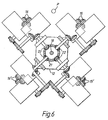
- the second embodiment illustrates a four strand finishing block having four finishing lines disposed radially around a horizontal path provided by the input drive shaft 18.
- Two opposing input bevel gears 21 are mounted on the input drive shaft 18 in the same way as the first embodiment.
- the transmission bevel gears 22 of two radially opposite finishing lines are meshed with the downstream input bevel gear 21 to couple the upper right and the lower left finishing lines to the drive shaft 18.
- the upper left and lower right twin roll finishing lines are similarly coupled to the downstream input bevel gear.
- Each finishing line is similar to the finishing line described in respect of the first embodiment.
- a similar drive driven from a common drive source, can be provided for a three strand finishing block.
Landscapes
- Engineering & Computer Science (AREA)
- Mechanical Engineering (AREA)
- Metal Rolling (AREA)
- Reduction Rolling/Reduction Stand/Operation Of Reduction Machine (AREA)
- Coating With Molten Metal (AREA)
- Metal Extraction Processes (AREA)
- Crystals, And After-Treatments Of Crystals (AREA)
- Perforating, Stamping-Out Or Severing By Means Other Than Cutting (AREA)
- Dry Formation Of Fiberboard And The Like (AREA)
Claims (3)
- Fertigbearbeitungsstraße zum simultanen Walzen von mindestens zwei Stangensträngen, enthaltend für jeden Strang (5,5') mehrere Walzenpaare (15V, 15H, 20V, 20H), die in Tandemanordnung angeordnet sind, wobei die Walzen jedes Paares in rechtem Winkel zu den Walzen des Paares oder jedes Paares angeordnet sind, welches oder welche benachbart zu diesem Paar vorgesehen sind, und wobei alle Walzenpaare durch einen Antriebsmotor (19) angetrieben werden, der mechanisch mit ihnen verbunden ist,
dadurch gekennzeichnet, daß sämtliche Walzenpaare an zwei oder mehr ähnlichen Fertigbearbeitungsblöcken (12A, 12B) vorgesehen sind, die in Tandemanordnung vorgesehen sind, wobei jeder Block für jeden Strang zwei Walzenpaare (15V, 15H, 16H, 16V) vorsieht, die wechselseitig im rechten Winkel angeordnet sind, wobei jeder Block eine einzelne Antriebswelle (18) aufweist, die in Antriebsverbindung mit sämtlichen Walzenpaaren des Blockes steht, und wobei die Antriebswellen dieser Blöcke lösbar in Reihe mit dem Antriebsmotor (19) verbunden sind. - Fertigbearbeitungsstraße nach Anspruch 1,
dadurch gekennzeichnet, daß sich die Stangenstränge entlang getrennter, parallel zu einander verlaufender Wege (5,5') erstrecken, die von einem weiteren Weg (17) beabstandet sind, und daß die Achse der Welle (18) auf diesem weiteren Weg (17) angeordnet ist. - Fertigbearbeitungsstraße nach Anspruch 2,
bei der vier parallele Wege vorgesehen sind und bei der zwei der parallelen Wege auf einem niedrigeren Niveau als der weitere Weg angeordnet sind.
Applications Claiming Priority (3)
| Application Number | Priority Date | Filing Date | Title |
|---|---|---|---|
| GB9422451A GB9422451D0 (en) | 1994-11-07 | 1994-11-07 | A multi strand finishing block |
| GB9422451 | 1994-11-07 | ||
| PCT/GB1995/002565 WO1996014174A1 (en) | 1994-11-07 | 1995-11-02 | A multi-strand finishing block |
Publications (2)
| Publication Number | Publication Date |
|---|---|
| EP0790868A1 EP0790868A1 (de) | 1997-08-27 |
| EP0790868B1 true EP0790868B1 (de) | 2000-03-29 |
Family
ID=10764018
Family Applications (1)
| Application Number | Title | Priority Date | Filing Date |
|---|---|---|---|
| EP95935528A Expired - Lifetime EP0790868B1 (de) | 1994-11-07 | 1995-11-02 | Mehradriges fertigwalzblock |
Country Status (12)
| Country | Link |
|---|---|
| US (1) | US6161412A (de) |
| EP (1) | EP0790868B1 (de) |
| JP (1) | JP3165446B2 (de) |
| KR (1) | KR100229161B1 (de) |
| CN (1) | CN1072990C (de) |
| AT (1) | ATE191163T1 (de) |
| CA (1) | CA2204729A1 (de) |
| DE (1) | DE69516011D1 (de) |
| GB (1) | GB9422451D0 (de) |
| TW (1) | TW339289B (de) |
| WO (1) | WO1996014174A1 (de) |
| ZA (1) | ZA959370B (de) |
Families Citing this family (6)
| Publication number | Priority date | Publication date | Assignee | Title |
|---|---|---|---|---|
| US5893288A (en) * | 1997-04-25 | 1999-04-13 | Morgan Construction Company | Multiple outlet finishing mill |
| DE10022168A1 (de) * | 2000-05-06 | 2001-11-08 | Sms Demag Ag | Walzgerüstanordnung für das Walzen von Draht oder Feineisen |
| ITPN20010012A1 (it) * | 2001-02-15 | 2002-08-16 | Sms Demag Aktiengesellshaft | Blocco compatto di laminazione per due linee parallele. |
| US7191629B1 (en) | 2006-04-13 | 2007-03-20 | Morgan Construction Company | Modular rolling mill |
| CN104889162B (zh) * | 2015-06-19 | 2017-07-04 | 石家庄中利锌业有限公司 | 多丝道连铸连轧锌丝生产线 |
| CN114260311B (zh) * | 2021-10-26 | 2024-01-26 | 中冶南方工程技术有限公司 | 一种高产量棒材生产系统 |
Family Cites Families (4)
| Publication number | Priority date | Publication date | Assignee | Title |
|---|---|---|---|---|
| SE321910B (de) * | 1964-11-07 | 1970-03-23 | Demag Ag | |
| GB1127771A (en) * | 1965-02-04 | 1968-09-18 | Davy & United Eng Co Ltd | Rolling mills |
| DE2160629A1 (de) * | 1970-12-17 | 1972-07-06 | Oppenheim, Samuel, Udine (Italien) | Kombinierte kontinuierliche Walzstraße für Feinstahl |
| US5307663A (en) * | 1993-01-12 | 1994-05-03 | Morgan Construction Company | Multiple outlet finishing mill |
-
1994
- 1994-11-07 GB GB9422451A patent/GB9422451D0/en active Pending
-
1995
- 1995-11-02 KR KR1019970702188A patent/KR100229161B1/ko not_active Expired - Fee Related
- 1995-11-02 WO PCT/GB1995/002565 patent/WO1996014174A1/en not_active Ceased
- 1995-11-02 JP JP51512896A patent/JP3165446B2/ja not_active Expired - Fee Related
- 1995-11-02 US US08/817,870 patent/US6161412A/en not_active Expired - Lifetime
- 1995-11-02 CN CN95196091A patent/CN1072990C/zh not_active Expired - Fee Related
- 1995-11-02 AT AT95935528T patent/ATE191163T1/de not_active IP Right Cessation
- 1995-11-02 DE DE69516011T patent/DE69516011D1/de not_active Expired - Fee Related
- 1995-11-02 EP EP95935528A patent/EP0790868B1/de not_active Expired - Lifetime
- 1995-11-02 CA CA002204729A patent/CA2204729A1/en not_active Abandoned
- 1995-11-06 ZA ZA959370A patent/ZA959370B/xx unknown
- 1995-12-04 TW TW084112886A patent/TW339289B/zh active
Also Published As
| Publication number | Publication date |
|---|---|
| GB9422451D0 (en) | 1995-01-04 |
| ATE191163T1 (de) | 2000-04-15 |
| TW339289B (en) | 1998-09-01 |
| WO1996014174A1 (en) | 1996-05-17 |
| DE69516011D1 (de) | 2000-05-04 |
| US6161412A (en) | 2000-12-19 |
| EP0790868A1 (de) | 1997-08-27 |
| CN1072990C (zh) | 2001-10-17 |
| CA2204729A1 (en) | 1996-05-17 |
| KR970706084A (ko) | 1997-11-03 |
| KR100229161B1 (ko) | 1999-11-01 |
| JP3165446B2 (ja) | 2001-05-14 |
| ZA959370B (en) | 1996-07-08 |
| JPH10511895A (ja) | 1998-11-17 |
| CN1162938A (zh) | 1997-10-22 |
Similar Documents
| Publication | Publication Date | Title |
|---|---|---|
| EP1844867B1 (de) | Modulares Walzwerk | |
| DE102009050710B4 (de) | Drahtwalzgerüst mit Einzelantrieb | |
| KR100231280B1 (ko) | 압연기 | |
| US6161412A (en) | Multi-strand finishing block | |
| EP0933145B1 (de) | Optionales mehrstufiges Getriebesystem | |
| CN212442579U (zh) | 一种单机架独立传动模块化轧机及机组 | |
| CN102814336B (zh) | 顶交45°连轧机组的传动装置 | |
| US6546776B2 (en) | High speed finishing block | |
| US5060499A (en) | Rolling stand with multiple rolls supported as cantilevers for high-speed rolling | |
| US8171767B2 (en) | Modular rolling mill | |
| EP2673097B1 (de) | Maschine zum warmwalzen von walzdrähten und dergleichen | |
| CN202951701U (zh) | 顶交45°连轧机组 | |
| EP2747911A1 (de) | Walzdraht und maschine zum warmwalzen von walzdrähten |
Legal Events
| Date | Code | Title | Description |
|---|---|---|---|
| PUAI | Public reference made under article 153(3) epc to a published international application that has entered the european phase |
Free format text: ORIGINAL CODE: 0009012 |
|
| 17P | Request for examination filed |
Effective date: 19970606 |
|
| AK | Designated contracting states |
Kind code of ref document: A1 Designated state(s): AT BE CH DE ES FR GB IT LI LU PT |
|
| 17Q | First examination report despatched |
Effective date: 19980716 |
|
| GRAG | Despatch of communication of intention to grant |
Free format text: ORIGINAL CODE: EPIDOS AGRA |
|
| GRAG | Despatch of communication of intention to grant |
Free format text: ORIGINAL CODE: EPIDOS AGRA |
|
| GRAH | Despatch of communication of intention to grant a patent |
Free format text: ORIGINAL CODE: EPIDOS IGRA |
|
| GRAH | Despatch of communication of intention to grant a patent |
Free format text: ORIGINAL CODE: EPIDOS IGRA |
|
| GRAA | (expected) grant |
Free format text: ORIGINAL CODE: 0009210 |
|
| AK | Designated contracting states |
Kind code of ref document: B1 Designated state(s): AT BE CH DE ES FR GB IT LI LU PT |
|
| PG25 | Lapsed in a contracting state [announced via postgrant information from national office to epo] |
Ref country code: LI Free format text: LAPSE BECAUSE OF FAILURE TO SUBMIT A TRANSLATION OF THE DESCRIPTION OR TO PAY THE FEE WITHIN THE PRESCRIBED TIME-LIMIT Effective date: 20000329 Ref country code: FR Free format text: LAPSE BECAUSE OF FAILURE TO SUBMIT A TRANSLATION OF THE DESCRIPTION OR TO PAY THE FEE WITHIN THE PRESCRIBED TIME-LIMIT Effective date: 20000329 Ref country code: ES Free format text: THE PATENT HAS BEEN ANNULLED BY A DECISION OF A NATIONAL AUTHORITY Effective date: 20000329 Ref country code: CH Free format text: LAPSE BECAUSE OF FAILURE TO SUBMIT A TRANSLATION OF THE DESCRIPTION OR TO PAY THE FEE WITHIN THE PRESCRIBED TIME-LIMIT Effective date: 20000329 Ref country code: BE Free format text: LAPSE BECAUSE OF FAILURE TO SUBMIT A TRANSLATION OF THE DESCRIPTION OR TO PAY THE FEE WITHIN THE PRESCRIBED TIME-LIMIT Effective date: 20000329 Ref country code: AT Free format text: LAPSE BECAUSE OF FAILURE TO SUBMIT A TRANSLATION OF THE DESCRIPTION OR TO PAY THE FEE WITHIN THE PRESCRIBED TIME-LIMIT Effective date: 20000329 |
|
| REF | Corresponds to: |
Ref document number: 191163 Country of ref document: AT Date of ref document: 20000415 Kind code of ref document: T |
|
| REG | Reference to a national code |
Ref country code: CH Ref legal event code: EP |
|
| REF | Corresponds to: |
Ref document number: 69516011 Country of ref document: DE Date of ref document: 20000504 |
|
| ITF | It: translation for a ep patent filed | ||
| PG25 | Lapsed in a contracting state [announced via postgrant information from national office to epo] |
Ref country code: PT Free format text: LAPSE BECAUSE OF FAILURE TO SUBMIT A TRANSLATION OF THE DESCRIPTION OR TO PAY THE FEE WITHIN THE PRESCRIBED TIME-LIMIT Effective date: 20000629 |
|
| EN | Fr: translation not filed | ||
| REG | Reference to a national code |
Ref country code: CH Ref legal event code: PL |
|
| PG25 | Lapsed in a contracting state [announced via postgrant information from national office to epo] |
Ref country code: LU Free format text: LAPSE BECAUSE OF NON-PAYMENT OF DUE FEES Effective date: 20001102 |
|
| PLBE | No opposition filed within time limit |
Free format text: ORIGINAL CODE: 0009261 |
|
| STAA | Information on the status of an ep patent application or granted ep patent |
Free format text: STATUS: NO OPPOSITION FILED WITHIN TIME LIMIT |
|
| 26N | No opposition filed | ||
| REG | Reference to a national code |
Ref country code: GB Ref legal event code: IF02 |
|
| PGFP | Annual fee paid to national office [announced via postgrant information from national office to epo] |
Ref country code: DE Payment date: 20031202 Year of fee payment: 9 |
|
| PG25 | Lapsed in a contracting state [announced via postgrant information from national office to epo] |
Ref country code: DE Free format text: LAPSE BECAUSE OF NON-PAYMENT OF DUE FEES Effective date: 20050601 |
|
| PG25 | Lapsed in a contracting state [announced via postgrant information from national office to epo] |
Ref country code: IT Free format text: LAPSE BECAUSE OF NON-PAYMENT OF DUE FEES Effective date: 20071102 |
|
| PGFP | Annual fee paid to national office [announced via postgrant information from national office to epo] |
Ref country code: GB Payment date: 20121115 Year of fee payment: 18 Ref country code: IT Payment date: 20121129 Year of fee payment: 18 |
|
| GBPC | Gb: european patent ceased through non-payment of renewal fee |
Effective date: 20131102 |
|
| PG25 | Lapsed in a contracting state [announced via postgrant information from national office to epo] |
Ref country code: IT Free format text: LAPSE BECAUSE OF NON-PAYMENT OF DUE FEES Effective date: 20131102 |
|
| PG25 | Lapsed in a contracting state [announced via postgrant information from national office to epo] |
Ref country code: GB Free format text: LAPSE BECAUSE OF NON-PAYMENT OF DUE FEES Effective date: 20131102 |