EP0790871B1 - Procede et appareil de fabrication de produits helicoidaux - Google Patents
Procede et appareil de fabrication de produits helicoidaux Download PDFInfo
- Publication number
- EP0790871B1 EP0790871B1 EP95936002A EP95936002A EP0790871B1 EP 0790871 B1 EP0790871 B1 EP 0790871B1 EP 95936002 A EP95936002 A EP 95936002A EP 95936002 A EP95936002 A EP 95936002A EP 0790871 B1 EP0790871 B1 EP 0790871B1
- Authority
- EP
- European Patent Office
- Prior art keywords
- angle
- rollers
- forming members
- helix
- forming
- Prior art date
- Legal status (The legal status is an assumption and is not a legal conclusion. Google has not performed a legal analysis and makes no representation as to the accuracy of the status listed.)
- Expired - Lifetime
Links
- 238000000034 method Methods 0.000 title claims abstract description 31
- 238000004519 manufacturing process Methods 0.000 title abstract description 8
- 239000000463 material Substances 0.000 claims abstract description 47
- 238000005452 bending Methods 0.000 claims description 9
- 239000012212 insulator Substances 0.000 abstract description 13
- 241001131696 Eurystomus Species 0.000 description 30
- 230000015572 biosynthetic process Effects 0.000 description 4
- 230000007246 mechanism Effects 0.000 description 4
- 238000009434 installation Methods 0.000 description 3
- 239000004020 conductor Substances 0.000 description 2
- 238000005520 cutting process Methods 0.000 description 2
- 230000008569 process Effects 0.000 description 2
- 241001131639 Eurystomus orientalis Species 0.000 description 1
- 229910000831 Steel Inorganic materials 0.000 description 1
- 230000008859 change Effects 0.000 description 1
- 230000007423 decrease Effects 0.000 description 1
- 238000005304 joining Methods 0.000 description 1
- 238000002372 labelling Methods 0.000 description 1
- 238000010330 laser marking Methods 0.000 description 1
- 238000012423 maintenance Methods 0.000 description 1
- 239000002184 metal Substances 0.000 description 1
- 238000007639 printing Methods 0.000 description 1
- 230000007420 reactivation Effects 0.000 description 1
- 238000005507 spraying Methods 0.000 description 1
- 239000010959 steel Substances 0.000 description 1
- 238000003466 welding Methods 0.000 description 1
Images



Classifications
-
- H—ELECTRICITY
- H02—GENERATION; CONVERSION OR DISTRIBUTION OF ELECTRIC POWER
- H02G—INSTALLATION OF ELECTRIC CABLES OR LINES, OR OF COMBINED OPTICAL AND ELECTRIC CABLES OR LINES
- H02G7/00—Overhead installations of electric lines or cables
- H02G7/05—Suspension arrangements or devices for electric cables or lines
- H02G7/06—Suspensions for lines or cables along a separate supporting wire, e.g. S-hook
- H02G7/10—Flexible members or lashings wrapped around both the supporting wire and the line or cable
-
- B—PERFORMING OPERATIONS; TRANSPORTING
- B21—MECHANICAL METAL-WORKING WITHOUT ESSENTIALLY REMOVING MATERIAL; PUNCHING METAL
- B21D—WORKING OR PROCESSING OF SHEET METAL OR METAL TUBES, RODS OR PROFILES WITHOUT ESSENTIALLY REMOVING MATERIAL; PUNCHING METAL
- B21D11/00—Bending not restricted to forms of material mentioned in only one of groups B21D5/00, B21D7/00, B21D9/00; Bending not provided for in groups B21D5/00 - B21D9/00; Twisting
- B21D11/06—Bending into helical or spiral form; Forming a succession of return bends, e.g. serpentine form
Definitions
- This invention relates to a method and an apparatus for manufacturing helical products (including but not limited to insulator ties and dead-ends).
- the dead-ends may be constructed of either plastic rods or a flat ribbon or strip of material such as steel. Following separate formation of the two helical legs and a U-shaped bight of each dead-end, the three elements are joined by welding or clamping them together.
- the dead-ends may also contain knurled or gritted surfaces to enhance their ability to grip cables, although no mechanism for knurling the appropriate surfaces is disclosed in either the '491 patent or in U.S. Patent No. 3,183,658 to which it refers.
- each leg is created by forming an elongated helical strip and then cutting the strip to the desired length.
- Another continuous strip is formed into "continuous generally sine wave type undulations.” with "each individual undulation corresponding to the desired configuration" of the bight of the resulting dead-end.
- the undulating strip is cut to define multiple bights, one of which may then be joined to the helical legs as noted above to create the dead-end.
- the pitch lengths of the two helical legs differ.
- the first leg (having longer pitch) is wrapped about a cable, with the second leg thereafter wrapped about both the cable and the first leg.
- the helixes of the first leg purportedly provide a body of a relatively uniform and more rigid contour for the helixes of the second leg to grip, while the second leg is intended to clamp the surface of the first leg tightly about the cable.
- Neither the '491 patent nor the '397 patent contemplates manufacturing both the helical and bight portions of dead-ends from a continuous strip of material. Similarly, neither patent discloses forming other appliances useful in connection with cable installations or any mechanism for knurling such appliances in-line.
- the '491 and '397 patents additionally neither teach nor suggest devices having legs of equal pitch length, each intended to wrap around a conductor or other cable. Instead, as discussed therein, the leg of the dead-end of the '491 and '397 patents having the shorter pitch is wrapped around the other leg to diminish excessive localized radial pressures that otherwise purportedly would occur.
- FR-A-706920 discloses apparatus in which strip material is urged to press against selected pairs of rollers disposed at an angle to the direction of travel of the strip material.
- One of the rollers carries a shoulder against which an edge of the strip material bears.
- the strip material is deformed by contact with the rollers into the form of a helix.
- the present invention provides a method for forming helical sections in strip material, the method comprising the steps of:-
- the present invention further provides apparatus for performing the above mentioned method comprising
- the forming members may comprise spaced rollers with rotational axes angularly disposed to the first direction to lie parallel with the second direction.
- This invention thereby provides a method and an apparatus for forming helical devices of many types (including dead-ends and insulator ties).
- the components of resulting helical devices may be formed continuously from a single strip rather than separately manufactured. Doing so avoids the need to weld or clamp the components together, reducing the possibility of stresses or non-uniformities forming during their joining. It also decreases the manual labor often involved in manufacturing existing dead-ends, permitting continuous automatic or semi-automatic manufacture to occur.
- the present invention manipulates a continuous flat strip or other suitable material to form both helical and non-helical sections. Feeding the strip initially to a pair of forming members, the invention permits devices of differing pitch lengths and helix diameters to be formed, for example by adjusting the angle between feed and forming axes and the distance between the forming members. Such adjustments can occur automatically, moreover, by connecting the forming members to suitable controllers.
- the present invention contemplate forming devices having sections of identical pitch length, the invention is not so limited and may be used to produce devices of variable pitch length and helix diameter.
- the present invention is useful in forming insulator ties and other equipment typically associated with conductive cables.
- the forming rollers may be deactivated to retain a straight section of the device.
- other rollers may be employed to bend, or redirect, the straight section along the same axis as that of the prior helical portion.
- the first helical leg may simply be bent back to the original feed axis. In either event, maintaining the same axis of travel for both the helical and non-helical sections of the device prevents it from effectively becoming a giant flywheel as it rotates during the forming process.
- the forming rollers are thereafter reactivated to form the second helical leg of the device, and a cutting mechanism may be used to separate adjacent devices.
- the straight section of the strip subsequently is manually or automatically bent to form the bight of the completed dead-end. If a knurled surface is desired for the dead-end, it may be formed in-line using a knurling wheel actuated hydraulically or otherwise.
- the present invention allows the manufacture of devices formed of continuous segments of the strip, avoiding the need to weld, clamp, or otherwise join their component parts, so leading to improved speed and cost of manufacture and to improved physical characteristics.
- FIGS. 1-2 illustrate schematically apparatus 10 in accordance with the present invention.
- Apparatus 10 includes drive section 14, comprising one or more pairs of opposed drive wheels 18, and guides 22.
- the design of drive section 14 permits material 26, typically (but not necessarily) a flat strip of metal, to pass therethrough in the direction of feed arrow 30.
- Appropriate positioning of the drive wheels 18 and guides 22 reduces the likelihood that material 26 will buckle or otherwise deform when fed to apparatus 10.
- Guides 22 also may be used to straighten material 26 in one or more dimensions, thereby reducing warps and curves that might otherwise be present.
- knurling of at least portions of its surface may be desired. As detailed in the schematic representations of FIGS. 1-2, this knurling may be accomplished by including in apparatus 10 a retractable knurl wheel 34.
- knurl wheel 34 is shown contacting material 26, producing thereon knurls suitable to enhance the grip of material 26 about a cable or other object.
- knurl wheel 34 is retracted so as not to contact material 26.
- knurl wheel 34 may be attached to hydraulic cylinder 38 to permit such retraction.
- pneumatic cylinders or other actuators may be used to move knurl wheel 34 relative to material 26.
- knurl wheel 34 is shown schematically opposite drive wheel 18A and intermediate drive wheels 18 and guides 22, it may be positioned elsewhere as necessary or appropriate to achieve the soughtafter results.
- Other apparatus may be installed to mark the strip surface, e.g. with part numbers or trade marks, by any known method - for example by laser marking, printing, spraying, stamping or labelling.
- forming section 42 illustrated in FIGS. 3 and 3A as including top forming roller 42A and bottom forming roller 42B having longitudinal axis C.
- forming rollers 42A and 42B are retractable and thus may be deactivated when desired.
- forming section 42 may comprise a single top forming roller 42A, with bottom forming roller 42B replaced by a support or, perhaps, the trailing edge or portion of guides 22.
- rollers 42A and 42B When activated, forming rollers 42A and 42B impart a helical shape unto the material 26 passing therethrough by bending and twisting the material 26.
- the distance D between forming rollers 42A and 42B may determine the diameter of helix 46 formed in material 26 so that, helixes of different diameters may be formed merely by adjusting that distance D.
- An alternative approach is to vary the angle F between a plane containing the rotational axes of the rollers 42A and 42B and the direction of travel of material 26. This may be done in combination with adjusting distance D.
- Rollers 42A and 42B simultaneously change the direction of travel of material 26 by an angle B, causing material 26 to range along longitudinal axis C rather than the original feed axis A.
- helixes 46 of different pitch lengths may be created by adjusting the angle B between longitudinal axis C and feed axis A.
- angle B By connecting forming rollers 42A and 42B to suitable controlling equipment, moreover, such adjustment of distance D and angle B may occur automatically.
- angle B By making angle B negative, helixes 46 having an opposite lay direction may be formed.
- each part of the strip material is passed through the rollers it is bent away from its initial direction of travel and twisted.
- the bending is to an extent determined by the distance D and the twisting is to an extent determined by the angle B. It is this bending and twisting that produces the helix.
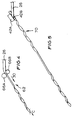
- apparatus 10 of the present invention may also include redirection rollers 66A and 66B as shown in Fig.4. Of differing diameters, opposed rollers 66A and 66B bend, or guide, non-helical section 62 along longitudinal axis C. Alternatively, helix 46 could simply be bent back to the original feed axis A.
- redirection rollers 66A and 66B are retractable, permitting them to be employed as necessary during operation of apparatus 10.
- servo motors, hydraulics, pneumatics, or any other suitable mechanism may be used to retract and reactivate any or all of forming rollers 42A and 42B and redirection rollers 66A and 66B.
- Material 26 typically does not advance through apparatus 10 while such retractions and reactivations occur, although with existing controllers these actions can be performed almost instantaneously.
- Deactivating rollers 66A and 66B and reactivating forming rollers 42A and 42B produces another helix 70.
- a single set of rollers may be used for this purpose and moved from a forming position to a redirection position.
- adjusting the angle B and the distance D between forming rollers 42A and 42B permits helical devices of differing pitch lengths and helix diameters to be formed, with the adjustment occurring automatically (even during formation of a single helix 46 or 70) if desired.
- the portion of material 26 to be used for a dead-end 50 or an insulator tie 54 or 58 is cut after helix 70 is formed, thereby producing a helical device having non-helical section 62 intermediate helixes 46 and 70 and permitting continuous formation of the next such device.
- FIG. 6 illustrates a dead-end 50 produced with the method of the present invention.
- Dead-end 50 is formed of a continuous strip of material 26 and comprises helix 46, helix 70, and non-helical section 62. Although generally straight when exiting apparatus 10, non-helical section 62 of dead-end 50 has been curved (either manually or using other equipment) to form bight 74 and so that leg 78 (comprising helix 46) is approximately parallel to leg 82 (comprising helix 70).
- leg 78 comprising helix 46
- leg 82 comprising helix 70
- the pitch length of helixes 46 and 70 is 2.85" (about 72.4mm), while the outer diameter (the sum of the helix diameter and twice the thickness of the flat strip) of each of helixes 46 and 70 is 0.457" (about 11.6mm).
- the strip may be, for example. 0.05" (about 1.3mm) to 0.5" (about 12.7mm) thick and of a width 0.1" (about 2.5mm) to 1" (about 25.4mm) wide with the ratio of thickness to width between 2 and 10.
- FIGS. 7 and 7A detail an exemplary insulator "top” tie 54 in which non-helical section 62 has been bent into bight 74 in the shape of an "S.”
- Nominal pitch lengths and outer diameters for such a tie may be 5.50" (about 139.7mm) and 1.004" (about 25.5mm), respectively
- FIG. 8 shows an insulator "side” tie 58 of the present invention.
- non-helical section 62 has been bent through approximately 300 to form bight 74. This produces a nominal angle E of approximately 120 between legs 78 and 82.
- Exemplary pitch lengths and outer diameters for helixes 46 and 70 of tie 58 are, respectively, 4.00" (about 101.6mm) and 0.683" (about 17.3mm).
- legs 78 and 82 typically wrap around a conductor or other cable to grip it securely, if present, the knurled surfaces of legs 78 and 82 may enhance the grip and thereby provide an even more effective product.
- the helical products produced with the method of the present invention may be formed of a continuous strip of material (whether flat, round, or otherwise) and are not limited to two-legged devices such as dead-ends and insulator ties. Instead, with the method of the invention virtually any elongated device intended to have one or more discontinuities along its length can be produced.
Landscapes
- Mechanical Engineering (AREA)
- Engineering & Computer Science (AREA)
- Shaping Of Tube Ends By Bending Or Straightening (AREA)
- Extrusion Moulding Of Plastics Or The Like (AREA)
- Wire Processing (AREA)
- Clamps And Clips (AREA)
- Connector Housings Or Holding Contact Members (AREA)
- Manufacturing Of Electrical Connectors (AREA)
- Insulating Bodies (AREA)
- Lining Or Joining Of Plastics Or The Like (AREA)
- Iron Core Of Rotating Electric Machines (AREA)
- Processing And Handling Of Plastics And Other Materials For Molding In General (AREA)
- Jellies, Jams, And Syrups (AREA)
- Treatments Of Macromolecular Shaped Articles (AREA)
Claims (19)
- Procédé de formation de sections hélicoïdales (46, 70) d'un matériau en bande, le procédé comportant les étapes consistant à :a) délivrer le matériau en bande, dans une première direction (A), au contact d'une paire d'éléments de formation (42A, 42B);b) les éléments de formation (42A, 42B) opérant pour recourber et imprimer une torsion à la bande pour former une section hélicoïdale (46, 70) laissant les éléments de formation (42A, 42B) dans une seconde direction (C), le degré de courbure déterminant le diamètre de l'hélice et le degré de torsion déterminant l'angle d'hélice de l'hélice,
caractérisée en ce quec) le matériau en bande passe, à partir d'un côté de la paire d'éléments de formation (42A, 42B), entre la paire d'éléments de formation (42A, 42B), pour sortir de l'autre côté de la paire d'éléments de formation (42A, 42B). - Procédé selon la revendication 1, caractérisé en ce que le degré de torsion est déterminé par l'angle entre la première (A) et la seconde (C) direction.
- Procédé selon la revendication 1 ou la revendication 2, caractérisé en ce que les éléments de formation (42A, 42B) comportent une paire de galets espacés (42A, 42B) dont les axes de rotation sont disposés avec un angle par rapport à la première direction (A) afin de s'étendre parallèlement à la seconde direction (C).
- Procédé selon la revendication 3, caractérisé en ce que l'espacement (D) entre les galets (42A, 42B) est sélectivement variable pour pouvoir modifier le degré de courbure.
- Procédé selon la revendication 3 ou la revendication 4, caractérisé en ce que l'angle (F), entre le plan contenant les ces de rotation des galets (42A, 42B) et la première direction (A), est sélectivement variable afin de pouvoir faire varier le degré de courbure.
- Procédé selon une quelconque des revendications 3 à 5, caractérisé en ce que l'angle entre la direction (B) de disposition des ces de rotation des galets espacés (42A, 42B) et la première direction, et donc l'angle entre la première (A) et la seconde (C) direction, est sélectivement variable afin de pouvoir faire varier le degré de torsion.
- Procédé selon une quelconque des revendications précédentes, caractérisé en ce que les éléments de formation (42A, 42B) peuvent être sélectivement désengagés de façon à produire sélectivement une section non-hélicoïdale (62) à partir du matériau en bande au voisinage d'une section hélicoïdale (46, 70).
- Procédé selon une quelconque des revendications 4 à 7, caractérisé en ce que l'espacement (D) entre les galets (42A, 42B) et/ou l'angle (F), entre le plan contenant les axes de rotation des galets (42A, 42B) et la première direction, est variable pendant la formation de l'hélice de sorte qu'il est possible de faire varier le diamètre de ladite hélice.
- Procédé selon une quelconque des revendications 4 à 8, caractérisé en ce que l'angle entre la direction de disposition (B) des ces de rotation des galets espacés (42A, 42B) et la première direction (A), et donc l'angle entre la première (A) et la seconde (C) direction, est variable pendant la formation de l'hélice de sorte qu'il est possible de faire varier le pas de ladite hélice.
- Appareil pour mettre en oeuvre l'invention selon la revendication 1, caractérisé en ce qu'il comporte :a) des moyens pour délivrer le matériau en bande dans une première direction (A) au contactb) d'une paire d'éléments de formation (42A, 42B) pouvant fonctionner pour recourber et imprimer une torsion à la bande afin de former une section hélicoïdale (46, 70) laissant les éléments de formation (42A, 42B) dans une seconde direction (C), l'angle entre la première (A) et la seconde (C) direction déterminant l'angle d'hélice de la section hélicoïdale (46, 70)
caractérisé en ce quec) les éléments de formation (42A, 42B) sont disposés de telle sorte que le matériau en bande passe, à partir d'un côté de la paire d'éléments de formation (42A, 42B), entre la paire d'éléments de formation (42A, 42B), pour sortir de l'autre côté de la paire d'éléments de formation (42A, 42B). - Appareil selon la revendication 10, caractérisé en ce que les éléments de formation (42A, 42B) comportent une paire de galets espacés (42A, 42B) dont les axes de rotation sont disposés avec un angle par rapport à la première direction (A) afin de s'étendre parallèlement à la seconde direction (C).
- Appareil selon la revendication 11, caractérisé en ce que l'espacement (D) entre les galets (42A, 42B) est sélectivement variable pour pouvoir modifier le degré de courbure.
- Appareil selon la revendication 11 ou la revendication 12, caractérisé en ce que l'angle (F) entre le plan contenant les axes de rotation des galets (42A, 42B) et la première direction est sélectivement variable pour pouvoir faire varier le degré de courbure.
- Appareil selon une quelconque des revendications 11 à 13, caractérisé en ce que l'angle entre la direction de disposition (B) des ces de rotation des galets espacés (42A, 42B) et la première direction (A), et donc l'angle entre la première (A) et la seconde (C) direction, est sélectivement variable pour pouvoir faire varier le degré de torsion.
- Appareil selon une quelconque des revendications 10 à 14, caractérisé en ce que les éléments de formation (42A, 42B) peuvent être désengagés sélectivement de façon à produire sélectivement une section non-hélicoïdale (62) à partir du matériau en bande au voisinage d'une section hélicoïdale (46, 70).
- Appareil selon une quelconque des revendications 12 à 15, caractérisé en ce que l'espacement (D) entre les galets (42A, 42B) et/ou l'angle (F), entre le plan contenant les ces de rotation des galets (42A, 42B) et la première direction, est capable de varier pendant que l'hélice est formée de sorte qu'il est possible de faire varier le diamètre de ladite hélice.
- Appareil selon une quelconque des revendications 12 à 16, caractérisé en ce que l'angle entre la direction de disposition (B) des ces de rotation des galets espacés (42A, 42B) et la première direction (A), et donc l'angle entre la première (A) et la seconde (C) direction, est capable de varier pendant que l'hélice est formée de sorte qu'il est possible de faire varier le pas de ladite hélice.
- Procédé selon une quelconque des revendications 1 à 9, caractérisé en ce qu'il comporte l'étape consistant à moleter le matériau en bande.
- Appareil selon une quelconque des revendications 10 à 17, caractérisé en ce qu'il comporte des moyens pour moleter le matériau en bande.
Priority Applications (1)
| Application Number | Priority Date | Filing Date | Title |
|---|---|---|---|
| EP98104685A EP0850706B1 (fr) | 1994-11-04 | 1995-10-24 | Procédé et appareil de fabrication de produits hélicoidaux |
Applications Claiming Priority (3)
| Application Number | Priority Date | Filing Date | Title |
|---|---|---|---|
| US08/334,136 US5586461A (en) | 1994-11-04 | 1994-11-04 | Methods and apparatus for manufacturing helical products |
| US334136 | 1994-11-04 | ||
| PCT/GB1995/002511 WO1996014176A1 (fr) | 1994-11-04 | 1995-10-24 | Procedes et appareil de fabrication de produits helicoidaux |
Related Child Applications (1)
| Application Number | Title | Priority Date | Filing Date |
|---|---|---|---|
| EP98104685A Division EP0850706B1 (fr) | 1994-11-04 | 1995-10-24 | Procédé et appareil de fabrication de produits hélicoidaux |
Publications (2)
| Publication Number | Publication Date |
|---|---|
| EP0790871A1 EP0790871A1 (fr) | 1997-08-27 |
| EP0790871B1 true EP0790871B1 (fr) | 1999-04-21 |
Family
ID=23305751
Family Applications (2)
| Application Number | Title | Priority Date | Filing Date |
|---|---|---|---|
| EP98104685A Expired - Lifetime EP0850706B1 (fr) | 1994-11-04 | 1995-10-24 | Procédé et appareil de fabrication de produits hélicoidaux |
| EP95936002A Expired - Lifetime EP0790871B1 (fr) | 1994-11-04 | 1995-10-24 | Procede et appareil de fabrication de produits helicoidaux |
Family Applications Before (1)
| Application Number | Title | Priority Date | Filing Date |
|---|---|---|---|
| EP98104685A Expired - Lifetime EP0850706B1 (fr) | 1994-11-04 | 1995-10-24 | Procédé et appareil de fabrication de produits hélicoidaux |
Country Status (16)
| Country | Link |
|---|---|
| US (1) | US5586461A (fr) |
| EP (2) | EP0850706B1 (fr) |
| JP (1) | JPH10508538A (fr) |
| CN (1) | CN1070395C (fr) |
| AT (2) | ATE214980T1 (fr) |
| AU (2) | AU691685B2 (fr) |
| BR (1) | BR9509554A (fr) |
| CA (1) | CA2204139A1 (fr) |
| DE (2) | DE69526125T2 (fr) |
| ES (2) | ES2132727T3 (fr) |
| MX (1) | MX9703126A (fr) |
| MY (1) | MY115446A (fr) |
| NZ (1) | NZ294882A (fr) |
| TW (1) | TW272292B (fr) |
| WO (1) | WO1996014176A1 (fr) |
| ZA (1) | ZA959294B (fr) |
Families Citing this family (5)
| Publication number | Priority date | Publication date | Assignee | Title |
|---|---|---|---|---|
| US5927125A (en) * | 1994-11-04 | 1999-07-27 | The Morgan Crucible Company Plc | Methods and apparatus for manufacturing helical products |
| GB2305303B (en) * | 1996-02-09 | 1997-08-06 | Morgan Crucible Co | Cable suspension devices |
| GB2325508B (en) * | 1997-05-23 | 1999-04-21 | Morgan Crucible Co | Helical products |
| GB2338118B (en) * | 1998-05-29 | 2002-03-20 | Preformed Line Products Co | Helical fitting components for the securing of covered conductor and method of production thereof |
| CN110444338B (zh) * | 2019-07-09 | 2020-11-20 | 东莞市智钢五金电子有限公司 | 一种数据线编织印花生产线 |
Family Cites Families (17)
| Publication number | Priority date | Publication date | Assignee | Title |
|---|---|---|---|---|
| FR706920A (fr) * | 1930-08-27 | 1931-07-01 | Sleeper & Hartley Inc | Perfectionnements aux machines pour enroulement en forme d'hélice |
| US1914976A (en) * | 1930-08-27 | 1933-06-20 | Sleeper & Hartley Inc | Machine for coiling helical forms |
| US2192260A (en) * | 1938-09-14 | 1940-03-05 | Sleeper & Hartley Inc | Wire coiling machine |
| US2888726A (en) * | 1956-05-04 | 1959-06-02 | Sr Burt A Smith | Lead-in wire connectors |
| US2912816A (en) * | 1957-08-13 | 1959-11-17 | Indiana Steel & Wire Company I | Dead-end |
| US3018319A (en) * | 1959-09-25 | 1962-01-23 | Jackson C Quayle | Compression dead end splice |
| FR1251118A (fr) * | 1960-03-14 | 1961-01-13 | Preformed Line Products Co | Dispositif d'attache de ligne électrique |
| GB1022295A (en) * | 1962-11-07 | 1966-03-09 | Smith & Sons Ltd S | Improvements in or relating to the manufacture of tube like structures |
| FR1347755A (fr) * | 1962-11-14 | 1964-01-04 | Ct De Rech S De Pont A Mousson | Procédé et dispositif perfectionnés pour l'enroulement continu de fil métallique |
| US3183658A (en) * | 1962-11-20 | 1965-05-18 | John D Drinko | Preformed helical appliance for linear bodies |
| US3646793A (en) * | 1968-09-09 | 1972-03-07 | Tatsuo Teraoka | Device for manufacturing a helically preformed element |
| US3847491A (en) * | 1971-10-18 | 1974-11-12 | Preformed Line Products Co | Appliance for linear bodies |
| US3800397A (en) * | 1972-07-03 | 1974-04-02 | Preformed Line Products Co | Method for making appliance for linear bodies |
| US4015073A (en) * | 1976-01-02 | 1977-03-29 | A. B. Chance Company | Universal line tie and method of making same |
| CA1127729A (fr) * | 1978-06-02 | 1982-07-13 | Gary R. Dickerson | Pince-fil boudine prefaconne a divers diametres primitifs a l'endroit de chaque spire |
| US4546631A (en) * | 1983-04-01 | 1985-10-15 | Foster Wheeler Energy Corporation | Roller mechanism for forming helical shapes |
| US5105642A (en) * | 1990-07-30 | 1992-04-21 | L&P Property Management Company | Continuous coil spring forming method |
-
1994
- 1994-11-04 US US08/334,136 patent/US5586461A/en not_active Expired - Fee Related
-
1995
- 1995-05-03 TW TW084104482A patent/TW272292B/zh active
- 1995-10-24 BR BR9509554A patent/BR9509554A/pt not_active IP Right Cessation
- 1995-10-24 DE DE69526125T patent/DE69526125T2/de not_active Expired - Fee Related
- 1995-10-24 AT AT98104685T patent/ATE214980T1/de not_active IP Right Cessation
- 1995-10-24 ES ES95936002T patent/ES2132727T3/es not_active Expired - Lifetime
- 1995-10-24 DE DE69509251T patent/DE69509251T2/de not_active Expired - Fee Related
- 1995-10-24 EP EP98104685A patent/EP0850706B1/fr not_active Expired - Lifetime
- 1995-10-24 WO PCT/GB1995/002511 patent/WO1996014176A1/fr not_active Ceased
- 1995-10-24 CN CN95197055A patent/CN1070395C/zh not_active Expired - Fee Related
- 1995-10-24 JP JP8515118A patent/JPH10508538A/ja active Pending
- 1995-10-24 EP EP95936002A patent/EP0790871B1/fr not_active Expired - Lifetime
- 1995-10-24 ES ES98104685T patent/ES2172047T3/es not_active Expired - Lifetime
- 1995-10-24 CA CA002204139A patent/CA2204139A1/fr not_active Abandoned
- 1995-10-24 NZ NZ294882A patent/NZ294882A/en unknown
- 1995-10-24 AU AU38095/95A patent/AU691685B2/en not_active Ceased
- 1995-10-24 MX MX9703126A patent/MX9703126A/es not_active IP Right Cessation
- 1995-10-24 AT AT95936002T patent/ATE179099T1/de not_active IP Right Cessation
- 1995-11-03 ZA ZA959294A patent/ZA959294B/xx unknown
- 1995-11-04 MY MYPI95003341A patent/MY115446A/en unknown
-
1998
- 1998-03-23 AU AU59461/98A patent/AU694907B2/en not_active Ceased
Also Published As
| Publication number | Publication date |
|---|---|
| JPH10508538A (ja) | 1998-08-25 |
| EP0790871A1 (fr) | 1997-08-27 |
| CA2204139A1 (fr) | 1996-05-17 |
| CN1070395C (zh) | 2001-09-05 |
| DE69526125T2 (de) | 2002-10-31 |
| ZA959294B (en) | 1996-05-29 |
| HK1002063A1 (en) | 1998-07-31 |
| CN1171067A (zh) | 1998-01-21 |
| TW272292B (en) | 1996-03-11 |
| ATE214980T1 (de) | 2002-04-15 |
| ATE179099T1 (de) | 1999-05-15 |
| WO1996014176A1 (fr) | 1996-05-17 |
| MX9703126A (es) | 1997-06-28 |
| AU691685B2 (en) | 1998-05-21 |
| EP0850706B1 (fr) | 2002-03-27 |
| DE69509251T2 (de) | 1999-11-25 |
| DE69509251D1 (de) | 1999-05-27 |
| BR9509554A (pt) | 1997-09-16 |
| US5586461A (en) | 1996-12-24 |
| MY115446A (en) | 2003-06-30 |
| EP0850706A3 (fr) | 1998-11-11 |
| AU5946198A (en) | 1998-05-28 |
| DE69526125D1 (de) | 2002-05-02 |
| ES2172047T3 (es) | 2002-09-16 |
| EP0850706A2 (fr) | 1998-07-01 |
| ES2132727T3 (es) | 1999-08-16 |
| NZ294882A (en) | 1998-08-26 |
| AU3809595A (en) | 1996-05-31 |
| AU694907B2 (en) | 1998-07-30 |
Similar Documents
| Publication | Publication Date | Title |
|---|---|---|
| US4650924A (en) | Ribbon cable, method and apparatus, and electromagnetic device | |
| US5133121A (en) | Stranded electric conductor manufacture | |
| US4033387A (en) | Method of making a reinforcing strip | |
| US20140367146A1 (en) | Apparatus and Method for Forming Wire | |
| US5927125A (en) | Methods and apparatus for manufacturing helical products | |
| EP0850706B1 (fr) | Procédé et appareil de fabrication de produits hélicoidaux | |
| DE69107503T2 (de) | Metallrohrherstellung. | |
| HK1002063B (en) | Method and apparatus for manufacturing helical products | |
| HK1009108A (en) | Method and apparatus for manufacturing helical products | |
| NZ330054A (en) | Producing helical devices from strip material comprises forming two helical sections and a central non-helical section | |
| JP2001234486A (ja) | スチールコード及びゴム複合体 | |
| EP0070977B1 (fr) | Appareil et procédé pour former une armure de protection extérieure sur un tuyau flexible | |
| DE69107502T2 (de) | Metallrohrherstellung. | |
| CA2412678C (fr) | Procede de ligne d'assemblage permettant de produire des bobines d'armature et procede de production de celles-ci | |
| KR20010072342A (ko) | 광 도파관의 길이가 연장된 광 케이블 제조 방법 | |
| CA1177699A (fr) | Methode de faconnage d'un tube lisse a partir d'un feuillard | |
| US6377736B1 (en) | Helical products and method of manufacturing of same for engagement with a cable | |
| DE2632986B2 (de) | Verfahren zur Herstellung eines Kabels mit einer leitenden konzentrischen Mantelschicht und Vorrichtung zur Durchführung des Verfahrens | |
| DE69106357T2 (de) | Verfahren zur Herstellung einer Verseileinheit mit abschnittsweise wechselnder Drallrichtung. | |
| JPS6031122B2 (ja) | 高周波伝送路用螺旋状波付き導体管の製造方法 | |
| WO2000026008A1 (fr) | Procede et dispositif de texturation de tube flexible | |
| JPS5852411B2 (ja) | 螺線状電線支持具の製造方法 | |
| GB2093082A (en) | Method of making flexible tubular guide sheaths for coaxial push-pull actuator cables and cable sheaths produced thereby | |
| JPH0857978A (ja) | ゴムクロ−ラ用スチ−ルコ−ドバンドの製造法及びその製造装置 | |
| JP2007176389A (ja) | タイヤ用ゴムシ−ト |
Legal Events
| Date | Code | Title | Description |
|---|---|---|---|
| PUAI | Public reference made under article 153(3) epc to a published international application that has entered the european phase |
Free format text: ORIGINAL CODE: 0009012 |
|
| 17P | Request for examination filed |
Effective date: 19970506 |
|
| AK | Designated contracting states |
Kind code of ref document: A1 Designated state(s): AT DE ES FR GB IT |
|
| 17Q | First examination report despatched |
Effective date: 19970912 |
|
| GRAG | Despatch of communication of intention to grant |
Free format text: ORIGINAL CODE: EPIDOS AGRA |
|
| GRAG | Despatch of communication of intention to grant |
Free format text: ORIGINAL CODE: EPIDOS AGRA |
|
| GRAG | Despatch of communication of intention to grant |
Free format text: ORIGINAL CODE: EPIDOS AGRA |
|
| GRAH | Despatch of communication of intention to grant a patent |
Free format text: ORIGINAL CODE: EPIDOS IGRA |
|
| GRAH | Despatch of communication of intention to grant a patent |
Free format text: ORIGINAL CODE: EPIDOS IGRA |
|
| GRAA | (expected) grant |
Free format text: ORIGINAL CODE: 0009210 |
|
| AK | Designated contracting states |
Kind code of ref document: B1 Designated state(s): AT DE ES FR GB IT |
|
| REF | Corresponds to: |
Ref document number: 179099 Country of ref document: AT Date of ref document: 19990515 Kind code of ref document: T |
|
| REF | Corresponds to: |
Ref document number: 69509251 Country of ref document: DE Date of ref document: 19990527 |
|
| ET | Fr: translation filed | ||
| REG | Reference to a national code |
Ref country code: ES Ref legal event code: FG2A Ref document number: 2132727 Country of ref document: ES Kind code of ref document: T3 |
|
| PLBE | No opposition filed within time limit |
Free format text: ORIGINAL CODE: 0009261 |
|
| STAA | Information on the status of an ep patent application or granted ep patent |
Free format text: STATUS: NO OPPOSITION FILED WITHIN TIME LIMIT |
|
| 26N | No opposition filed | ||
| REG | Reference to a national code |
Ref country code: GB Ref legal event code: IF02 |
|
| PGFP | Annual fee paid to national office [announced via postgrant information from national office to epo] |
Ref country code: AT Payment date: 20051004 Year of fee payment: 11 |
|
| PGFP | Annual fee paid to national office [announced via postgrant information from national office to epo] |
Ref country code: FR Payment date: 20051017 Year of fee payment: 11 |
|
| PGFP | Annual fee paid to national office [announced via postgrant information from national office to epo] |
Ref country code: GB Payment date: 20051019 Year of fee payment: 11 |
|
| PGFP | Annual fee paid to national office [announced via postgrant information from national office to epo] |
Ref country code: ES Payment date: 20051026 Year of fee payment: 11 |
|
| PGFP | Annual fee paid to national office [announced via postgrant information from national office to epo] |
Ref country code: DE Payment date: 20051130 Year of fee payment: 11 |
|
| PG25 | Lapsed in a contracting state [announced via postgrant information from national office to epo] |
Ref country code: AT Free format text: LAPSE BECAUSE OF NON-PAYMENT OF DUE FEES Effective date: 20061024 |
|
| PGFP | Annual fee paid to national office [announced via postgrant information from national office to epo] |
Ref country code: IT Payment date: 20061031 Year of fee payment: 12 |
|
| PG25 | Lapsed in a contracting state [announced via postgrant information from national office to epo] |
Ref country code: DE Free format text: LAPSE BECAUSE OF NON-PAYMENT OF DUE FEES Effective date: 20070501 |
|
| GBPC | Gb: european patent ceased through non-payment of renewal fee |
Effective date: 20061024 |
|
| REG | Reference to a national code |
Ref country code: FR Ref legal event code: ST Effective date: 20070629 |
|
| PG25 | Lapsed in a contracting state [announced via postgrant information from national office to epo] |
Ref country code: GB Free format text: LAPSE BECAUSE OF NON-PAYMENT OF DUE FEES Effective date: 20061024 |
|
| REG | Reference to a national code |
Ref country code: ES Ref legal event code: FD2A Effective date: 20061025 |
|
| PG25 | Lapsed in a contracting state [announced via postgrant information from national office to epo] |
Ref country code: FR Free format text: LAPSE BECAUSE OF NON-PAYMENT OF DUE FEES Effective date: 20061031 Ref country code: ES Free format text: LAPSE BECAUSE OF NON-PAYMENT OF DUE FEES Effective date: 20061025 |
|
| PG25 | Lapsed in a contracting state [announced via postgrant information from national office to epo] |
Ref country code: IT Free format text: LAPSE BECAUSE OF NON-PAYMENT OF DUE FEES Effective date: 20071024 |