EP0791290A2 - Geregelter Durchflussbegrenzer für Tropfbewässerung - Google Patents
Geregelter Durchflussbegrenzer für Tropfbewässerung Download PDFInfo
- Publication number
- EP0791290A2 EP0791290A2 EP97630013A EP97630013A EP0791290A2 EP 0791290 A2 EP0791290 A2 EP 0791290A2 EP 97630013 A EP97630013 A EP 97630013A EP 97630013 A EP97630013 A EP 97630013A EP 0791290 A2 EP0791290 A2 EP 0791290A2
- Authority
- EP
- European Patent Office
- Prior art keywords
- passageway
- flow
- body member
- baffles
- clearances
- Prior art date
- Legal status (The legal status is an assumption and is not a legal conclusion. Google has not performed a legal analysis and makes no representation as to the accuracy of the status listed.)
- Granted
Links
- 230000001105 regulatory effect Effects 0.000 title claims abstract description 11
- 238000003973 irrigation Methods 0.000 title claims abstract description 9
- 230000002262 irrigation Effects 0.000 title claims abstract description 8
- 239000012530 fluid Substances 0.000 claims abstract description 25
- 230000000694 effects Effects 0.000 claims abstract description 6
- 239000003638 chemical reducing agent Substances 0.000 claims description 4
- 239000013536 elastomeric material Substances 0.000 claims description 4
- 230000003247 decreasing effect Effects 0.000 claims description 3
- 238000011144 upstream manufacturing Methods 0.000 claims 1
- XLYOFNOQVPJJNP-UHFFFAOYSA-N water Substances O XLYOFNOQVPJJNP-UHFFFAOYSA-N 0.000 description 24
- 238000010276 construction Methods 0.000 description 12
- 230000004048 modification Effects 0.000 description 4
- 238000012986 modification Methods 0.000 description 4
- 239000012528 membrane Substances 0.000 description 2
- 238000007599 discharging Methods 0.000 description 1
- 238000006073 displacement reaction Methods 0.000 description 1
- 238000001914 filtration Methods 0.000 description 1
- 239000003621 irrigation water Substances 0.000 description 1
Images


Classifications
-
- A—HUMAN NECESSITIES
- A01—AGRICULTURE; FORESTRY; ANIMAL HUSBANDRY; HUNTING; TRAPPING; FISHING
- A01G—HORTICULTURE; CULTIVATION OF VEGETABLES, FLOWERS, RICE, FRUIT, VINES, HOPS OR SEAWEED; FORESTRY; WATERING
- A01G25/00—Watering gardens, fields, sports grounds or the like
- A01G25/02—Watering arrangements located above the soil which make use of perforated pipe-lines or pipe-lines with dispensing fittings, e.g. for drip irrigation
- A01G25/023—Dispensing fittings for drip irrigation, e.g. drippers
-
- Y—GENERAL TAGGING OF NEW TECHNOLOGICAL DEVELOPMENTS; GENERAL TAGGING OF CROSS-SECTIONAL TECHNOLOGIES SPANNING OVER SEVERAL SECTIONS OF THE IPC; TECHNICAL SUBJECTS COVERED BY FORMER USPC CROSS-REFERENCE ART COLLECTIONS [XRACs] AND DIGESTS
- Y02—TECHNOLOGIES OR APPLICATIONS FOR MITIGATION OR ADAPTATION AGAINST CLIMATE CHANGE
- Y02A—TECHNOLOGIES FOR ADAPTATION TO CLIMATE CHANGE
- Y02A40/00—Adaptation technologies in agriculture, forestry, livestock or agroalimentary production
- Y02A40/10—Adaptation technologies in agriculture, forestry, livestock or agroalimentary production in agriculture
- Y02A40/22—Improving land use; Improving water use or availability; Controlling erosion
Definitions
- the present invention relates to regulated flow restrictor devices.
- the invention represents an improvement in the flow restrictor devices described in my prior Patent No. 5,400,971, and is therefore described below with respect to such use.
- My prior Patent No. 5,400,971 describes a regulated flow-restrictor device particularly useful as a drip irrigation emitter, comprising a body member including a flow-regulating passageway shaving an inlet end to communicate with a source of pressurized fluid, and an outlet end for outletting the fluid; the flow-regulating passageway including a plurality of baffles and a deformable elastomeric element having a first face cooperable with the baffles and a second face exposed to a pressure varying with that of the fluid source, the baffles producing a flowpath having a series of bypass clearances which restrict the flow of the fluid through the passageway; the elastomeric element being deformable in response to fluid pressure on said second face to close the clearances sequentially in the direction from one of the passageway ends towards the other of the passageway ends with an increase in fluid pressure to maintain a substantially uniform flow to the outlet end of the passageway.
- the sequential closing of clearances is effected by constructiing the baffles in the flow-regulating passageway so tha they define, with the elastomeric element of the flow-regulating passageway, clearances of increasing height which are sequentially closed by the deformation of the elastomeric element in response to an increase in the fluid pressure.
- elastomeric element is constructed and supported so as to be non-uniformly deformable along its length in response to and increased in the fluid pressure on its second face to effect the sequential closing of the clearances.
- one end of the elastomeric element experiences a larger displacement than the opposite end for any particular pressure, such that with progressively increasing pressure, the membrane is progressively deformed along its length to effect the sequential closing of the clearances.
- the drip-irrigation emitter illustrated in Figs. 1-3 comprises a plastic tube 2 for conducting irrigation water under pressure and is formed with a plurality of openings 6 spaced along its length for discharging the water.
- a pressure-regulated, flow-restrictor device 10 is disposed within tube 2 for each of the discharge openings 6.
- Each flow-restrictor device 10 reduces the pressure of the water discharged from its opening 6 to substantially atmospheric pressure, and also regulates the flow through the discharge opening with variations in the pressure of the water within the tube.
- Each pressure-regulated flow-restrictor device 10 is constituted of a one-piece body member 11 made of elastomeric material and of cylindrical configuration received within tube 2.
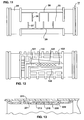
- the outer face of elastomeric body member 11 is formed on one side with a pressure-reducing passageway 12 (Fig. 4) to reduce the water pressure and flow rate through outlet opening 6, and on the opposite side with a flow-regulating passageway 13 (Fig. 5) to compensate the water flow through outlet opneing 6 for variations in the water pressure.
- Passageway 12 (Fig. 4) includes a plurality of baffles 14 which define, with the inner surface of tube 2, a labyrinth-type pressure-reducing passageway.
- Passageway 13 on the opposite side of body member 11 includes a plurality of baffles 15 which define, also with the inner surface of tube 2, a labyrinth-type flow-regulating passageway which varies in accordance with pressure to maintain a substantially uniform outlet rate despite variations in the water pressure within the tube 2.
- the water enters from the interior 4 of tube 2 via a plurality of narrow slits 16 defining filter-type inlet openings leading into a pair of recesses 17, 18 (Fig. 4) straddling the pressure-reducer passageway 12.
- Recess 18 has a circumferential extension 18a and joins with recess 17 at the inlet end 19 of the pressure-reducer passageway 12.
- the outlet end of passageway 12 is in the form of another recess 20 which extends circumferentially to the opposite side of body member 11.
- Recess 20 leads to another recess 21 (Fig. 5) which constitutes the inlet end of the flow-regulating passageway 13.
- the outlet end of the latter passageway is also in the form of a recess 22 which leads to an annular recess 23 at one end of body member 11.
- the opposite end of body member 11 is formed with a similar annular recess 24 which communicates with annular recess 23 by a passageway 25.
- passageway 25 is defined by two sets of spaced, parallel circumferential ribs 26, 27. Ribs 26 are connected at one end to an axial rib 28, and ribs 27 are connected at one end to another axial rib 29. Ribs 26 terminate short of axial rib 29, whereas ribs 27 terminate short of axial rib 28, to thereby provide passageway 25 connecting together the two annular recesses 23 and 24.
- the flow-regulating passageway 13 regulates the flow from its inlet end 21 to its outlet end 22 in order to compensate for variations in the pressure of the water within the tube 2.
- This is done in basically the same manner as described in my above-cited Patent 5,400,971, by sequentially closing clearances defined by the baffles 15 in the flow-regulating passageway 13 with the inner surface of tube 2.
- these clearances shown at 30 in Figs. 1 and 3, are sequentially closed from the inlet end 21 toward the outlet end 22 of the flow-regulating passageway 13 in response to an increase in the pressure of the water within tube 2. It will be appreciated, however, that these clearances could be sequentially closed from the outlet end 22 towards the inlet end 21, as described in my above-cited Patent 5,400,971.
- the baffles are constructed to produce clearances of different heights which are sequentially closed in response to the pressure of the water.
- the strip of the elastomeric material in the flow-regulating passageway 13 is constructed and supported such that the elastomeric strip is non-uniformly deformable along its length in response to the fluid pressure whereby, with an increase in the fluid pressure, the elastomeric strip is progressively deformed along its length to effect the sequential closing of the clearances 30.
- baffles 15 may define clearances 30 which are of the same heights.
- the outer face of the elastomeric body member 11 is formed with a pair of spaced recesses 31, 32 (Figs. 3 and 5) straddling baffles 15 within the flow-regulating passageway 13.
- Recesses 31, 32 define a strip containing those baffles and connected to the remainder of the cylindrical body member 11 by yieldable webs 31a, 32a, respectively, which permit the strip containing baffles 15 to deform or bend according to the fluid pressure. As shown in Fig.
- recess 31 is of varying depth, as is recess 32 on the opposite side of the baffles 15, such that the webs 31a, 32a, connecting the strip containing the baffles 15 with the remainder of the body member 11, are of increasing thickness from the inlet end 21 of the flow-regulating passageway 13 to the outlet end 22 as shown in Figs. 8-10.
- Recess 20 leads to the inlet end 21 (Fig. 5) of the flow-regulating passageway 13.
- This passageway regulates the flow rate by sequentially closing the clearances 30 of its labyrinth, defined by baffles 15 and the inner surface of tube 2, in response to variations in the pressure of the water within tube 2 as described earlier.
- the water exits from passageway 13 via its outlet end 22 into annular recess 23 at one end of body member 11, and into annular recess 24 at the opposite end of body member 11, via passageway 25 (Fig. 11) defined by the ribs 26-29.
- outlet openings 6 in tube 2 would be aligned with annular recess 23 and/or annular recess 24, so that the water, after passing through both the flow-reducing passageway 12 and the flow-regulating passageway 13, would be discharged at the slow regulated rate.
- Fig. 12 illustrates another construction of the body member in the drip irrigation emitter of Figs. 1-11.
- the pair of recesses, therein shown as 131, 132 straddling the baffles 115 of the flow-regulating passageway 113 in the body member 111 are not of uniform width and of varying depth as in the construction described above with respect to Figs. 1-11, but rather are of varying width and of uniform depth, the width decreasing from the inlet end of the flow-regulating passageway 113 towards the outlet end 122 of that passageway.
- the webs defined by these recesses permit a greater deflection of the strip of the elastomeric body member formed with the flow-regulating passageway 113 at the outlet end 122 of that passageway than at the inlet end 121.
- the effect is gradual progression of this deflection, and therefore a sequential closing of the clearances in passageway 113, from the inlet end 121 to the outlet end 122, with increasing water pressure.
- Fig. 13 illustrates a variation in the construction of Fig. 12, wherein the recesses (corresponding to recesses 131 and 132 in Fig. 12) not only decrease in width, but also increase in depth, from the inlet end 221 to the outlet end 222, of the flow-regulating passageway 213.
- the webs 233 defined by these recesses are therefore of increased thickness from the inlet end 221 to the outlet end 222 of passageway 213 to contribute to the sequential closing of the clearances with increasing water pressure.
- the construction and operation of the drip irrigation emitter illustrated in Fig. 13 are substantially the same as described above with respect to Figs. 12 and Figs. 1-11.
- the baffles 15 defining the clearances in the flow-regulating passageway are flat.
- Fig. 14 illustrates a modification, wherein these baffles 15' are inwardly tapered at their ends 15a defining the sides of the flow-regulating passageway, and are flat, as shown at 15b, in the mid portions of that passageway.
Landscapes
- Life Sciences & Earth Sciences (AREA)
- Soil Sciences (AREA)
- Engineering & Computer Science (AREA)
- Water Supply & Treatment (AREA)
- Environmental Sciences (AREA)
- Nozzles (AREA)
- Infusion, Injection, And Reservoir Apparatuses (AREA)
- Safety Valves (AREA)
Applications Claiming Priority (2)
| Application Number | Priority Date | Filing Date | Title |
|---|---|---|---|
| IL11732696A IL117326A (en) | 1996-03-01 | 1996-03-01 | Regulated flow-restrictor devices particularly useful in drip irrigation |
| IL11732696 | 1996-03-01 |
Publications (3)
| Publication Number | Publication Date |
|---|---|
| EP0791290A2 true EP0791290A2 (de) | 1997-08-27 |
| EP0791290A3 EP0791290A3 (de) | 1997-09-03 |
| EP0791290B1 EP0791290B1 (de) | 2003-09-03 |
Family
ID=11068612
Family Applications (1)
| Application Number | Title | Priority Date | Filing Date |
|---|---|---|---|
| EP97630013A Expired - Lifetime EP0791290B1 (de) | 1996-03-01 | 1997-02-28 | Geregelter Durchflussbegrenzer für Tropfbewässerung |
Country Status (4)
| Country | Link |
|---|---|
| US (1) | US5829685A (de) |
| EP (1) | EP0791290B1 (de) |
| ES (1) | ES2205155T3 (de) |
| IL (1) | IL117326A (de) |
Cited By (6)
| Publication number | Priority date | Publication date | Assignee | Title |
|---|---|---|---|---|
| EP1435196A3 (de) * | 1997-10-14 | 2004-11-17 | Hydroplan Engineering Ltd. | Verbesserter Tropfbewässerungsauslass |
| EP1448313A4 (de) * | 2001-11-26 | 2008-03-05 | Amir Cohen | Tropfbewässerungsschlauch und herstellungsverfahren dafür |
| GB2496832A (en) * | 2011-05-16 | 2013-05-29 | Uri Alkalay | Cylindrical drip irrigation emitter system |
| WO2013109285A1 (en) * | 2012-01-20 | 2013-07-25 | Halliburton Energy Services, Inc. | Pressure pulse-initiated flow restrictor bypass system |
| US8573311B2 (en) | 2012-01-20 | 2013-11-05 | Halliburton Energy Services, Inc. | Pressure pulse-initiated flow restrictor bypass system |
| US9428989B2 (en) | 2012-01-20 | 2016-08-30 | Halliburton Energy Services, Inc. | Subterranean well interventionless flow restrictor bypass system |
Families Citing this family (42)
| Publication number | Priority date | Publication date | Assignee | Title |
|---|---|---|---|---|
| US6213408B1 (en) | 1999-11-18 | 2001-04-10 | Eureka Technologies Ltd | Flow regulator and corresponding method with pressure responsive flow regulation |
| US6655207B1 (en) * | 2000-02-16 | 2003-12-02 | Honeywell International Inc. | Flow rate module and integrated flow restrictor |
| US6817548B2 (en) * | 2001-09-05 | 2004-11-16 | R.M. Wade & Co. | Fluid distribution emitter and system |
| US6736337B2 (en) * | 2002-02-08 | 2004-05-18 | The Toro Company | Pressure compensating drip irrigation hose |
| US8302887B2 (en) | 2005-03-31 | 2012-11-06 | Rain Bird Corporation | Drip emitter |
| US7648085B2 (en) | 2006-02-22 | 2010-01-19 | Rain Bird Corporation | Drip emitter |
| US7735758B2 (en) * | 2006-09-18 | 2010-06-15 | Amir Cohen | Drip irrigation hoses of the labyrinth type and flow-control elements for producing such hoses |
| US7454984B1 (en) * | 2007-08-31 | 2008-11-25 | Delphi Technologies, Inc. | Flow meter for measuring a flow rate of a flow of a fluid |
| US7988076B2 (en) | 2008-10-20 | 2011-08-02 | D.R.T.S. Enterprises Ltd. | Non-clogging non-pressure compensated drip emitter |
| US8628032B2 (en) | 2008-12-31 | 2014-01-14 | Rain Bird Corporation | Low flow irrigation emitter |
| US8317111B2 (en) * | 2010-01-31 | 2012-11-27 | Amirim Products Development & Patents Ltd. | Bi-component drip emitter |
| US8113046B2 (en) | 2010-03-22 | 2012-02-14 | Honeywell International Inc. | Sensor assembly with hydrophobic filter |
| US8397586B2 (en) | 2010-03-22 | 2013-03-19 | Honeywell International Inc. | Flow sensor assembly with porous insert |
| US8656772B2 (en) | 2010-03-22 | 2014-02-25 | Honeywell International Inc. | Flow sensor with pressure output signal |
| US8756990B2 (en) | 2010-04-09 | 2014-06-24 | Honeywell International Inc. | Molded flow restrictor |
| US9003877B2 (en) | 2010-06-15 | 2015-04-14 | Honeywell International Inc. | Flow sensor assembly |
| US8418549B2 (en) | 2011-01-31 | 2013-04-16 | Honeywell International Inc. | Flow sensor assembly with integral bypass channel |
| US8695417B2 (en) | 2011-01-31 | 2014-04-15 | Honeywell International Inc. | Flow sensor with enhanced flow range capability |
| IL212105A (en) * | 2011-04-03 | 2016-07-31 | Einav Zvi | Integral dropper with elongated exit pool |
| US10440903B2 (en) | 2012-03-26 | 2019-10-15 | Rain Bird Corporation | Drip line emitter and methods relating to same |
| US9877440B2 (en) * | 2012-03-26 | 2018-01-30 | Rain Bird Corporation | Elastomeric emitter and methods relating to same |
| US20130248622A1 (en) * | 2012-03-26 | 2013-09-26 | Jae Yung Kim | Drip line and emitter and methods relating to same |
| US9485923B2 (en) | 2012-03-26 | 2016-11-08 | Rain Bird Corporation | Elastomeric emitter and methods relating to same |
| US9052217B2 (en) | 2012-11-09 | 2015-06-09 | Honeywell International Inc. | Variable scale sensor |
| US9872444B2 (en) | 2013-03-15 | 2018-01-23 | Rain Bird Corporation | Drip emitter |
| US10285342B2 (en) * | 2013-08-12 | 2019-05-14 | Rain Bird Corporation | Elastomeric emitter and methods relating to same |
| US10631473B2 (en) * | 2013-08-12 | 2020-04-28 | Rain Bird Corporation | Elastomeric emitter and methods relating to same |
| USD811179S1 (en) | 2013-08-12 | 2018-02-27 | Rain Bird Corporation | Emitter part |
| US9883640B2 (en) | 2013-10-22 | 2018-02-06 | Rain Bird Corporation | Methods and apparatus for transporting elastomeric emitters and/or manufacturing drip lines |
| US10330559B2 (en) | 2014-09-11 | 2019-06-25 | Rain Bird Corporation | Methods and apparatus for checking emitter bonds in an irrigation drip line |
| US9952079B2 (en) | 2015-07-15 | 2018-04-24 | Honeywell International Inc. | Flow sensor |
| JP6577318B2 (ja) * | 2015-10-01 | 2019-09-18 | 株式会社エンプラス | エミッタおよび点滴灌漑用チューブ |
| US10070595B2 (en) * | 2015-11-03 | 2018-09-11 | THE Machines Yvonand S.A. | Drip irrigation tube having dosing elements inserted therein |
| US10375904B2 (en) | 2016-07-18 | 2019-08-13 | Rain Bird Corporation | Emitter locating system and related methods |
| US11051466B2 (en) | 2017-01-27 | 2021-07-06 | Rain Bird Corporation | Pressure compensation members, emitters, drip line and methods relating to same |
| US10626998B2 (en) | 2017-05-15 | 2020-04-21 | Rain Bird Corporation | Drip emitter with check valve |
| USD883048S1 (en) | 2017-12-12 | 2020-05-05 | Rain Bird Corporation | Emitter part |
| US11985924B2 (en) | 2018-06-11 | 2024-05-21 | Rain Bird Corporation | Emitter outlet, emitter, drip line and methods relating to same |
| US11452269B2 (en) | 2019-06-14 | 2022-09-27 | The Toro Company | Rail tuned pressure responsive irrigation emitter |
| US11933417B2 (en) | 2019-09-27 | 2024-03-19 | Rain Bird Corporation | Irrigation sprinkler service valve |
| US12030072B2 (en) | 2020-11-16 | 2024-07-09 | Rain Bird Corporation | Pressure regulation device and method for irrigation sprinklers |
| US12207599B2 (en) | 2021-10-12 | 2025-01-28 | Rain Bird Corporation | Emitter coupler and irrigation system |
Family Cites Families (7)
| Publication number | Priority date | Publication date | Assignee | Title |
|---|---|---|---|---|
| US5183208A (en) * | 1990-07-20 | 1993-02-02 | Agroteam Consultants Ltd. | Drip irrigation emitter |
| US5236130A (en) * | 1991-03-15 | 1993-08-17 | Lego M. Lemelshtrich Ltd. | Drip irrigation apparatus |
| US5400973A (en) * | 1993-07-30 | 1995-03-28 | Cohen; Amir | Pressure responsive regulated flow restrictor useful for drip irrigation |
| US5634594A (en) * | 1993-07-30 | 1997-06-03 | Cohen; Amir | Flow control device particularly useful in drip irrigation emitters |
| US5636797A (en) * | 1993-07-30 | 1997-06-10 | Cohen; Amir | Drip irrigation emitter and flow control unit included therein |
| US5615838A (en) * | 1995-03-10 | 1997-04-01 | Drip Irrigation Systems, Ltd. | In-line retention drip emitter |
| US5628462A (en) * | 1995-08-15 | 1997-05-13 | Miller; David B. | Drip irrigation emitter |
-
1996
- 1996-03-01 IL IL11732696A patent/IL117326A/xx not_active IP Right Cessation
-
1997
- 1997-02-26 US US08/805,416 patent/US5829685A/en not_active Expired - Lifetime
- 1997-02-28 ES ES97630013T patent/ES2205155T3/es not_active Expired - Lifetime
- 1997-02-28 EP EP97630013A patent/EP0791290B1/de not_active Expired - Lifetime
Cited By (8)
| Publication number | Priority date | Publication date | Assignee | Title |
|---|---|---|---|---|
| EP1435196A3 (de) * | 1997-10-14 | 2004-11-17 | Hydroplan Engineering Ltd. | Verbesserter Tropfbewässerungsauslass |
| EP1448313A4 (de) * | 2001-11-26 | 2008-03-05 | Amir Cohen | Tropfbewässerungsschlauch und herstellungsverfahren dafür |
| GB2496832A (en) * | 2011-05-16 | 2013-05-29 | Uri Alkalay | Cylindrical drip irrigation emitter system |
| GB2496832B (en) * | 2011-05-16 | 2013-11-13 | Uri Alkalay | Cylindrical drip irrigation emitter |
| US9918438B2 (en) | 2011-05-16 | 2018-03-20 | Uri Alkalay | Cylindrical drip irrigation emitter |
| WO2013109285A1 (en) * | 2012-01-20 | 2013-07-25 | Halliburton Energy Services, Inc. | Pressure pulse-initiated flow restrictor bypass system |
| US8573311B2 (en) | 2012-01-20 | 2013-11-05 | Halliburton Energy Services, Inc. | Pressure pulse-initiated flow restrictor bypass system |
| US9428989B2 (en) | 2012-01-20 | 2016-08-30 | Halliburton Energy Services, Inc. | Subterranean well interventionless flow restrictor bypass system |
Also Published As
| Publication number | Publication date |
|---|---|
| US5829685A (en) | 1998-11-03 |
| ES2205155T3 (es) | 2004-05-01 |
| IL117326A0 (en) | 1996-07-23 |
| EP0791290B1 (de) | 2003-09-03 |
| EP0791290A3 (de) | 1997-09-03 |
| IL117326A (en) | 1999-11-30 |
Similar Documents
| Publication | Publication Date | Title |
|---|---|---|
| EP0791290B1 (de) | Geregelter Durchflussbegrenzer für Tropfbewässerung | |
| US5236130A (en) | Drip irrigation apparatus | |
| EP0636309B1 (de) | Regulierte Durchflussbegrenzungsvorrichtung insbesondere Verwendbar als Tropfbewässerungsauslass | |
| US6206305B1 (en) | Irrigation emitter unit | |
| US4687143A (en) | Drip irrigation apparatus | |
| US5586727A (en) | Flow reducer devices and drip irrigation emitter including same | |
| US4655397A (en) | Vortex dripper | |
| RU2126300C1 (ru) | Способ преобразования подаваемого под давлением непрерывного потока малого расхода в пульсирующий поток большого расхода и устройство для его осуществления | |
| US7954732B2 (en) | Irrigation system and method | |
| KR920012667A (ko) | 세류(細流) 관개 튜브 | |
| US4190206A (en) | Drip irrigation system | |
| MA25272A1 (fr) | Tuyau d'irrigation goutte a goutte muni d'enbouts pour differents debits. | |
| IL97564A (en) | Drip irrigation apparatus | |
| US5141029A (en) | Variable orifice device | |
| TW341617B (en) | Variable area restrictor and turbine engine comprising the same | |
| US4225438A (en) | Support member for use with semipermeable membrane | |
| GB2133860A (en) | Fluid flow control device particularly useful as a drip irrigation emitter | |
| EP0414977B1 (de) | Kleine Zerstäuber für die Bewässerung | |
| DE3275971D1 (en) | Pressure relief valve for the fluid of a sphygmomanometer | |
| US4008157A (en) | End seal construction for semipermeable membrane | |
| IL119447A (en) | Current limiting regulator for special use as a drip irrigation emitter | |
| SU1550484A1 (ru) | Регул тор расхода | |
| DE2328882A1 (de) | Druckabhaengige drehzahlsteuerung fuer zahnaerztliche griffstuecke | |
| SU1671197A1 (ru) | Водовыпускной микрогидрант | |
| FI91672B (fi) | Menetelmä ja laite ilmavirtauksen jakamiseksi |
Legal Events
| Date | Code | Title | Description |
|---|---|---|---|
| PUAI | Public reference made under article 153(3) epc to a published international application that has entered the european phase |
Free format text: ORIGINAL CODE: 0009012 |
|
| PUAL | Search report despatched |
Free format text: ORIGINAL CODE: 0009013 |
|
| AK | Designated contracting states |
Kind code of ref document: A2 Designated state(s): ES FR GR IT |
|
| AK | Designated contracting states |
Kind code of ref document: A3 Designated state(s): ES FR GR IT |
|
| 17P | Request for examination filed |
Effective date: 19980108 |
|
| 17Q | First examination report despatched |
Effective date: 20011228 |
|
| GRAH | Despatch of communication of intention to grant a patent |
Free format text: ORIGINAL CODE: EPIDOS IGRA |
|
| GRAA | (expected) grant |
Free format text: ORIGINAL CODE: 0009210 |
|
| GRAS | Grant fee paid |
Free format text: ORIGINAL CODE: EPIDOSNIGR3 |
|
| AK | Designated contracting states |
Kind code of ref document: B1 Designated state(s): ES FR GR IT |
|
| REG | Reference to a national code |
Ref country code: GR Ref legal event code: EP Ref document number: 20030404600 Country of ref document: GR |
|
| REG | Reference to a national code |
Ref country code: ES Ref legal event code: FG2A Ref document number: 2205155 Country of ref document: ES Kind code of ref document: T3 |
|
| ET | Fr: translation filed | ||
| PLBE | No opposition filed within time limit |
Free format text: ORIGINAL CODE: 0009261 |
|
| STAA | Information on the status of an ep patent application or granted ep patent |
Free format text: STATUS: NO OPPOSITION FILED WITHIN TIME LIMIT |
|
| 26N | No opposition filed |
Effective date: 20040604 |
|
| PGFP | Annual fee paid to national office [announced via postgrant information from national office to epo] |
Ref country code: IT Payment date: 20120224 Year of fee payment: 16 |
|
| PGFP | Annual fee paid to national office [announced via postgrant information from national office to epo] |
Ref country code: ES Payment date: 20130227 Year of fee payment: 17 Ref country code: FR Payment date: 20130301 Year of fee payment: 17 |
|
| PGFP | Annual fee paid to national office [announced via postgrant information from national office to epo] |
Ref country code: GR Payment date: 20130222 Year of fee payment: 17 |
|
| REG | Reference to a national code |
Ref country code: GR Ref legal event code: ML Ref document number: 20030404600 Country of ref document: GR Effective date: 20140903 |
|
| PG25 | Lapsed in a contracting state [announced via postgrant information from national office to epo] |
Ref country code: GR Free format text: LAPSE BECAUSE OF NON-PAYMENT OF DUE FEES Effective date: 20140903 |
|
| REG | Reference to a national code |
Ref country code: FR Ref legal event code: ST Effective date: 20141031 |
|
| PG25 | Lapsed in a contracting state [announced via postgrant information from national office to epo] |
Ref country code: FR Free format text: LAPSE BECAUSE OF NON-PAYMENT OF DUE FEES Effective date: 20140228 |
|
| REG | Reference to a national code |
Ref country code: ES Ref legal event code: FD2A Effective date: 20150406 |
|
| PG25 | Lapsed in a contracting state [announced via postgrant information from national office to epo] |
Ref country code: ES Free format text: LAPSE BECAUSE OF NON-PAYMENT OF DUE FEES Effective date: 20140301 |
|
| PG25 | Lapsed in a contracting state [announced via postgrant information from national office to epo] |
Ref country code: IT Free format text: LAPSE BECAUSE OF NON-PAYMENT OF DUE FEES Effective date: 20140228 |