EP0791294A2 - Vorrichtung zur Sammlung und zum Fördern von Pulver - Google Patents
Vorrichtung zur Sammlung und zum Fördern von Pulver Download PDFInfo
- Publication number
- EP0791294A2 EP0791294A2 EP97300489A EP97300489A EP0791294A2 EP 0791294 A2 EP0791294 A2 EP 0791294A2 EP 97300489 A EP97300489 A EP 97300489A EP 97300489 A EP97300489 A EP 97300489A EP 0791294 A2 EP0791294 A2 EP 0791294A2
- Authority
- EP
- European Patent Office
- Prior art keywords
- powder
- suction
- pipe
- suction pipe
- hopper
- Prior art date
- Legal status (The legal status is an assumption and is not a legal conclusion. Google has not performed a legal analysis and makes no representation as to the accuracy of the status listed.)
- Granted
Links
Images


Classifications
-
- A—HUMAN NECESSITIES
- A21—BAKING; EDIBLE DOUGHS
- A21C—MACHINES OR EQUIPMENT FOR MAKING OR PROCESSING DOUGHS; HANDLING BAKED ARTICLES MADE FROM DOUGH
- A21C9/00—Other apparatus for handling dough or dough pieces
- A21C9/04—Apparatus for spreading granular material on, or sweeping or coating the surfaces of, pieces or sheets of dough
Definitions
- the present invention relates to a powder collecting and transporting device used during production processes of food products, such as cakes and bread for collecting residual or excess powder.
- powder is sprinkled on the food.
- the powder sprinkled on food includes flour for preventing stickiness of dough during its handling and chocolate powder, sesame seeds, and crushed nuts for decoration of food products.
- this sprinkling process is performed on a conveyer belt.
- excess powder is sprinkled on the running conveyer and transported at the same time. Conventionally, the excess powder on the conveyer is collected for sanitation or reuse as necessary.
- Examples of collection methods include placing a vessel below the end of the conveyer belt. The excess powder falls off the end of the conveyer due to its own weight and is collected into the vessel, or the powder on the conveyer is scraped off by a scraper and is dropped into the vessel.
- the powder collected in the container is regularly removed by a user after stopping the operation of the machine.
- the powder is usually sucked up for collection using a suction device, such as a vacuum cleaner.
- Fig. 6 shows a conventional automatic powder collecting device.
- the powder collecting device includes an elongated container or hopper having a powder receiving portion 108A and a cylindrical portion 108B connected to the bottom of the powder receiving portion 108A.
- an elongated slit or suction port 30 is formed at the connecting portion between the powder receiving portion 108A and the cylindrical portion 108B.
- One end of the cylindrical portion 108B is connected to a powder transport pipe 17 fluidly connected to a suction device (not shown).
- the powder 4 dropped from the conveyer and received in the powder receiving portion 108A is further dropped into the cylindrical portion 108B through the elongated suction opening 30, and is transported to a desired location through the transport pipe 17 by the operation of the suction device.
- the suction opening 30 is formed elongated as is the container, large suction area results. Therefore, increased sucking power must be required. To increase the sucking power the transport pipe 17 through which the powder is sucked must be sufficiently large and the suction device 17 must provide strong suction performance.
- the suction power does not operate equally effectively at suction opening 30 near to and far from the suction device 17. Sucking is unevenly performed so that the powder 4 in the receiving portion 108A cannot be sucked evenly. As a result, this causes the problem in that powder 4 remains in the receiving portion 108A as shown in Fig. 6 without being sucked completely.
- the automatic powder collection device also a collecting operation by a user is needed. Moreover, because the device handles food products, there is a danger that an unsanitary situation might develop from organisms growing in the powder remaining in the container.
- the powder receiving portion 108 has a large vertical length so as to provide a conical shape in order to concentrate the suction opening 30 into a small area, such problem may be solved.
- another problem may occur in that a bridge may be formed in the hopper by the powders compressed at the lower portion of the hopper. Further, due to the spacial problem, it is impossible to install such a tall powder receiving portion below the end of the conveyer belt.
- Another object of the present invention is to provide the powder collecting and transporting device with a simple configuration to facilitate cleaning and other maintenance processes.
- a powder collecting and transporting device including an elongated hopper, an elongated cylindrical frame, a suction pipe, a transport pipe and a suction device.
- the elongated hopper is adapted for receiving powders, and has a bottom portion formed with an elongated powder discharge opening.
- the elongated cylindrical frame is disposed below and in communication with the powder discharge opening.
- the suction pipe is movably supported in the cylindrical frame and has a sleeve portion formed with an opening. A part of the opening is in alignment with the powder discharge opening upon movement of the suction pipe for providing a suction port in fluid communication between the hopper and the pipe.
- the transport pipe is fluidly connected to the pipe, and the suction device is fluidly connected to the transport pipe for introducing the powders in the hopper into the suction pipe through the suction port.
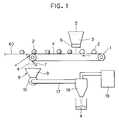
- a powder collecting and transporting device according to one embodiment of the present invention will be described with reference to Figs. 1 through 4.
- the powder collecting and transporting device is operated to collect powder used in a powder sprinkling system.
- the powder sprinkling system includes a conveyer belt 1 for transporting food 2 and a sprinkler 3 for sprinkling powder onto the food 2.
- the food 2 is made in a precedent process and is then put on the conveyer belt 1.
- the typical example of the food 2 is of a sticky material such as a dough of bread, rice cake, dough of noodle and confectionery, rice ball, fish paste, etc.
- the conveyer belt 1 is of an endless belt having a sufficient width.
- the sprinkler 3 is disposed above the conveyer belt 1 and is spaced away from the conveyer 1 by a space enabling food to pass between the sprinkler 3 and the conveyer belt 1.
- the sprinkler 3 includes a hopper 5 filled with powder 4 and a sprinkle portion 6 provided below the hopper 5.
- the sprinkler 3 per se is well known in the art.
- the sprinkle portion 6 should be changeable for adjusting sprinkling width and powder sprinkling amount.
- the powder 4 can be any powder according to type, objective, and use of the food dough 2, Examples of the powder is selected from flour, chocolate powder, sesame seeds, salt, crushed nuts, and bread crumbs.
- Another conveyer belt 40 is disposed downstream of the conveyer belt 1, so that the food can be transferred from the conveyer belt 1 to the conveyer belt 40.
- a fine gap is provided between the conveyer belts 1 and 40 so as to prevent the powder 4 on the conveyer belt 1 from being transferred to the conveyer belt 40.
- a scraper 7 is provided at a downstream end of the conveyer 1. A top end of the scraper 7 contacts the surface of the conveyer belt 1 to scrape off the powder 4 clinging to the conveyer 1.
- the powder collecting and transporting device includes a container 8 provided below the scraper 7 for collecting the powder 4.
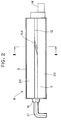
- the container 8 includes a hopper 9, a cylindrical frame 10 connected to the hopper 9, and a suction pipe 11 housed in the cylindrical frame 10.
- the hopper 9 has a funnel shape, that is, the cross-sectional area of upper portion is larger than the lower portion.
- the hopper 9 has an upper opening with a width and length long enough for receiving the powder 4 fall off the conveyer belt 1.
- the hopper 9 has a bottom discharge opening 12 having a rectangular shape with a length the same as the length of the hopper 9 and with a width smaller than the width of the upper opening.
- the cylindrical frame 10 connects to the bottom discharge opening 12 of the hopper 9.
- the cylindrical frame 10 has a circular shape in cross-section and extends to a length same as the length of the hopper 9.
- An opening 13 is formed on the upper side of the cylindrical frame 10 so that the opening 13 is fluidly connected to the bottom discharge opening 12 of the hopper 9.
- the suction pipe 11 has a cylindrical shape with a length approximately the same as that to the cylindrical frame 10.
- the suction pipe 11 is housed in the cylindrical frame 10 and is rotatable about its axis in the cylindrical frame 10.
- a motor 14 is provided at one end of the cylindrical frame 10.
- a power transmission mechanism is provided between the motor 14 and the suction pipe 11.
- a drive gear (not shown) is mounted on a motor shaft (not shown), and a driven gear(not shown) is mounted on one end of the suction pipe 11 and meshedly engaged with the drive gear.
- a slit-shaped suction opening 15 is formed in the pipe 11 so as to extend in the lengthwise direction of the suction pipe 11 while spiraling the periphery of the pipe 11 by about 360 degrees, i.e., one spiral pitch with respect to the length of the suction pipe 11.
- a portion of the opening 15 is exposed to the discharge opening 12 regardless of the rotation of the suction pipe 11 so as to provide a suction port 15A through which the powder in the hopper 9 can be introduced into the suction pipe 11.
- the suction port 15A is defined by an intersection between the discharge opening 12 and the spiral opening 15.
- a cover 16 is detachably provided on another end of the cylindrical frame 10 while allowing the rotation of the suction pipe 11.
- a transport pipe 17 is detachably attached to the cover 16 and is in fluid communication with the pipe 11.
- the transport pipe 17 has an inner diameter equal to an inner diameter of the suction pipe 11 so as to smoothen the flow of the powders.
- the transport pipe 17 has another end connected to a cyclone 18 for separation and recycling of the powder 4.
- a suction device 19 is also connected to the cyclone 18.
- the size of the spiral opening 15 is designed according to the cross-sectional area of the transport pipe 17 such that the suction port 15A exposing to the bottom discharge opening 12 has an area smaller than or equal to a cross-sectional area of the transport pipe 17.
- the size of the spiral opening 15 can be determined as desired according to properties of the power 4 and the performance of the suction device 19.
- a pair of seal boards 20 are attached to the major surfaces of the hopper 9 for hermetically sealing an edge of the bottom discharge opening 12 of the hopper 9 with the outer peripheral surface of the suction pipe 11.
- Each lower edge of the seal board 20 is in sliding contact with the outer peripheral surface of the pipe 11 when the latter is rotated about its axis.
- the seal boards 20 are detachable from the hopper 9.
- the powder 4 on the conveyer belt 1 is scraped off by the scraper 7 so that it falls off at the end of the conveyer belt 1 into the hopper 9.
- the powder 4 collected in the hopper 9 is sucked into the suction pipe 11 through the suction port 15A.
- the powder 4 is then transported through the transport pipe 17 to the cyclone 18 where it is separated and collected.
- the opening 15 is formed in the spiral shape, the suction port 15A moves constantly along a longitudinal direction of the discharge opening 12 in accordance with the rotation of the pipe 11. Therefore, the powder 14 can be evenly sucked along the length of the hopper 9.
- the suction port 15A is formed to a size equal to or smaller than the cross-sectional area of the transport pipe 17, the amount of the powder 4 sucked into the transport pipe 17 through the suction port 15A is proportional to the suction efficiency of the transport pipe 17. Therefore, no powder 4 remains in the transport pipe 17 and the like. In this way, the moving suction port 15A with this predetermined size can evenly and completely suck the powder 4 in the hopper 9 regardless of the length of the hopper 9.
- the opening 15 of the suction pipe is a spiral slit
- the suction port 15A moves constantly in a lengthwise direction along the entire bottom discharge opening 12 in accordance with the rotation of the suction pipe 11. Therefore, powder in the hopper 9 can be sucked constantly in a fixed direction, and the powder even in a large-sized long hopper can be sucked and transported evenly and completely. Thus, highly effective suction can be performed. The powder is less likely to clog up, and can be easily cleaned up.
- the size of the suction port 15A moving in accordance with the pipe rotation is relatively small, the compact suction device 19 is available. Therefore, the suction device 19 can be inexpensively manufactured in a compact size. Moreover, the power of suction can be controlled easily by changing the size of the suction opening. In this way, the powder can be effectively transferred to the cyclone 18.
- Fig. 5 shows a modification to the suction pipe.
- the slit opening 15 is of a continuous slit shape, and a part of the slit functions as the suction port 15A.
- a plurality of suction ports 15B are arrayed spirally in a suction pipe 11B.
- Each suction port 15B is provided by a bore having area smaller than or equal to the cross-sectional inner area of the transport pipe 17.
- the pipe 11B is rotated continuously or discontinuously so that at least one bore 15B can be in fluid communication with the discharge opening 12.
- the suction opening is formed with the spiral continuous slit 15, or the suction opening is formed with a plurality of bores 15B.
- the suction opening can be formed in any shape as long as it is able to suck the powder in the hopper evenly in accordance with the rotation of the pipe.
- the suction openings 15B can be arranged at random rather than in a spiral array and still be capable of evenly sucking the bottom opening 12 of the hopper 9.
- the suction portion can be limited to a specific area, or intended sucking order can be provided.
- the spiral line is making one round along the longitudinal axis of the suction pipe 11 or 11B.
- This arrangement is advantageous in continuous suction operation in accordance with the rotation of the suction pipe.
- several ports 15B can be positioned offset from the spiral line. In the latter case, in a specific rotation angle of the suction pipe 11B, neither one of the suction port 15B is in fluid communication with the discharge opening 12. That is, the suction is performed intermittently.
- the pipe 11 or 11B can be rotatable in opposite directions about its axis. Also, instead of the rotational motion of the suction pipe 11 or 11B about their axes, linear movement of a pipe along its axis is conceivable so as to move the suction port along the discharge opening 12.
Landscapes
- Life Sciences & Earth Sciences (AREA)
- Engineering & Computer Science (AREA)
- Food Science & Technology (AREA)
- Filling Or Emptying Of Bunkers, Hoppers, And Tanks (AREA)
- Air Transport Of Granular Materials (AREA)
- Manufacturing And Processing Devices For Dough (AREA)
- Confectionery (AREA)
- Electrostatic Spraying Apparatus (AREA)
Applications Claiming Priority (3)
| Application Number | Priority Date | Filing Date | Title |
|---|---|---|---|
| JP58301/96 | 1996-02-20 | ||
| JP5830196 | 1996-02-20 | ||
| JP8058301A JP2958749B2 (ja) | 1996-02-20 | 1996-02-20 | 粉粒体の回収装置 |
Publications (3)
| Publication Number | Publication Date |
|---|---|
| EP0791294A2 true EP0791294A2 (de) | 1997-08-27 |
| EP0791294A3 EP0791294A3 (de) | 1998-06-03 |
| EP0791294B1 EP0791294B1 (de) | 2001-12-12 |
Family
ID=13080408
Family Applications (1)
| Application Number | Title | Priority Date | Filing Date |
|---|---|---|---|
| EP97300489A Expired - Lifetime EP0791294B1 (de) | 1996-02-20 | 1997-01-27 | Vorrichtung zur Sammlung und zum Fördern von Pulver |
Country Status (6)
| Country | Link |
|---|---|
| US (1) | US5927908A (de) |
| EP (1) | EP0791294B1 (de) |
| JP (1) | JP2958749B2 (de) |
| AT (1) | ATE210376T1 (de) |
| DE (1) | DE69708948T2 (de) |
| ES (1) | ES2168573T3 (de) |
Cited By (2)
| Publication number | Priority date | Publication date | Assignee | Title |
|---|---|---|---|---|
| WO2005032267A1 (en) * | 2003-10-03 | 2005-04-14 | Comas S.P.A. | Machine for decorating a food product, in particular a cake, with an ingredient in granular form |
| CN111727997A (zh) * | 2020-07-24 | 2020-10-02 | 怀宁县洪铺镇永和食品厂 | 一种用于在糕点表面撒芝麻的装置 |
Families Citing this family (15)
| Publication number | Priority date | Publication date | Assignee | Title |
|---|---|---|---|---|
| JP3262212B2 (ja) * | 1997-03-11 | 2002-03-04 | レオン自動機株式会社 | 粉体供給機への粉体補充方法及び装置並びに粉体供給機 |
| US6332739B1 (en) * | 1998-11-16 | 2001-12-25 | Rheon Automatic Machinery Co., Ltd. | Powder supply system and powder supplying unit used in the system |
| US7736681B2 (en) | 2005-05-02 | 2010-06-15 | Nestec S.A. | Method for applying solid edible particulates to an edible substrate |
| DE202009012319U1 (de) * | 2009-09-09 | 2011-01-20 | SKS Sondermaschinen- und Fördertechnikvertriebs-GmbH | Vorrichtung zum Belegen zumindest eines Abschnitts eines Lebensmittels |
| DE202011103988U1 (de) * | 2011-08-03 | 2012-11-15 | Neuenkirchener Maschinenfabrik Emil Kemper Gmbh | Teigbearbeitungsvorrichtung |
| US9480372B1 (en) * | 2012-04-25 | 2016-11-01 | Kyle Taylor | Portable towelette dispenser |
| US9435939B2 (en) | 2012-08-02 | 2016-09-06 | Apple Inc. | Displays with coherent fiber bundles |
| CN105941783A (zh) * | 2016-06-29 | 2016-09-21 | 台州市宝刚机械有限公司 | 一体式糖块成型机 |
| JP6705713B2 (ja) * | 2016-07-20 | 2020-06-03 | 大和製罐株式会社 | カッティング装置 |
| JP6820712B2 (ja) * | 2016-10-13 | 2021-01-27 | 株式会社紀文食品 | 練り材料成型機 |
| WO2018201231A1 (en) * | 2017-05-02 | 2018-11-08 | Ibl Solutions Ltd | Conveyor belt cleaning apparatus |
| CN110100858B (zh) * | 2019-05-31 | 2021-02-09 | 海安爵珈机械科技有限公司 | 一种芝麻面球制作装置 |
| CN110510546B (zh) * | 2019-08-22 | 2021-05-11 | 浙江金瑞薄膜材料有限公司 | 预涂膜辅料机器人送料投料系统 |
| EP4262401A1 (de) * | 2020-12-21 | 2023-10-25 | Burford Corp. | System und verfahren zum aufbringen von garnierungen auf ein produkt |
| CN114247332A (zh) * | 2021-12-21 | 2022-03-29 | 南通市白龙有机肥科技有限公司 | 一种有机肥料生产集取装置 |
Family Cites Families (6)
| Publication number | Priority date | Publication date | Assignee | Title |
|---|---|---|---|---|
| US2827928A (en) * | 1954-10-11 | 1958-03-25 | Dole Eng Co James | Filling apparatus |
| US3182867A (en) * | 1963-11-18 | 1965-05-11 | Walker Mfg Co | Dispensing mechanism |
| GB1094112A (en) * | 1964-10-14 | 1967-12-06 | Tills Engineering Co Ltd | Transporting and dispensing installation for granular and pulverulent material |
| US3350141A (en) * | 1966-08-22 | 1967-10-31 | Acf Ind Inc | Pneumatic outlet for unloading particulate materials |
| US3717752A (en) * | 1971-06-24 | 1973-02-20 | W Warning | Particle spraying device |
| DE3203887A1 (de) * | 1981-02-09 | 1982-10-14 | Rogers Corp., 06263 Rogers, Conn. | Schaumstoffbeschichtete speiserolle |
-
1996
- 1996-02-20 JP JP8058301A patent/JP2958749B2/ja not_active Expired - Fee Related
-
1997
- 1997-01-27 DE DE69708948T patent/DE69708948T2/de not_active Expired - Lifetime
- 1997-01-27 AT AT97300489T patent/ATE210376T1/de not_active IP Right Cessation
- 1997-01-27 ES ES97300489T patent/ES2168573T3/es not_active Expired - Lifetime
- 1997-01-27 EP EP97300489A patent/EP0791294B1/de not_active Expired - Lifetime
- 1997-01-28 US US08/789,128 patent/US5927908A/en not_active Expired - Lifetime
Cited By (2)
| Publication number | Priority date | Publication date | Assignee | Title |
|---|---|---|---|---|
| WO2005032267A1 (en) * | 2003-10-03 | 2005-04-14 | Comas S.P.A. | Machine for decorating a food product, in particular a cake, with an ingredient in granular form |
| CN111727997A (zh) * | 2020-07-24 | 2020-10-02 | 怀宁县洪铺镇永和食品厂 | 一种用于在糕点表面撒芝麻的装置 |
Also Published As
| Publication number | Publication date |
|---|---|
| JP2958749B2 (ja) | 1999-10-06 |
| DE69708948T2 (de) | 2002-04-25 |
| JPH09224545A (ja) | 1997-09-02 |
| EP0791294A3 (de) | 1998-06-03 |
| EP0791294B1 (de) | 2001-12-12 |
| DE69708948D1 (de) | 2002-01-24 |
| ES2168573T3 (es) | 2002-06-16 |
| ATE210376T1 (de) | 2001-12-15 |
| US5927908A (en) | 1999-07-27 |
Similar Documents
| Publication | Publication Date | Title |
|---|---|---|
| EP0791294B1 (de) | Vorrichtung zur Sammlung und zum Fördern von Pulver | |
| EP0411174A2 (de) | Verteilungsvorrichtung zum Beschichten von Nahrungsmitteln | |
| CA2754198C (en) | Variable diameter, variable pitch auger with material scraper and breaker bar | |
| EP0411176A1 (de) | Kontrollvorrichtung zum Beschichten von Nahrungsmitteln | |
| JP5688094B2 (ja) | 共に混合された様々な流動性の材料を分離する装置 | |
| CA2068530A1 (en) | Apparatus and method for dispensing a cooked food product | |
| US20180228171A1 (en) | Apparatus for applying particulate matter to a substrate | |
| US5188262A (en) | Apparatus for dispensing moist powder materials | |
| CN106184904B (zh) | 用于散装物的装入设备 | |
| WO1991007883A1 (en) | An apparatus for hollowing root vegetables | |
| CN220476751U (zh) | 一种饼干粉料自动撒粉机 | |
| US11974593B2 (en) | System for processing foodstuff | |
| US6344227B1 (en) | Dough feeder wiper and method of use | |
| US12404116B2 (en) | Method and device for collecting litter or scrapings | |
| JPS6348495B2 (de) | ||
| EP1226763B1 (de) | Verfahren und Vorrichtung zur Beschichtung von Nahrungsmitteln mit partikelförmigem Material | |
| US3161441A (en) | Apparatus for cleaning and/or clearing the boot of an endless conveyor or the like | |
| CN215302643U (zh) | 煎饼果子制作机 | |
| CN210630538U (zh) | 一种糕点生产用自动撒粉装置 | |
| JPS6211439Y2 (de) | ||
| EP0959026A1 (de) | Verfahren und Vorrichtung zum Sammeln und Entladen von relativ leichtem Material | |
| CN214778881U (zh) | 一种螺旋上糠机 | |
| KR100913195B1 (ko) | 떡 고물 입힘 장치 | |
| CN212468340U (zh) | 一种有机肥加工用方便投料的蘑菇包破碎机 | |
| EP1042959A1 (de) | Nahrungsmittel bestehend aus dem Knochen von Kalamar, Verfahren und Vorrichtung zum Durchführen dieses Produkts |
Legal Events
| Date | Code | Title | Description |
|---|---|---|---|
| PUAI | Public reference made under article 153(3) epc to a published international application that has entered the european phase |
Free format text: ORIGINAL CODE: 0009012 |
|
| AK | Designated contracting states |
Kind code of ref document: A2 Designated state(s): AT BE CH DE ES FR GB IT LI NL SE |
|
| PUAL | Search report despatched |
Free format text: ORIGINAL CODE: 0009013 |
|
| AK | Designated contracting states |
Kind code of ref document: A3 Designated state(s): AT BE CH DE ES FR GB IT LI NL SE |
|
| 17P | Request for examination filed |
Effective date: 19981009 |
|
| GRAG | Despatch of communication of intention to grant |
Free format text: ORIGINAL CODE: EPIDOS AGRA |
|
| 17Q | First examination report despatched |
Effective date: 20010306 |
|
| GRAG | Despatch of communication of intention to grant |
Free format text: ORIGINAL CODE: EPIDOS AGRA |
|
| GRAH | Despatch of communication of intention to grant a patent |
Free format text: ORIGINAL CODE: EPIDOS IGRA |
|
| GRAH | Despatch of communication of intention to grant a patent |
Free format text: ORIGINAL CODE: EPIDOS IGRA |
|
| GRAA | (expected) grant |
Free format text: ORIGINAL CODE: 0009210 |
|
| AK | Designated contracting states |
Kind code of ref document: B1 Designated state(s): AT BE CH DE ES FR GB IT LI NL SE |
|
| REF | Corresponds to: |
Ref document number: 210376 Country of ref document: AT Date of ref document: 20011215 Kind code of ref document: T |
|
| REG | Reference to a national code |
Ref country code: CH Ref legal event code: EP |
|
| REG | Reference to a national code |
Ref country code: GB Ref legal event code: IF02 |
|
| REG | Reference to a national code |
Ref country code: CH Ref legal event code: NV Representative=s name: ISLER & PEDRAZZINI AG |
|
| REF | Corresponds to: |
Ref document number: 69708948 Country of ref document: DE Date of ref document: 20020124 |
|
| REG | Reference to a national code |
Ref country code: ES Ref legal event code: FG2A Ref document number: 2168573 Country of ref document: ES Kind code of ref document: T3 |
|
| PLBE | No opposition filed within time limit |
Free format text: ORIGINAL CODE: 0009261 |
|
| STAA | Information on the status of an ep patent application or granted ep patent |
Free format text: STATUS: NO OPPOSITION FILED WITHIN TIME LIMIT |
|
| 26N | No opposition filed | ||
| REG | Reference to a national code |
Ref country code: CH Ref legal event code: PCAR Free format text: ISLER & PEDRAZZINI AG;POSTFACH 1772;8027 ZUERICH (CH) |
|
| PGFP | Annual fee paid to national office [announced via postgrant information from national office to epo] |
Ref country code: ES Payment date: 20090203 Year of fee payment: 13 Ref country code: AT Payment date: 20090113 Year of fee payment: 13 |
|
| PGFP | Annual fee paid to national office [announced via postgrant information from national office to epo] |
Ref country code: GB Payment date: 20090121 Year of fee payment: 13 Ref country code: CH Payment date: 20090126 Year of fee payment: 13 |
|
| PGFP | Annual fee paid to national office [announced via postgrant information from national office to epo] |
Ref country code: BE Payment date: 20090119 Year of fee payment: 13 |
|
| PGFP | Annual fee paid to national office [announced via postgrant information from national office to epo] |
Ref country code: SE Payment date: 20090108 Year of fee payment: 13 |
|
| PGFP | Annual fee paid to national office [announced via postgrant information from national office to epo] |
Ref country code: IT Payment date: 20100120 Year of fee payment: 14 Ref country code: FR Payment date: 20100208 Year of fee payment: 14 |
|
| PGFP | Annual fee paid to national office [announced via postgrant information from national office to epo] |
Ref country code: DE Payment date: 20100121 Year of fee payment: 14 |
|
| BERE | Be: lapsed |
Owner name: *RHEON AUTOMATIC MACHINERY CO. LTD Effective date: 20100131 |
|
| REG | Reference to a national code |
Ref country code: CH Ref legal event code: PL |
|
| GBPC | Gb: european patent ceased through non-payment of renewal fee |
Effective date: 20100127 |
|
| EUG | Se: european patent has lapsed | ||
| PG25 | Lapsed in a contracting state [announced via postgrant information from national office to epo] |
Ref country code: LI Free format text: LAPSE BECAUSE OF NON-PAYMENT OF DUE FEES Effective date: 20100131 Ref country code: CH Free format text: LAPSE BECAUSE OF NON-PAYMENT OF DUE FEES Effective date: 20100131 |
|
| PG25 | Lapsed in a contracting state [announced via postgrant information from national office to epo] |
Ref country code: AT Free format text: LAPSE BECAUSE OF NON-PAYMENT OF DUE FEES Effective date: 20100127 |
|
| PG25 | Lapsed in a contracting state [announced via postgrant information from national office to epo] |
Ref country code: GB Free format text: LAPSE BECAUSE OF NON-PAYMENT OF DUE FEES Effective date: 20100127 |
|
| PG25 | Lapsed in a contracting state [announced via postgrant information from national office to epo] |
Ref country code: BE Free format text: LAPSE BECAUSE OF NON-PAYMENT OF DUE FEES Effective date: 20100131 |
|
| REG | Reference to a national code |
Ref country code: ES Ref legal event code: FD2A Effective date: 20110307 |
|
| PG25 | Lapsed in a contracting state [announced via postgrant information from national office to epo] |
Ref country code: ES Free format text: LAPSE BECAUSE OF NON-PAYMENT OF DUE FEES Effective date: 20110304 |
|
| REG | Reference to a national code |
Ref country code: NL Ref legal event code: V1 Effective date: 20110801 |
|
| PG25 | Lapsed in a contracting state [announced via postgrant information from national office to epo] |
Ref country code: ES Free format text: LAPSE BECAUSE OF NON-PAYMENT OF DUE FEES Effective date: 20100128 |
|
| REG | Reference to a national code |
Ref country code: FR Ref legal event code: ST Effective date: 20110930 |
|
| PG25 | Lapsed in a contracting state [announced via postgrant information from national office to epo] |
Ref country code: FR Free format text: LAPSE BECAUSE OF NON-PAYMENT OF DUE FEES Effective date: 20110131 |
|
| REG | Reference to a national code |
Ref country code: DE Ref legal event code: R119 Ref document number: 69708948 Country of ref document: DE Effective date: 20110802 |
|
| PG25 | Lapsed in a contracting state [announced via postgrant information from national office to epo] |
Ref country code: IT Free format text: LAPSE BECAUSE OF NON-PAYMENT OF DUE FEES Effective date: 20110127 Ref country code: NL Free format text: LAPSE BECAUSE OF NON-PAYMENT OF DUE FEES Effective date: 20110801 |
|
| PG25 | Lapsed in a contracting state [announced via postgrant information from national office to epo] |
Ref country code: SE Free format text: LAPSE BECAUSE OF NON-PAYMENT OF DUE FEES Effective date: 20100128 |
|
| PG25 | Lapsed in a contracting state [announced via postgrant information from national office to epo] |
Ref country code: DE Free format text: LAPSE BECAUSE OF NON-PAYMENT OF DUE FEES Effective date: 20110802 |
|
| PGFP | Annual fee paid to national office [announced via postgrant information from national office to epo] |
Ref country code: NL Payment date: 20100131 Year of fee payment: 14 |