EP0791368A2 - Dialysator - Google Patents
Dialysator Download PDFInfo
- Publication number
- EP0791368A2 EP0791368A2 EP97102296A EP97102296A EP0791368A2 EP 0791368 A2 EP0791368 A2 EP 0791368A2 EP 97102296 A EP97102296 A EP 97102296A EP 97102296 A EP97102296 A EP 97102296A EP 0791368 A2 EP0791368 A2 EP 0791368A2
- Authority
- EP
- European Patent Office
- Prior art keywords
- module
- capillaries
- open
- membrane
- dialyzer
- Prior art date
- Legal status (The legal status is an assumption and is not a legal conclusion. Google has not performed a legal analysis and makes no representation as to the accuracy of the status listed.)
- Granted
Links
- 239000012528 membrane Substances 0.000 claims abstract description 29
- 239000007788 liquid Substances 0.000 claims abstract description 13
- 238000011146 sterile filtration Methods 0.000 claims abstract description 5
- 150000001875 compounds Chemical class 0.000 claims description 17
- 238000000034 method Methods 0.000 claims description 9
- 238000005266 casting Methods 0.000 claims description 8
- 238000004382 potting Methods 0.000 claims description 7
- 238000007789 sealing Methods 0.000 claims description 7
- 238000010790 dilution Methods 0.000 claims description 6
- 239000012895 dilution Substances 0.000 claims description 6
- 238000005192 partition Methods 0.000 claims description 4
- 239000008280 blood Substances 0.000 description 14
- 210000004369 blood Anatomy 0.000 description 14
- 238000012864 cross contamination Methods 0.000 description 4
- XRWSZZJLZRKHHD-WVWIJVSJSA-N asunaprevir Chemical compound O=C([C@@H]1C[C@H](CN1C(=O)[C@@H](NC(=O)OC(C)(C)C)C(C)(C)C)OC1=NC=C(C2=CC=C(Cl)C=C21)OC)N[C@]1(C(=O)NS(=O)(=O)C2CC2)C[C@H]1C=C XRWSZZJLZRKHHD-WVWIJVSJSA-N 0.000 description 3
- 229940125961 compound 24 Drugs 0.000 description 3
- 238000011109 contamination Methods 0.000 description 3
- YSUIQYOGTINQIN-UZFYAQMZSA-N 2-amino-9-[(1S,6R,8R,9S,10R,15R,17R,18R)-8-(6-aminopurin-9-yl)-9,18-difluoro-3,12-dihydroxy-3,12-bis(sulfanylidene)-2,4,7,11,13,16-hexaoxa-3lambda5,12lambda5-diphosphatricyclo[13.2.1.06,10]octadecan-17-yl]-1H-purin-6-one Chemical compound NC1=NC2=C(N=CN2[C@@H]2O[C@@H]3COP(S)(=O)O[C@@H]4[C@@H](COP(S)(=O)O[C@@H]2[C@@H]3F)O[C@H]([C@H]4F)N2C=NC3=C2N=CN=C3N)C(=O)N1 YSUIQYOGTINQIN-UZFYAQMZSA-N 0.000 description 2
- 238000010276 construction Methods 0.000 description 2
- 239000012530 fluid Substances 0.000 description 2
- 238000001631 haemodialysis Methods 0.000 description 2
- 230000000322 hemodialysis Effects 0.000 description 2
- 238000002615 hemofiltration Methods 0.000 description 2
- 238000002360 preparation method Methods 0.000 description 2
- 238000004659 sterilization and disinfection Methods 0.000 description 2
- 239000012141 concentrate Substances 0.000 description 1
- 238000010586 diagram Methods 0.000 description 1
- 239000000385 dialysis solution Substances 0.000 description 1
- 238000009792 diffusion process Methods 0.000 description 1
- 239000002158 endotoxin Substances 0.000 description 1
- 238000001914 filtration Methods 0.000 description 1
- 230000002209 hydrophobic effect Effects 0.000 description 1
- 238000003860 storage Methods 0.000 description 1
- 238000006467 substitution reaction Methods 0.000 description 1
- 239000000725 suspension Substances 0.000 description 1
- 238000009423 ventilation Methods 0.000 description 1
Images

Classifications
-
- B—PERFORMING OPERATIONS; TRANSPORTING
- B01—PHYSICAL OR CHEMICAL PROCESSES OR APPARATUS IN GENERAL
- B01D—SEPARATION
- B01D61/00—Processes of separation using semi-permeable membranes, e.g. dialysis, osmosis or ultrafiltration; Apparatus, accessories or auxiliary operations specially adapted therefor
- B01D61/58—Multistep processes
-
- A—HUMAN NECESSITIES
- A61—MEDICAL OR VETERINARY SCIENCE; HYGIENE
- A61M—DEVICES FOR INTRODUCING MEDIA INTO, OR ONTO, THE BODY; DEVICES FOR TRANSDUCING BODY MEDIA OR FOR TAKING MEDIA FROM THE BODY; DEVICES FOR PRODUCING OR ENDING SLEEP OR STUPOR
- A61M1/00—Suction or pumping devices for medical purposes; Devices for carrying-off, for treatment of, or for carrying-over, body-liquids; Drainage systems
- A61M1/14—Dialysis systems; Artificial kidneys; Blood oxygenators ; Reciprocating systems for treatment of body fluids, e.g. single needle systems for hemofiltration or pheresis
- A61M1/16—Dialysis systems; Artificial kidneys; Blood oxygenators ; Reciprocating systems for treatment of body fluids, e.g. single needle systems for hemofiltration or pheresis with membranes
-
- A—HUMAN NECESSITIES
- A61—MEDICAL OR VETERINARY SCIENCE; HYGIENE
- A61M—DEVICES FOR INTRODUCING MEDIA INTO, OR ONTO, THE BODY; DEVICES FOR TRANSDUCING BODY MEDIA OR FOR TAKING MEDIA FROM THE BODY; DEVICES FOR PRODUCING OR ENDING SLEEP OR STUPOR
- A61M1/00—Suction or pumping devices for medical purposes; Devices for carrying-off, for treatment of, or for carrying-over, body-liquids; Drainage systems
- A61M1/14—Dialysis systems; Artificial kidneys; Blood oxygenators ; Reciprocating systems for treatment of body fluids, e.g. single needle systems for hemofiltration or pheresis
- A61M1/16—Dialysis systems; Artificial kidneys; Blood oxygenators ; Reciprocating systems for treatment of body fluids, e.g. single needle systems for hemofiltration or pheresis with membranes
- A61M1/1654—Dialysates therefor
- A61M1/1656—Apparatus for preparing dialysates
- A61M1/1672—Apparatus for preparing dialysates using membrane filters, e.g. for sterilising the dialysate
-
- A—HUMAN NECESSITIES
- A61—MEDICAL OR VETERINARY SCIENCE; HYGIENE
- A61M—DEVICES FOR INTRODUCING MEDIA INTO, OR ONTO, THE BODY; DEVICES FOR TRANSDUCING BODY MEDIA OR FOR TAKING MEDIA FROM THE BODY; DEVICES FOR PRODUCING OR ENDING SLEEP OR STUPOR
- A61M1/00—Suction or pumping devices for medical purposes; Devices for carrying-off, for treatment of, or for carrying-over, body-liquids; Drainage systems
- A61M1/34—Filtering material out of the blood by passing it through a membrane, i.e. hemofiltration or diafiltration
- A61M1/342—Adding solutions to the blood, e.g. substitution solutions
- A61M1/3424—Substitution fluid path
- A61M1/3431—Substitution fluid path upstream of the filter
- A61M1/3434—Substitution fluid path upstream of the filter with pre-dilution and post-dilution
-
- A—HUMAN NECESSITIES
- A61—MEDICAL OR VETERINARY SCIENCE; HYGIENE
- A61M—DEVICES FOR INTRODUCING MEDIA INTO, OR ONTO, THE BODY; DEVICES FOR TRANSDUCING BODY MEDIA OR FOR TAKING MEDIA FROM THE BODY; DEVICES FOR PRODUCING OR ENDING SLEEP OR STUPOR
- A61M1/00—Suction or pumping devices for medical purposes; Devices for carrying-off, for treatment of, or for carrying-over, body-liquids; Drainage systems
- A61M1/34—Filtering material out of the blood by passing it through a membrane, i.e. hemofiltration or diafiltration
- A61M1/342—Adding solutions to the blood, e.g. substitution solutions
- A61M1/3424—Substitution fluid path
- A61M1/3437—Substitution fluid path downstream of the filter, e.g. post-dilution with filtrate
-
- A—HUMAN NECESSITIES
- A61—MEDICAL OR VETERINARY SCIENCE; HYGIENE
- A61M—DEVICES FOR INTRODUCING MEDIA INTO, OR ONTO, THE BODY; DEVICES FOR TRANSDUCING BODY MEDIA OR FOR TAKING MEDIA FROM THE BODY; DEVICES FOR PRODUCING OR ENDING SLEEP OR STUPOR
- A61M1/00—Suction or pumping devices for medical purposes; Devices for carrying-off, for treatment of, or for carrying-over, body-liquids; Drainage systems
- A61M1/34—Filtering material out of the blood by passing it through a membrane, i.e. hemofiltration or diafiltration
- A61M1/342—Adding solutions to the blood, e.g. substitution solutions
- A61M1/3455—Substitution fluids
- A61M1/3465—Substitution fluids using dialysate as substitution fluid
-
- B—PERFORMING OPERATIONS; TRANSPORTING
- B01—PHYSICAL OR CHEMICAL PROCESSES OR APPARATUS IN GENERAL
- B01D—SEPARATION
- B01D61/00—Processes of separation using semi-permeable membranes, e.g. dialysis, osmosis or ultrafiltration; Apparatus, accessories or auxiliary operations specially adapted therefor
- B01D61/24—Dialysis ; Membrane extraction
- B01D61/243—Dialysis
- B01D61/244—Dialysis comprising multiple dialysis steps
-
- B—PERFORMING OPERATIONS; TRANSPORTING
- B01—PHYSICAL OR CHEMICAL PROCESSES OR APPARATUS IN GENERAL
- B01D—SEPARATION
- B01D63/00—Apparatus in general for separation processes using semi-permeable membranes
- B01D63/02—Hollow fibre modules
- B01D63/04—Hollow fibre modules comprising multiple hollow fibre assemblies
-
- A—HUMAN NECESSITIES
- A61—MEDICAL OR VETERINARY SCIENCE; HYGIENE
- A61M—DEVICES FOR INTRODUCING MEDIA INTO, OR ONTO, THE BODY; DEVICES FOR TRANSDUCING BODY MEDIA OR FOR TAKING MEDIA FROM THE BODY; DEVICES FOR PRODUCING OR ENDING SLEEP OR STUPOR
- A61M1/00—Suction or pumping devices for medical purposes; Devices for carrying-off, for treatment of, or for carrying-over, body-liquids; Drainage systems
- A61M1/34—Filtering material out of the blood by passing it through a membrane, i.e. hemofiltration or diafiltration
- A61M1/3413—Diafiltration
Definitions
- the invention relates to a dialyzer, which is intended in particular for use in the hemodiafiltration process.
- Hemodiafiltration is a combination procedure in which hemodialysis and hemofiltration are carried out simultaneously. This procedure combines the advantages of convective mass transport in hemofiltration and that of the dialytic diffusion process.
- the substitution liquid substituted in the known on-line hemodiafiltration method.
- the patient's fluid balance is centrally controlled with the balancing chamber, taking into account all added and withdrawn fluids.
- no additional storage container for the substituate is required, since this is produced at the same time.
- the substituate is sterile filtered by a specially provided on-line hemodiafiltration filter, which is present in addition to the actual hemodiafiltration filter.
- the additionally provided on-line hemodiafiltration filter is not changed with every treatment.
- a separate anti-contamination chamber is therefore provided to reduce the risk of cross-contamination. Despite this measure, there is still a residual risk of cross-contamination.
- the object of the invention is to provide a dialyzer in which the aforementioned cross-contamination risk is eliminated as far as possible and, in addition, the construction and operation of the hemodiafiltration system are simplified.
- the dialyzer according to the present invention consists of two modules realized in one structural unit, the first module having a bundle of membrane capillaries and one inlet and one outlet for the liquid to be treated and one inlet and one outlet for the dialysate.
- the second module also includes a bundle of membrane capillaries for sterile filtration of the substituate and an inlet for the substituate.
- the dialyzer has a chamber in which the cleaned substituate can be combined with the liquid to be treated, ie the blood.
- the dialyzer according to the invention thus combines a conventional standard hemodialysis unit with a sterile filtration unit for the substituate which is necessary for on-line hemodiafiltration.
- the entire dialyzer is designed as a disposable part, so that disinfection of the module and consequent disinfection damage to the housing or the membrane or infusible residues are avoided.
- the cross contamination risk that existed in the previously known system has been eliminated.
- Another advantage is that a pre-leak test of the previously separately provided on-line filter for the Substitute is eliminated. This goes hand in hand with a shorter preparation time and, as a result, better availability. Compared to the known system explained at the beginning, in which repeated dead-end filtration was carried out, it is no longer possible to concentrate endotoxins.
- the entire dialyzer is designed as a disposable part, an uncontrolled period of use of the dialyzer beyond the recommendations is no longer possible. This prevents incorrect operation and eliminates all critical and time-related conditions.
- the hose system required to convey the substituate to be filtered sterile can now be constructed very simply.
- the anti-contamination chamber to be provided in the previous system can be omitted.
- the dialyzer is compatible with all hose systems and machines. Finally, by saving the additional on-line filter, a corresponding suspension and the associated space are saved, so that the overall system is constructed in a simpler and clearer manner.
- the dialyzer consists of an elongated housing which is closed at both ends by a cover.
- the two modules in the elongated housing are separated from each other by a partition.
- the membrane capillaries arranged in the modules in the longitudinal direction of the housing are each embedded in casting compounds which close the open ends of the elongated housing.
- the capillaries of the membrane capillary bundle in the first module can extend with their ends open at the end through the casting compounds.
- the capillaries of the membrane capillary bundle in the second module can extend with their first ends that are open at the end through the casting compound, while they with the opposite second ones open ends are embedded in the sealing compound and are closed by them.
- the first and second ends of the capillaries may extend through the potting compounds.
- the second ends can be closed, for example, by an appropriately adapted cover.
- the substituate can be sterile filtered through the membrane capillaries in the second module and combined with the liquid to be treated, ie the blood, through the first open ends of the membrane capillaries.
- the membrane capillaries arranged in the second module can open with their first open ends in a chamber formed between the sealing compound and the cover, that is to say the flange space, the cover being connected to the inlet for the liquid to be treated, that is to say the blood .
- This is the so-called pre-dilution.
- the membrane capillaries arranged in the second module can open with their first open end in a chamber formed between the sealing compound and the cover, that is to say a flange space, the cover being connected to the outlet for the liquid to be treated. In this case, post-dilution takes place.
- dialyzer according to the invention in an on-line hemodiafiltration process is particularly advantageous.
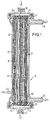
- the dialyzer 10 according to the embodiment shown in FIG. 1 comprises a cylindrical and elongated housing 12, which is closed at the end with covers 14 and 16.
- the elongated housing is divided into two modules 20 and 22 by a partition 18.
- the modules 20 and 22 are each delimited on the one hand by the partition and the outer wall of the housing 12 and on the other hand by the sealing compounds 24 and 26 closing at the end of the housing 12.
- the module 20 includes, in a manner known per se, a microcapillary bundle with microcapillaries 28 which, as shown in FIG. 1, run along the elongated housing 12 and are embedded in the casting compounds 24 and 26 in such a way that their open ends each lie in between the potting compounds 24 and 26 and the lids 14 and 16 formed cavities or chambers 30, 32 open.
- the module 20 has an inlet 34 and an outlet 36 for the dialysate in the manner shown in FIG. 1.
- An inlet 38 for the blood is formed centrally on the lid 14, while an outlet 40 for the blood is formed centrally on the lid 16.
- the module 22 also has a capillary bundle with membrane capillaries 42.
- These membrane capillaries 42 also extend elongated to the cylindrical housing 12. They are embedded at one end in the casting compound 26 in such a way that they are closed by them. The opposite end of the membrane capillaries 42 is embedded in the sealing compound 24, but with the ends to the chamber 30 between the potting compound 24 and the lid 14 open.
- the blood to be cleaned enters the inlet 38 and is combined in the chamber 30 with a sterile-filtered substituate.
- the blood mixed with the substituate enters the membrane capillaries 28 and passes through them to their opposite end, which opens into the chamber 32.
- the purified blood exits via the chamber 32 and the outlet 40.
- the dialysate is introduced via the corresponding inlet 34 and runs in countercurrent to the blood to be purified until it emerges from the outlet 36 at the opposite end of the module 20.
- the substituate to be treated enters in the direction of the arrow via an inlet 44.
- the substituate to be cleaned is sterile filtered through the membrane capillaries 42.
- the sterile-filtered substituate exits into the chamber 30 at the open end of the membrane capillaries, as previously described, and is mixed there with the blood to be treated.
- the arrows shown in FIG. 1 indicate the flow direction of the liquid flows.
- a pre-dilution is implemented in the embodiment according to FIG. 1, in which the substituate is combined with the blood that is still to be cleaned.
- FIG. 2 largely corresponds to that of FIG. 1. Therefore, the same parts are also provided with the same reference numerals.
- the overall structure of the housing 12 and the cover 14 or 16, as well as the module 20 corresponds to the previously described embodiment.
- the exemplary embodiment differs in the construction of the second module 22.
- the open end of the capillaries opens into the chamber 32, which is formed between the casting compound 26 and the cover 16.
- the opposite end of the membrane capillaries is in the sealing compound 24 embedded in such a way that the ends are closed.
- the sealing compound 24 embedded in such a way that the ends are closed.
- the inlet 44 for the substituate to be cleaned is arranged on the opposite side of the elongated housing 12, so that the substituate to be cleaned flows in this embodiment as far as possible over the entire length of the housing 12 (cf. Arrow direction) and can be cleaned in this way by sterile filtration using the membrane walls.
- the purified blood is combined with the substituate in the chamber 32, so that post-dilution is achieved here.
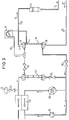
- FIG. 3 shows the structure of an on-line hemodiafiltration system.
- the blood drawn from the patient is fed via a line 50 to the inlet 38 of the dialyzer 10.
- the cleaned blood is passed in the direction of arrow a via the outlet 40 and the line 52 into a drip chamber 54, from where it is returned to the patient.
- the substituate is fed through a line 56 and a substituate pump 58 into the inlet 44 of the dialyzer 10.
- the part of the on-line hemodiafiltration system according to FIG. 3 which relates to the preparation of the dialysate corresponds to the already known systems.
- This part thus comprises a dialysis fluid filter 60, a dialyzer valve 62, a bypass valve 64, a valve 66, a dialysate flow pump 68, a UF pump 70, a balancing chamber 72, a hydrophobic filter 74 and a ventilation valve 76.
- the on-line hemodiafiltration system according to FIG. 3 is significantly simplified due to the use of the dialyzer 10 according to the invention compared to the previously known method, since a separate filter for the substituate and an additional anti-contamination chamber arranged downstream of it are no longer necessary.
Landscapes
- Health & Medical Sciences (AREA)
- Heart & Thoracic Surgery (AREA)
- Engineering & Computer Science (AREA)
- Life Sciences & Earth Sciences (AREA)
- Animal Behavior & Ethology (AREA)
- Veterinary Medicine (AREA)
- Public Health (AREA)
- General Health & Medical Sciences (AREA)
- Vascular Medicine (AREA)
- Anesthesiology (AREA)
- Biomedical Technology (AREA)
- Hematology (AREA)
- Urology & Nephrology (AREA)
- Chemical & Material Sciences (AREA)
- Chemical Kinetics & Catalysis (AREA)
- Water Supply & Treatment (AREA)
- Emergency Medicine (AREA)
- External Artificial Organs (AREA)
Abstract
Description
- Die Erfindung betrifft einen Dialysator, der insbesondere zum Einsatz beim Hämodiafiltrations-Verfahren bestimmt ist.
- Die Hämodiafiltration ist ein Kombinationsverfahren, bei dem man eine Hämodialyse und Hämofiltration gleichzeitig durchführt. Dieses Verfahren verbindet die Vorteile des konvektiven Massentransport bei der Hämofiltration und den des dialytischen Diffusionsprozesses. Bei dem bekannten On-Line Hämodiafiltrationsverfahren nutzt man zur Bilanzierung aus, daß auch die Substitutionflüssigkeit (Substituat) durch die Bilanzierungskammern direkt erfaßt wird. Das bedeutet, daß mit der Bilanzierungskammer der Flüssigkeitshaushalt des Patienten unter Beachtung aller zugesetzten und entzogenen Flüssigkeiten zentral gesteuert wird. Es wird bei einem On-Line Verfahren auch kein zusätzlicher Vorratsbehälter für das Substituat benötigt, da dieses zeitgleich hergestellt wird. Bei dem bekannten Verfahren wird das Substituat durch einen eigens vorgesehenen On-Line Hämodiafiltrations-Filter steril filtriert, der zusätzlich zu dem eigentlichen Hämodiafiltrations-Filter vorhanden ist. Der zusätzlich vorgesehene On-Line Hämodiafiltrationsfilter wird nicht bei jeder Behandlung gewechselt. Daher wird zur Verringerung des Kreuzkontaminationsrisikos eine eigene Antikontaminationskammer vorgesehen. Trotz dieser Maßnahme bleibt noch ein Restrisiko für eine Kreuzkontamination.
- Aufgabe der Erfindung ist es, einen Dialysator zu schaffen, bei dem das vorgenannte Kreuzkontaminationsrisiko möglichst ausgeschaltet wird und zusätzlich der Aufbau und die Bedienung des Hämodiafiltrationssystems vereinfacht werden.
- Erfindungsgemäß wird diese Aufgabe durch die Merkmale des Patentanspruchs 1 gelöst. Demnach besteht der Dialysator nach der vorliegenden Erfindung aus zwei in einer Baueinheit verwirklichten Modulen, wobei das erste Modul ein Bündel von Membrankapillaren und je einen Einlaß und einen Auslaß für die zu behandelnde Flüssigkeit und einen Einlaß und einen Auslaß für das Dialysat aufweist. Das zweite Modul umfaßt ebenfalls ein Bündel von Membrankapillaren zur Sterilfiltrierung von Substituat und einen Einlaß für das Substituat. Der Dialysator weist eine Kammer auf, in der das gereinigte Substituat mit der zu behandelnden Flüssigkeit, das heißt dem Blut, vereinigbar ist.
- Der erfindungsgemäße Dialysator vereinigt somit eine übliche Standard-Hämodialyseeinheit mit einer für die On-Line Hämodiafiltration notwendigen Sterilfiltrationseinheit für das Substituat. Der gesamte Dialysator ist als Wegwerfteil konzipiert, so daß eine Desinfektion des Moduls und dadurch bedingte Desinfektionsschädigungen beim Gehäuse oder der Membran oder infundierbare Rückstände vermieden werden. Insbesondere die Kreuzkontaminationsgefahr, die bei dem vorbekannten System bestand, ist beseitigt.
- Ein weiterer Vorteil besteht darin, daß eine Vorabdichtheitsprüfung des früher separat vorzusehenden On-Line Filters für das Substituat entfällt. Dies geht mit einer kürzeren Vorbereitungszeit und einer dadurch bedingten besseren Verfügbarkeit einher. Gegenüber dem eingangs erläuterten bekannten System, bei dem eine wiederholte Dead-End Filtration vorgenommen wurde, ist keine Aufkonzentration von Endotoxinen mehr möglich.
- Da der gesamte Dialysator als Wegwerfteil konzipiert ist, ist auch eine unkontrollierte, über die Empfehlungen hinausgehende Einsatzdauer des Dialysators nicht mehr möglich. Damit ist Fehlbedienungen vorgebeugt und es entfallen alle zeit- und zyklusbedingten kritischen Zustände. Das zur Förderung des steril zu filtrierenden Substituats benötigte Schlauchsystem kann nunmehr sehr einfach aufgebaut werden. Die im früheren System vorzusehende Antikontaminationskammer kann entfallen. Der Dialysator ist zu allen Schlauchsystemen und Maschinen kompatibel. Schließlich wird durch die Einsparung des zusätzlichen On-Line Filters eine entsprechende Aufhängung und der zugehörige Platz eingespart, so daß das Gesamtsystem einfacher und übersichtlicher aufgebaut ist.
- Gemäß einer vorteilhaften Ausgestaltung der Erfindung besteht der Dialysator aus einem langgestreckten Gehäuse, das an seinen beiden Enden jeweils durch Deckel verschlossen ist. Die beiden Module in dem langgestreckten Gehäuse werden durch eine Trennwand voneinander abgeteilt. Die in den Modulen in Gehäuselängsrichtung angeordneten Membrankapillaren sind jeweils in Vergußmassen eingebettet, die die offenen Enden des langgestreckten Gehäuses verschließen. Dabei können sich die Kapillaren des Membrankapillarbündels im ersten Modul mit ihren stirnseitig offenen Enden durch die Vergußmassen hindurch erstrecken. Die Kapillaren des Membrankapillarbündels im zweiten Modul können sich mit ihren ersten stirnseitig offenen Enden durch die Vergußmasse hindurch erstrecken, während sie mit den gegenüberliegenden zweiten stirnseitig offenen Enden in der Vergußmasse eingebettet und durch diese verschlossen sind. Alternativ dazu können sich die ersten und zweiten Enden der Kapillaren durch die Vergußmassen hindurch erstrecken. Die zweiten Enden können bei dieser Ausführungsform beispielsweise durch einen entsprechend angepaßten Deckel verschlossen werden. Durch diese Anordnungen kann im zweiten Modul das Substituat durch die Membrankapillaren steril filtriert werden und durch die ersten offenen Enden der Membrankapillaren mit der zu behandelnden Flüssigkeit, das heißt dem Blut, vereinigt werden.
- Dabei können die im zweiten Modul angeordneten Membrankapillaren mit ihren ersten offenen Enden in einer zwischen der Vergußmasse und dem Deckel gebildeten Kammer, das heißt dem Flanschraum, münden, wobei der Deckel mit dem Einlaß für die zu behandelnde Flüssigkeit, das heißt dem Blut, verbunden ist. Hier handelt es sich um die sogenannte pre-dilution.
- Andererseits können die im zweiten Modul angeordneten Membrankapillaren mit ihrem ersten offenen Ende in einer zwischen der Vergußmasse und dem Deckel gebildeten Kammer, das heißt Flanschraum, münden, wobei der Deckel mit dem Auslaß für die zu behandelnde Flüssigkeit verbunden ist. In diesem Fall erfolgt eine post-dilution.
- Besonders vorteilhaft ist die Verwendung des erfindungsgemäßen Dialysators in einem On-Line Hämodiafiltrationsverfahren.
- Weitere Einzelheiten und Vorteile der Erfindung werden anhand von in der Zeichnung dargestellten Ausführungsbeispielen näher erläutert. Es zeigen:
- Fig. 1:
- einen Längsschnitt durch eine erste Ausführungsform eines erfindungsgemäßen Dialysators,
- Fig. 2:
- einen Längsschnitt durch eine zweite Ausführungsform des erfindungsgemäßen Dialysators,
- Fig. 3:
- ein Systemschema einer On-Line Hämodiafiltration, in welcher der erfindungsgemäße Dialysator eingesetzt ist.
- Der Dialysator 10 gemäß der in Fig. 1 dargestellten Ausführungsform umfaßt ein zylindrisches und langgestrecktes Gehäuse 12, das endseitig mit Deckeln 14 und 16 verschlossen ist. Das langgestreckte Gehäuse ist über eine Trennwand 18 in zwei Module 20 und 22 unterteilt. Die Module 20 und 22 werden jeweils einerseits durch die Trennwand und die Außenwandung des Gehäuses 12 und andererseits durch das Gehäuse 12 endseitig verschließende Vergußmassen 24 und 26 begrenzt. Das Modul 20 beinhaltet in an sich bekannter Art und Weise ein Mikrokapillarbündel mit Mikrokapillaren 28, die, wie in Fig. 1 dargestellt, längs des langgestreckten Gehäuses 12 verlaufen und in den Vergußmassen 24 und 26 derart eingebettet sind, daß ihre offenen Enden jeweils in zwischen den Vergußmassen 24 und 26 und den Deckeln 14 und 16 gebildeten Hohlräumen oder Kammern 30, 32 münden. Das Modul 20 weist einen Einlaß 34 und einen Auslaß 36 für das Dialysat in der in Fig. 1 dargestellten Art und Weise auf. Ein Einlaß 38 für das Blut ist zentrisch am Deckel 14 ausgebildet, während ein Auslaß 40 für das Blut zentrisch am Deckel 16 ausgebildet ist.
- Auch das Modul 22 weist ein Kapillarbündel mit Membrankapillaren 42 auf. Diese Membrankapillaren 42 erstrecken sich ebenfalls langgestreckt zum zylindrischen Gehäuse 12. Sie sind mit einem Ende derart in die Vergußmasse 26 eingebettet, daß sie durch diese verschlossen sind. Das gegenüberliegende Ende der Membrankapillaren 42 ist in der Vergußmasse 24 eingebettet, jedoch mit den Enden zur Kammer 30 zwischen der Vergußmasse 24 und dem Deckel 14 hin offen.
- Bei dem in Fig. 1 dargestellten Dialysator tritt das zu reinigende Blut im Einlaß 38 ein und wird in der Kammer 30 mit sterilfiltriertem Substituat vereinigt. Das mit dem Substituat vermengte Blut tritt in die Membrankapillaren 28 ein und durchläuft diese bis zu deren gegenüberliegendem Ende, das in die Kammer 32 mündet. Über die Kammer 32 und den Auslaß 40 tritt das gereinigte Blut aus. Innerhalb des Moduls 20 wird das Dialysat über den entsprechenden Einlaß 34 eingeleitet und läuft im Gegenstrom zu dem zu reinigenden Blut, bis es am gegenüberliegenden Ende des Moduls 20 aus dem Auslaß 36 wieder austritt. Im Modul 22 tritt das zu behandelnde Substituat in Pfeilrichtung über einen Einlaß 44 ein. Innerhalb des Moduls 22 wird das zu reinigende Substituat über die Membrankapillaren 42 sterilfiltriert. Das sterilfiltrierte Substituat tritt am offenen Ende der Membrankapillaren, wie zuvor beschrieben, in die Kammer 30 aus und wird dort mit dem zu behandelnden Blut gemischt. Durch die in Fig. 1 gezeigten Pfeile wird jeweils die Strömungsrichtung der Flüssigkeitsströme angezeigt. Bei dem Ausführungsbeispiel gemäß Fig. 1, in welchem das Substituat mit dem einstömenden noch zu reinigenden Blut vereinigt wird, ist eine pre-dilution verwirklicht.
- Das Ausführungsbeispiel gemäß Fig. 2 entspricht weitgehend demjenigen gemäß Fig. 1. Daher sind gleiche Teile auch mit gleichen Bezugszeichen versehen. Insbesondere der Gesamtaufbau des Gehäuses 12 und der Deckel 14 bzw. 16, sowie des Moduls 20 entspricht dem zuvor beschriebenen Ausführungsbeispiel. Das Ausführungsbeispiel unterscheidet sich aber im Aufbau des zweiten Moduls 22. Hier mündet das offene Ende der Kapillaren in die Kammer 32, die zwischen der Vergußmasse 26 und dem Deckel 16 gebildet ist. Das gegenüberliegende Ende der Membrankapillaren ist in der Vergußmasse 24 derart eingebettet, daß die Enden verschlossen sind. Weiterhin ist im Unterschied zum Ausführungsbeispiel gemäß Fig. 1 der Einlaß 44 für das zu reinigende Substituat auf der gegenüberliegenden Seite des langgestreckten Gehäuses 12 angeordnet, so daß das zu reinigende Substituat auch in dieser Ausführungsform möglichst über die gesamte Länge des Gehäuses 12 fließt (vgl. Pfeilrichtung) und über diesen Weg durch Sterilfiltration mittels der Membranwände gereinigt werden kann. Bei diesem Ausführungsbeispiel wird in der Kammer 32 das gereinigte Blut mit dem Substituat vereinigt, so daß hier eine post-dilution verwirklicht ist.
- In Fig. 3 ist grundsätzlich der Aufbau eines On-Line Hämodiafiltrationssystems gezeigt. In Pfeilrichtung a wird das vom Patienten abgenommene Blut über eine Leitung 50 dem Einlaß 38 des Dialysators 10 zugeführt. Das gereinigte Blut wird in Pfeilrichtung a über den Auslaß 40 und die Leitung 52 in eine Tropfkammer 54 geleitet, von wo aus sie dem Patienten wieder zugeführt wird. Das Substituat wird über eine Leitung 56 und eine Substituatpumpe 58 in den Einlaß 44 des Dialysators 10 eingespeist. Der Teil des On-Line Hämodiafiltrationssystems gemäß Fig. 3, der die Aufbereitung des Dialysats betrifft, entspricht den bereits bekannten Systemen. So umfaßt dieser Teil ein Dialysierflüssigkeitsfilter 60, ein Dialysatorventil 62, ein Bypassventil 64, ein Ventil 66, eine Dialysatflußpumpe 68, eine UF-Pumpe 70, eine Bilanzkammer 72, ein Hydrophobfilter 74 und ein Belüftungsventil 76.
- Das On-Line Hämodiafiltrationssystem gemäß der Fig. 3 ist aufgrund des Einsatzes des erfindungsgemäßen Dialysators 10 gegenüber dem vorbekannten Verfahren deutlich vereinfacht, da hier ein gesonderter Filter für das Substituat und eine diesem nachgeordnete zusätzliche Antikontaminationskammer nicht mehr notwendig sind.
Claims (7)
- Dialysator bestehend aus zwei in einer Baueinheit verwirklichten Modulen, wobei das erste Modul ein Bündel von Membrankapillaren und je einen Einlaß und einen Auslaß für die zu behandelnde Flüssigkeit und einen Einlaß und einen Auslaß für das Dialysat aufweist, wobei das zweite Modul ebenfalls ein Bündel von Membrankapillaren zur Sterilfiltrierung von Substituat und einen Einlaß für das Substituat umfaßt und wobei der Dialysator eine Kammer aufweist, in der das gereinigte Substituat mit der zu behandelnden Flüssigkeit vereinigbar ist.
- Dialysator nach Anspruch 1, dadurch gekennzeichnet, daß er aus einem langgestreckten Gehäuse besteht, das an seinen beiden Enden jeweils durch Deckel verschlossen ist, daß die beiden Module in dem langgestreckten Gehäuse durch eine Trennwand voneinander abgeteilt sind, daß die in den Modulen in Gehäuselängsrichtung angeordneten Membrankapillaren jeweils in die die offenen Enden des langgestreckten Gehäuses verschließenden Vergußmassen eingebettet sind.
- Dialysator nach Anspruch 2, dadurch gekennzeichnet, daß sich die Kapillaren des Membrankapillarbündels im ersten Modul mit ihren beiden stirnseitig offenen Enden durch die Vergußmassen hindurch erstrecken und daß sich die Kapillaren des Membrankapillarbündels im zweiten Modul mit ihren ersten stirnseitig offenen Enden durch die Vergußmasse hindurch erstrecken, während sie mit den gegenüberliegenden zweiten stirnseitigen offenen Enden in der Vergußmasse eingebettet und durch diese verschlossen sind.
- Dialysator nach Anspruch 2, dadurch gekennzeichnet, daß sich die Kapillaren des Membrankapillarbündels im ersten Modul und im zweiten Modul mit ihren beiden stirnseitig offenen Enden durch die Vergußmasse hindurch erstrecken und daß die stirnseitig offenen Enden der Kapillaren des Membrankapillarbündels des zweiten Moduls auf einer Seite durch einen entsprechend aufgebauten Deckel verschlossen sind.
- Dialysator nach Anspruch 3 oder 4, dadurch gekennzeichnet, daß die im zweiten Modul angeordneten Membrankapillaren mit ihrem ersten offenen Ende in einer zwischen der Vergußmasse und dem Deckel gebildeten Kammer münden, wobei der Deckel mit dem Einlaß für die zu behandelnde Flüssigkeit verbunden ist (pre-dilution).
- Dialysator nach Anspruch 3 oder 4, dadurch gekennzeichnet, daß die im zweiten Modul angeordneten Membrankapillaren mit ihrem ersten offenen Ende in einer zwischen der Vergußmasse und dem Deckel gebildeten Kammer münden, wobei der Deckel mit dem Auslaß für die zu behandelnde Flüssigkeit verbunden ist (post-dilution).
- Verwendung eines Dialysators nach einem der vorangehenden Ansprüche in einem On-Line Hämodiafiltrationsverfahren.
Applications Claiming Priority (2)
| Application Number | Priority Date | Filing Date | Title |
|---|---|---|---|
| DE19607162 | 1996-02-26 | ||
| DE19607162A DE19607162C2 (de) | 1996-02-26 | 1996-02-26 | Verwendung eines Dialysators mit zwei Modulen zur Durchführung eines Verfahrens zum Filtrieren und sofortigen Verwenden von Substituatflüssigkeit in einer Hämodialfiltrationsvorrichtung |
Publications (3)
| Publication Number | Publication Date |
|---|---|
| EP0791368A2 true EP0791368A2 (de) | 1997-08-27 |
| EP0791368A3 EP0791368A3 (de) | 1998-01-14 |
| EP0791368B1 EP0791368B1 (de) | 2006-06-21 |
Family
ID=7786461
Family Applications (1)
| Application Number | Title | Priority Date | Filing Date |
|---|---|---|---|
| EP97102296A Expired - Lifetime EP0791368B1 (de) | 1996-02-26 | 1997-02-13 | Dialysator |
Country Status (5)
| Country | Link |
|---|---|
| US (1) | US5882516A (de) |
| EP (1) | EP0791368B1 (de) |
| JP (1) | JP3831048B2 (de) |
| DE (2) | DE19607162C2 (de) |
| ES (1) | ES2267114T3 (de) |
Cited By (4)
| Publication number | Priority date | Publication date | Assignee | Title |
|---|---|---|---|---|
| EP0960624A3 (de) * | 1998-04-01 | 2000-06-28 | BELLCO S.p.A. | Hämodialysegerät |
| DE10147907A1 (de) * | 2001-09-28 | 2003-04-17 | Fresenius Medical Care De Gmbh | Filtervorrichtung sowie Verfahren zu deren Herstellung |
| WO2013010666A1 (de) | 2011-07-18 | 2013-01-24 | Fresenius Medical Care Deutschland Gmbh | Filtermodul |
| EP3178539A1 (de) * | 2015-12-11 | 2017-06-14 | Gambro Lundia AB | Filtervorrichtung, system und verfahren zur filterung von fluiden |
Families Citing this family (23)
| Publication number | Priority date | Publication date | Assignee | Title |
|---|---|---|---|---|
| DE69940608D1 (de) † | 1998-07-31 | 2009-04-30 | Nephros Inc | Vorrichtung zur effizienten hämodiafiltration |
| ATE346677T1 (de) | 1998-10-30 | 2006-12-15 | Nephros Inc | Anlage zur nicht-isosmotischen diafiltration |
| DE50010246D1 (de) | 1999-10-06 | 2005-06-09 | Membrana Gmbh | Membranmodul zur hemodiafiltration mit integrierter vor- oder nachverdünnung des bluts |
| US6776912B2 (en) | 1999-12-23 | 2004-08-17 | Membrana Gmbh | Hemodiafiltration system and method |
| US6635179B1 (en) | 1999-12-30 | 2003-10-21 | Nephros, Inc. | Sterile fluid filtration cartridge and method for using same |
| IL155408A0 (en) * | 2000-10-30 | 2003-11-23 | Nephros Inc | Dual-stage filtration cartridge |
| CN100518836C (zh) * | 2000-10-30 | 2009-07-29 | 尼弗茹斯公司 | 透析过滤的方法 |
| CA2431431C (en) * | 2000-12-20 | 2010-03-16 | Nephros, Inc. | Multistage hemodiafiltration/hemofiltration method and apparatus |
| US20030010718A1 (en) * | 2001-07-12 | 2003-01-16 | Nxstage Medical, Inc. | Hemodilution cap and methods of use in blood-processing procedures |
| US6702561B2 (en) | 2001-07-12 | 2004-03-09 | Nxstage Medical, Inc. | Devices for potting a filter for blood processing |
| EP1466657B1 (de) * | 2003-04-11 | 2012-10-03 | Gambro Lundia AB | Filterapparat mit mehr als einer Filtrationskammer |
| DE102005022545B4 (de) * | 2005-05-17 | 2007-02-15 | Fresenius Medical Care Deutschland Gmbh | Verfahren zum luftfreien Füllen der Blutseite einer Hämodialysevorrichtung mit einer physiologischen Elektrolytlösung |
| US7534349B2 (en) * | 2005-09-02 | 2009-05-19 | Nephros, Inc. | Dual stage ultrafilter devices in the form of portable filter devices, shower devices, and hydration packs |
| US7775375B2 (en) * | 2005-11-03 | 2010-08-17 | Medica S.R.L. | Redundant ultrafiltration device |
| US8877061B2 (en) * | 2009-11-06 | 2014-11-04 | Gloria Lovell | Dialyzer with dual safety valves |
| US20140263062A1 (en) | 2013-03-14 | 2014-09-18 | Fresenius Medical Care Holdings, Inc. | Universal portable machine for online hemodiafiltration using regenerated dialysate |
| US9433720B2 (en) | 2013-03-14 | 2016-09-06 | Fresenius Medical Care Holdings, Inc. | Universal portable artificial kidney for hemodialysis and peritoneal dialysis |
| DE102014201248A1 (de) | 2014-01-23 | 2015-07-23 | Volkswagen Ag | Feuchtetauscher und Brennstoffzellenanordnung mit einem solchen |
| WO2015153370A2 (en) | 2014-03-29 | 2015-10-08 | Labib Mohamed E | Blood processing cartridges and systems, and methods for extracorporeal blood therapies |
| EP3130364B1 (de) | 2014-04-07 | 2019-02-20 | Kyoraku Co., Ltd. | Hohlformkörper |
| US10426884B2 (en) | 2015-06-26 | 2019-10-01 | Novaflux Inc. | Cartridges and systems for outside-in flow in membrane-based therapies |
| EP3352888B8 (de) | 2015-09-24 | 2022-01-12 | Princeton Trade and Technology Inc. | Kartuschen für hohlfasermembranbasierte therapien |
| DE102021121809A1 (de) * | 2021-08-23 | 2023-02-23 | Fresenius Medical Care Deutschland Gmbh | Regelungsvorrichtung für Filteranlagen |
Family Cites Families (10)
| Publication number | Priority date | Publication date | Assignee | Title |
|---|---|---|---|---|
| IT1167767B (it) * | 1981-05-26 | 1987-05-13 | Inphardial Spa | Dializzatore per emodialisi a fibre cave con incorporato un separatore di filtrato per analisi ematochimiche |
| DE3444671A1 (de) * | 1984-12-07 | 1986-06-12 | Fresenius AG, 6380 Bad Homburg | Haemodiafiltrationsgeraet |
| DE3448262C2 (en) * | 1984-12-07 | 1990-06-21 | Fresenius Ag, 6380 Bad Homburg, De | Method of testing sterilising filters of a haemodial filtration apparatus |
| IT1204820B (it) * | 1986-02-20 | 1989-03-10 | Giovanni Civati | Dispositivo perfezionata per emofiltrazione |
| DE3634763A1 (de) * | 1986-10-11 | 1988-04-28 | Josef Magasi | Vorrichtung und verfahren zur blutreinigung |
| IT1215765B (it) * | 1988-01-22 | 1990-02-22 | Grace W R & Co | Dispositivo di emodiafiltrazione erelativo procedimento di emodiafiltrazione. |
| JPH0347271A (ja) * | 1989-07-14 | 1991-02-28 | Terumo Corp | 液体処理器 |
| FR2660866B1 (fr) * | 1990-04-13 | 1992-06-12 | Hogamed | Procede et dispositif de preparation d'un liquide de substitution. |
| FR2704432B1 (fr) * | 1993-04-27 | 1995-06-23 | Hospal Ind | Dispositif d'injection de liquide dans un circuit extracorporel de sang. |
| EP0692268B2 (de) * | 1994-07-13 | 2005-02-09 | Fresenius Medical Care Deutschland GmbH | Substituataufbereitung bei der Hämofiltration oder Hämodiafiltration |
-
1996
- 1996-02-26 DE DE19607162A patent/DE19607162C2/de not_active Revoked
-
1997
- 1997-02-13 DE DE59712680T patent/DE59712680D1/de not_active Expired - Lifetime
- 1997-02-13 ES ES97102296T patent/ES2267114T3/es not_active Expired - Lifetime
- 1997-02-13 EP EP97102296A patent/EP0791368B1/de not_active Expired - Lifetime
- 1997-02-25 US US08/805,705 patent/US5882516A/en not_active Expired - Lifetime
- 1997-02-26 JP JP04198697A patent/JP3831048B2/ja not_active Expired - Fee Related
Cited By (10)
| Publication number | Priority date | Publication date | Assignee | Title |
|---|---|---|---|---|
| EP0960624A3 (de) * | 1998-04-01 | 2000-06-28 | BELLCO S.p.A. | Hämodialysegerät |
| DE10147907A1 (de) * | 2001-09-28 | 2003-04-17 | Fresenius Medical Care De Gmbh | Filtervorrichtung sowie Verfahren zu deren Herstellung |
| DE10147907B4 (de) * | 2001-09-28 | 2008-07-31 | Fresenius Medical Care Deutschland Gmbh | Filtervorrichtung sowie Verfahren zu deren Herstellung |
| WO2013010666A1 (de) | 2011-07-18 | 2013-01-24 | Fresenius Medical Care Deutschland Gmbh | Filtermodul |
| DE102011107980A1 (de) | 2011-07-18 | 2013-01-24 | Fresenius Medical Care Deutschland Gmbh | Filtermodul |
| US9254464B2 (en) | 2011-07-18 | 2016-02-09 | Fresenius Medical Care Deutschland Gmbh | Filter module |
| DE102011107980B4 (de) * | 2011-07-18 | 2017-11-02 | Fresenius Medical Care Deutschland Gmbh | Filtermodul, Verfahren zur Herstellung eines Hohlfasermembranbündels, Disposable und Blutbehandlungsvorrichtung |
| EP3178539A1 (de) * | 2015-12-11 | 2017-06-14 | Gambro Lundia AB | Filtervorrichtung, system und verfahren zur filterung von fluiden |
| WO2017098001A1 (en) * | 2015-12-11 | 2017-06-15 | Gambro Lundia Ab | System and method for filtration of fluids |
| US10835868B2 (en) | 2015-12-11 | 2020-11-17 | Gambro Lundia Ab | Filter device, system and method for filtration of fluids |
Also Published As
| Publication number | Publication date |
|---|---|
| JP3831048B2 (ja) | 2006-10-11 |
| EP0791368B1 (de) | 2006-06-21 |
| EP0791368A3 (de) | 1998-01-14 |
| JPH09313603A (ja) | 1997-12-09 |
| DE19607162C2 (de) | 1998-01-15 |
| DE19607162A1 (de) | 1997-09-04 |
| US5882516A (en) | 1999-03-16 |
| ES2267114T3 (es) | 2007-03-01 |
| DE59712680D1 (de) | 2006-08-03 |
Similar Documents
| Publication | Publication Date | Title |
|---|---|---|
| EP0791368B1 (de) | Dialysator | |
| EP0692268B1 (de) | Substituataufbereitung bei der Hämofiltration oder Hämodiafiltration | |
| DE19708391C1 (de) | Verfahren und Vorrichtung zur Ultrafiltration bei der Hämodialyse | |
| DE60120761T3 (de) | Hämodiafiltration/hämofiltrations-patronen | |
| DE3901446C2 (de) | Hemodiafiltrationspatrone | |
| DE602004004857T2 (de) | Endkappenanordnung mit einem schlauch für eine pumpe für ein filter und filter mit einer solchen endkappenanordnung | |
| EP0692269B1 (de) | Hämo(dia)filtrationsvorrichtung mit Filtratflusssteuerung | |
| EP0930080B1 (de) | Verfahren zur Steuerung einer Dialysevorrichtung mit einer Einrichtung zur Bereitstellung betriebsbereiter Dialysierflüssigkeit und Vorrichtung hierzu | |
| DE60030885T2 (de) | Filterkartusche für sterile flüssigkeit und verfahren zu dessen verwendung | |
| DE3634763C2 (de) | ||
| DE10042324C1 (de) | Blutbehandlungseinrichtung und Disposable für eine Blutbehandlungseinrichtung | |
| DE3640089C2 (de) | ||
| DE69724785T2 (de) | Wegwerfbare hämodiafiltrationseinheit | |
| EP1227876A1 (de) | Filter mit membranen aus hohlfasern | |
| EP1244480A1 (de) | Hemodiafiltrationssystem | |
| EP2734287B1 (de) | Filtermodul | |
| DE19854338A1 (de) | Verfahren und Einrichtung zur Nierenersatztherapie | |
| DE4102693C2 (de) | ||
| DE2851929A1 (de) | Dialysator fuer kuenstliche nieren | |
| EP1727574B1 (de) | Vorrichtung zum wechseln und/oder andocken von funktionsmodulen | |
| EP0513672B1 (de) | Vorrichtung zur Behandlung von Blut mit volumetrischer Flüssigkeitsbilanzierung | |
| DE2755922B1 (de) | Vorrichtung zur Behandlung der Niereninsuffizienz | |
| DE4118625C1 (en) | Sterile blood purifier filter for dialysis etc. - includes blood and dialysate chambers sepd. by semipermeable member with fluid supply- and run=off lines and hollow fibre filters for pyrogen retention | |
| DE3046162A1 (de) | Vorrichtung zur behandlung des blutes eines patienten mittels haemodialyse oder haemodiafiltration | |
| DE8215355U1 (de) | Hohlfaser-dialysegeraet |
Legal Events
| Date | Code | Title | Description |
|---|---|---|---|
| PUAI | Public reference made under article 153(3) epc to a published international application that has entered the european phase |
Free format text: ORIGINAL CODE: 0009012 |
|
| AK | Designated contracting states |
Kind code of ref document: A2 Designated state(s): DE ES FR GB IT |
|
| PUAL | Search report despatched |
Free format text: ORIGINAL CODE: 0009013 |
|
| AK | Designated contracting states |
Kind code of ref document: A3 Designated state(s): DE ES FR GB IT |
|
| 17P | Request for examination filed |
Effective date: 19980330 |
|
| 17Q | First examination report despatched |
Effective date: 20020531 |
|
| GRAP | Despatch of communication of intention to grant a patent |
Free format text: ORIGINAL CODE: EPIDOSNIGR1 |
|
| GRAS | Grant fee paid |
Free format text: ORIGINAL CODE: EPIDOSNIGR3 |
|
| RAP1 | Party data changed (applicant data changed or rights of an application transferred) |
Owner name: FRESENIUS MEDICAL CARE DEUTSCHLAND GMBH |
|
| GRAA | (expected) grant |
Free format text: ORIGINAL CODE: 0009210 |
|
| AK | Designated contracting states |
Kind code of ref document: B1 Designated state(s): DE ES FR GB IT |
|
| PG25 | Lapsed in a contracting state [announced via postgrant information from national office to epo] |
Ref country code: IT Free format text: LAPSE BECAUSE OF FAILURE TO SUBMIT A TRANSLATION OF THE DESCRIPTION OR TO PAY THE FEE WITHIN THE PRE;WARNING: LAPSES OF ITALIAN PATENTS WITH EFFECTIVE DATE BEFORE 2007 MAY HAVE OCCURRED AT ANY TIME BEFORE 2007. THE CORRECT EFFECTIVE DATE MAY BE DIFFERENT FROM THE ONE RECORDED.SCRIBED TIME-LIMIT Effective date: 20060621 |
|
| REG | Reference to a national code |
Ref country code: GB Ref legal event code: FG4D Free format text: NOT ENGLISH |
|
| REF | Corresponds to: |
Ref document number: 59712680 Country of ref document: DE Date of ref document: 20060803 Kind code of ref document: P |
|
| GBT | Gb: translation of ep patent filed (gb section 77(6)(a)/1977) |
Effective date: 20060817 |
|
| ET | Fr: translation filed | ||
| REG | Reference to a national code |
Ref country code: ES Ref legal event code: FG2A Ref document number: 2267114 Country of ref document: ES Kind code of ref document: T3 |
|
| PLBE | No opposition filed within time limit |
Free format text: ORIGINAL CODE: 0009261 |
|
| STAA | Information on the status of an ep patent application or granted ep patent |
Free format text: STATUS: NO OPPOSITION FILED WITHIN TIME LIMIT |
|
| 26N | No opposition filed |
Effective date: 20070322 |
|
| PGFP | Annual fee paid to national office [announced via postgrant information from national office to epo] |
Ref country code: IT Payment date: 20120223 Year of fee payment: 16 |
|
| PGFP | Annual fee paid to national office [announced via postgrant information from national office to epo] |
Ref country code: GB Payment date: 20130213 Year of fee payment: 17 Ref country code: FR Payment date: 20130301 Year of fee payment: 17 Ref country code: DE Payment date: 20130206 Year of fee payment: 17 Ref country code: ES Payment date: 20130214 Year of fee payment: 17 |
|
| REG | Reference to a national code |
Ref country code: DE Ref legal event code: R119 Ref document number: 59712680 Country of ref document: DE |
|
| GBPC | Gb: european patent ceased through non-payment of renewal fee |
Effective date: 20140213 |
|
| REG | Reference to a national code |
Ref country code: FR Ref legal event code: ST Effective date: 20141031 |
|
| REG | Reference to a national code |
Ref country code: DE Ref legal event code: R119 Ref document number: 59712680 Country of ref document: DE Effective date: 20140902 |
|
| PG25 | Lapsed in a contracting state [announced via postgrant information from national office to epo] |
Ref country code: GB Free format text: LAPSE BECAUSE OF NON-PAYMENT OF DUE FEES Effective date: 20140213 Ref country code: FR Free format text: LAPSE BECAUSE OF NON-PAYMENT OF DUE FEES Effective date: 20140228 Ref country code: DE Free format text: LAPSE BECAUSE OF NON-PAYMENT OF DUE FEES Effective date: 20140902 |
|
| REG | Reference to a national code |
Ref country code: ES Ref legal event code: FD2A Effective date: 20150330 |
|
| PG25 | Lapsed in a contracting state [announced via postgrant information from national office to epo] |
Ref country code: ES Free format text: LAPSE BECAUSE OF NON-PAYMENT OF DUE FEES Effective date: 20140214 |
|
| PG25 | Lapsed in a contracting state [announced via postgrant information from national office to epo] |
Ref country code: IT Free format text: LAPSE BECAUSE OF NON-PAYMENT OF DUE FEES Effective date: 20140213 |