EP0791378A2 - Plaque support - Google Patents
Plaque support Download PDFInfo
- Publication number
- EP0791378A2 EP0791378A2 EP97102776A EP97102776A EP0791378A2 EP 0791378 A2 EP0791378 A2 EP 0791378A2 EP 97102776 A EP97102776 A EP 97102776A EP 97102776 A EP97102776 A EP 97102776A EP 0791378 A2 EP0791378 A2 EP 0791378A2
- Authority
- EP
- European Patent Office
- Prior art keywords
- support plate
- ski
- binding
- plate
- binding plate
- Prior art date
- Legal status (The legal status is an assumption and is not a legal conclusion. Google has not performed a legal analysis and makes no representation as to the accuracy of the status listed.)
- Withdrawn
Links
Images


Classifications
-
- A—HUMAN NECESSITIES
- A63—SPORTS; GAMES; AMUSEMENTS
- A63C—SKATES; SKIS; ROLLER SKATES; DESIGN OR LAYOUT OF COURTS, RINKS OR THE LIKE
- A63C9/00—Ski bindings
- A63C9/003—Non-swivel sole plate fixed on the ski
-
- A—HUMAN NECESSITIES
- A63—SPORTS; GAMES; AMUSEMENTS
- A63C—SKATES; SKIS; ROLLER SKATES; DESIGN OR LAYOUT OF COURTS, RINKS OR THE LIKE
- A63C5/00—Skis or snowboards
- A63C5/06—Skis or snowboards with special devices thereon, e.g. steering devices
- A63C5/075—Vibration dampers
Definitions
- the invention relates to a support plate according to the preamble of claim 1.
- a support plate of this type is known (DE 43 17 675) and has, among other things. the advantage that when driving the forces are introduced into the ski in the middle of the ski boot and, above all, the tension of the ski is not influenced by the shoe clamped in the binding.
- the object of the invention is to develop a support plate in such a way that improved damping and guidance of a ski is achieved by it.
- a support plate is designed according to the characterizing part of claim 1.
- 1 is a normal type of ski.
- a support plate is attached to the top, which is generally designated 2 in the figures.
- this support plate 2 consists of an elongated binding plate 3 having a rectangular cut and an intermediate or support plate 4, which in the embodiment shown is also rectangular, but has a length which is considerably shorter than the length of the Binding plate 3.
- the support plate 4 is attached to the underside of the binding plate 3 facing the ski 1 in the middle in such a way that the latter protrudes at both ends with sections 3 'over the support plate 4, in the embodiment shown with sections 3', the axial length of which in each case approximately the same, preferably somewhat larger than the axial length of the support plate 4.
- the two binding elements 5 and 6 are fastened to the upper side of the binding plate 3.
- the attachment of the binding elements 5 and 6 takes place in such a way that the center of a shoe arranged in the binding (shoe center) lies in a central plane M or approximately in this central plane M, which is oriented perpendicular to the longitudinal extension of the binding plate 3 and support plate 4 and to which in the illustrated embodiment, the support plate 2 is symmetrical.
- the binding plate 3 and the support plate 4 are firmly connected. With the aid of suitable fastening means, ie with the aid of the screws 7, the support plate 2 is connected to the ski 1 in the region of the support plate 4. 2 such screws 7 are shown. The number of screws can also vary. In principle, a single screw 7 would also be sufficient for the support plate 2 according to the invention.
- a damping element 8 is provided between the binding plate 3 or the sections 3 'and the top of the ski, which in the illustrated embodiment covers the entire space under the respective section 3' of the binding plate 3 between the support plate 4 and the respective free end fills this binding plate and consists of a soft, permanently elastic material, preferably plastic.
- Each damping element 8, which has a closed outer skin, is fixed, for example by gluing, to the underside of the respective section 3 ′ and on the end face also to the respective end face of the support plate 4 connected. Furthermore, it may be expedient to connect the damping elements 8 to the upper side of the ski 1 when the support plate 2 is installed, for example by gluing.
- the binding plate 3 has an opening 9, which is rectangular in shape in the embodiment shown and is oriented with its longitudinal extension in the longitudinal direction of the binding plate 3 and is arranged in the middle of this binding plate and through which a guide element 10 is guided.
- This guide element 10 which is web-shaped or plate-shaped in the embodiment shown and is arranged with its surface sides in planes that are perpendicular to the plane of the binding plate 3 and also perpendicular to the central plane M, is also passed through the respective damping element 8 and extends to to the top of the ski 1, where this guide element 10 is fastened by fastening screws 11.
- each opening 9 is adapted to the respective guide element 10 so that in the ski transverse direction, that is to say in the axial direction perpendicular to the longitudinal axis of the binding plate 3 and parallel to the surface sides of this binding plate, the ends of this binding plate are guided as free of play as possible and also flatly on the surface sides of the Guide elements 10, while a certain relative movement between this plate and the respective guide element 10 is possible in the longitudinal direction of the binding plate 3.
- the guide formed by the respective guide element and the associated opening 9 is designed such that the guide elements 10 can move in the respective opening 9 in the direction of the ski vertical axis, ie perpendicular to the surface sides of the binding plate 3.
- Each guide element 10 protrudes over the top of the binding plate 3 and an auxiliary plate 12 is attached to the projecting end, which is arranged parallel to and at a distance from the binding plate 3 and protrudes on both sides over the guide element, so that this together with the auxiliary plate 12 3 forms a T-shaped profile.
- the auxiliary plate 12 is also fastened to the respective guide element 10 with the aid of the fastening screws 11.
- the space formed between the underside of the auxiliary plate 12 and the upper side of the binding plate 3 is in each case filled by a further damping element 13, through which the guide element 10 is freely guided, but which glues above and below to the auxiliary plate 12 or to the binding plate 3 or is otherwise connected.
- Each damping element 13 is made of a material which, compared to the material of the damping elements 8, has a greater hardness and also a greater damping effect, so that the damping elements 13 effect the actual damping, while the function of the damping elements 8 essentially consists in the penetration of snow To prevent moisture, ice, etc. under the binding plate 3 and in the area of the guides 10.
- the binding plate 3, the support plate 4, the auxiliary plates 12 and the guide elements 10 are each made of a corrosion-resistant metal, for example aluminum or an aluminum alloy. In principle, however, it is also possible to manufacture the aforementioned elements or parts thereof from a suitable plastic.
- the support plate 4 can be made of plastic.
- 14 also denotes a cover, preferably made of plastic, which covers the support plate 2 at the two ends of the binding plate 3 in the region of the damping elements 13 and auxiliary plates 12 there.
- the support plate 2 basically achieves a better introduction of the forces when driving the ski, namely in the middle of the ski.
- the damping elements 13 result in positive and negative damping of vibrations, so that a substantially improved driving behavior is achieved. Since the damping elements 8 are very soft, the optimal bending line of the ski 1 is not changed despite this damping.
- the outer guide elements 10 also result in a very positive and torsion-free connection between the support plate 2 and the Ski, with the advantage of improved ski guidance, smoother running, improved edge grip, etc.
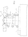
- FIGS. 4 and 5 show, as a further possible embodiment, a support plate 2a, of which only one half, ie the front half, is shown in FIGS. 4 and 5 and which is formed symmetrically to a central plane M which intersects the longitudinal axis of the support plate 2a perpendicularly is.
- the support plate in turn consists of the binding plate 15, which is formed from a corrosion-resistant metal, has a flat upper side and the cross section of which decreases somewhat from the center of the support plate 2 to the two ends.
- the support plate 16 corresponding to the support plate 4 is provided, which can be fastened together with the binding plate using screws 17 to the top of the ski 1, not shown.
- the binding plate 15 projects with two regions 15 'in the longitudinal direction of the ski over the support plate 16. At both ends, the binding plate 15 is each provided with an elongated hole 18, which extends in the longitudinal direction of this plate and is provided in the middle of the plate and which is countersunk on the upper side of the binding plate 15, ie is provided with an additional widened recess 19.
- the recess 19 serves, inter alia, to receive the head 20 of a screw 21 used as a guide element.
- the bearing plate 23 or the nut thread piece 22 provided there are spaced from the underside of the binding plate in the direction of the axis of the screw 21.
- the screw 21 is enclosed by a coiled compression spring 24, which is supported at one end on the underside of the binding plate in the region of the elongated hole 18 and on the top of the plate 23.
- the compression spring 24, which surrounds the threaded shaft of the screw 21 at a distance is held by a collar 22 ′ formed on the nut thread piece 22, which directly adjoins the plate 23 and has a larger cross section than the screw diameter 21.
- the width of the elongated hole 18 is adapted to the diameter of the screw 21, so that the screw 21 and the elongated hole 18 ensure that the binding plate 15 is guided as precisely as possible at the respective end in such a way that a relative movement between this end of the binding plate and the guide piece provided on the ski, namely screw 21, lateral deflection of the respective end of the binding plate 15 with respect to the ski is avoided.
- the screw 21 can be designed such that it is only provided with a thread at its end screwed into the nut thread piece 22, but otherwise has a smooth cylindrical outer surface.
- the compression spring 23 largely allows the ski to bend in such a way that its underside or tread assumes a covex course, the support plate 23 or the part of the ski there under elastic deformation the compression spring 24 approaches the respective end of the binding plate 15. Due to the elastic ring 25 arranged between the screw head 20 and the bottom of the recess 19, deformation of the ski 1 in the reverse direction is also possible in a small area.
- FIG. 5 shows, in particular, the screw head 20 and the elastic ring 25 are completely accommodated in the recess 19, so that the upper side of the binding plate 15 is flat over the entire length, that is to say in particular none over the upper side of the binding plate 15 above elements are provided.
- an optimal damping of vibrations in the ski is achieved by the elastic rings 25 and the compression springs 24, so that in turn a significantly improved skiing behavior can be achieved.
- the spring constant for the compression springs 24 can be chosen so that the desired bending line of the ski is not changed with optimal damping.
- the external guide elements formed by the screws 21 in turn achieve a very positive, torsion-free guide between the support plate 2a and the ski, with the advantage of improved ski guidance, smoother running and improved edge grip.
Landscapes
- Fittings On The Vehicle Exterior For Carrying Loads, And Devices For Holding Or Mounting Articles (AREA)
- Road Paving Structures (AREA)
Applications Claiming Priority (4)
| Application Number | Priority Date | Filing Date | Title |
|---|---|---|---|
| DE29603405U DE29603405U1 (de) | 1996-02-24 | 1996-02-24 | Tragplatte |
| DE29603405U | 1996-02-24 | ||
| DE19654410 | 1996-12-24 | ||
| DE19654410A DE19654410A1 (de) | 1996-02-24 | 1996-12-24 | Tragplatte |
Publications (2)
| Publication Number | Publication Date |
|---|---|
| EP0791378A2 true EP0791378A2 (fr) | 1997-08-27 |
| EP0791378A3 EP0791378A3 (fr) | 1998-06-24 |
Family
ID=26032809
Family Applications (1)
| Application Number | Title | Priority Date | Filing Date |
|---|---|---|---|
| EP97102776A Withdrawn EP0791378A3 (fr) | 1996-02-24 | 1997-02-20 | Plaque support |
Country Status (1)
| Country | Link |
|---|---|
| EP (1) | EP0791378A3 (fr) |
Cited By (4)
| Publication number | Priority date | Publication date | Assignee | Title |
|---|---|---|---|---|
| DE29715468U1 (de) * | 1997-08-28 | 1997-10-16 | Scott Sports Groupe Europe, Givisiez | Gleitbrett, vorzugsweise Ski |
| FR2777792A1 (fr) * | 1998-04-28 | 1999-10-29 | Patrice Marie Kopp | Dispositif pour faire plaquer les skis sur la neige afin de controler les flottements des skis et d'optimiser les performances. systeme de plaque avec bras amortisseurs fixe au ski et sur lequel est monte la fixation |
| FR2810251A1 (fr) * | 2000-06-19 | 2001-12-21 | Rossignol Sa | Ski alpin |
| EP2036596A1 (fr) * | 2007-09-14 | 2009-03-18 | Daniel Brillat | Dispositif amortisseur pour une fixation de chaussure sur une planche de glisse ou de roulage et procédé de mise en oeuvre de ce dispositif |
Family Cites Families (4)
| Publication number | Priority date | Publication date | Assignee | Title |
|---|---|---|---|---|
| DE2752206C3 (de) * | 1977-11-23 | 1986-03-27 | Bernhard 5500 Trier Kirsch | Sohlenplatte für Skibindungen |
| IT1242750B (it) * | 1990-07-30 | 1994-05-17 | Nordica Spa | Dispositivo per l'assorbimento delle vibrazioni, particolarmente per sci |
| AT401009B (de) * | 1992-07-15 | 1996-05-28 | Fischer Gmbh | Ski |
| DE4402662A1 (de) * | 1994-01-29 | 1995-08-03 | Franz Voelkl Gmbh & Co Ski Ten | Ski sowie Bindungsplatte für einen Ski |
-
1997
- 1997-02-20 EP EP97102776A patent/EP0791378A3/fr not_active Withdrawn
Cited By (6)
| Publication number | Priority date | Publication date | Assignee | Title |
|---|---|---|---|---|
| DE29715468U1 (de) * | 1997-08-28 | 1997-10-16 | Scott Sports Groupe Europe, Givisiez | Gleitbrett, vorzugsweise Ski |
| FR2777792A1 (fr) * | 1998-04-28 | 1999-10-29 | Patrice Marie Kopp | Dispositif pour faire plaquer les skis sur la neige afin de controler les flottements des skis et d'optimiser les performances. systeme de plaque avec bras amortisseurs fixe au ski et sur lequel est monte la fixation |
| FR2810251A1 (fr) * | 2000-06-19 | 2001-12-21 | Rossignol Sa | Ski alpin |
| EP1166834A1 (fr) * | 2000-06-19 | 2002-01-02 | Skis Rossignol S.A. | Ski alpin |
| US6619688B2 (en) | 2000-06-19 | 2003-09-16 | Skis Rossignol S.A. | Alpine ski |
| EP2036596A1 (fr) * | 2007-09-14 | 2009-03-18 | Daniel Brillat | Dispositif amortisseur pour une fixation de chaussure sur une planche de glisse ou de roulage et procédé de mise en oeuvre de ce dispositif |
Also Published As
| Publication number | Publication date |
|---|---|
| EP0791378A3 (fr) | 1998-06-24 |
Similar Documents
| Publication | Publication Date | Title |
|---|---|---|
| DE3029951C2 (fr) | ||
| EP0039765B1 (fr) | Dispositif pour le montage de plaques flexibles sur un cylindre de plaques pour rotatives | |
| EP1077861B1 (fr) | Systeme de securite en cas de collision pour colonne de direction | |
| DE4020212C3 (de) | Ski, insbesondere Alpinski | |
| DE19654410A1 (de) | Tragplatte | |
| DE3301413C2 (de) | Vorrichtung zur Befestigung eines Dachgepäckträgers , Skihalters od. dgl. auf einem Fahrzeugdach | |
| DE2121180B2 (de) | Mittenbefestigung für Blattfedern | |
| EP0122520A2 (fr) | Porte-bagages pour véhicules à deux roues | |
| DE19828382A1 (de) | Anordnung zum Befestigen eines einen Hohlquerschnitt aufweisenden Pfostens am Blendrahmen eines Fensters oder einer Türe aus Kunststoff oder Leichtmetall | |
| EP2151266B1 (fr) | Planche de glisse sur neige | |
| DE3820243C2 (de) | Spannklemme und Befestigungsanordnung für Eisenbahnschienen | |
| DE4402662A1 (de) | Ski sowie Bindungsplatte für einen Ski | |
| DE4108175C2 (de) | Befestigungsvorrichtung | |
| EP0012265A1 (fr) | Dispositif de fixation de rails | |
| DE202019104713U1 (de) | Fahrrad-Sattelstütze | |
| AT3309U1 (de) | Plattenförmiges tragelement, insbesondere für eine schibindung | |
| DE4209992C2 (de) | Ski | |
| AT403888B (de) | Ski, insbesondere alpinski | |
| DE19511080A1 (de) | Ski, Snowbord oder dergleichen Schnee-Gleitelement | |
| WO2002049727A1 (fr) | Ski, en particulier ski alpin | |
| EP1163937A2 (fr) | Plaque de surélévation | |
| DE3006428C2 (fr) | ||
| DE2528329A1 (de) | Schraubsicherung | |
| DE29721555U1 (de) | Spannvorrichtung | |
| DE3120162A1 (de) | Drueckerverbindung |
Legal Events
| Date | Code | Title | Description |
|---|---|---|---|
| PUAI | Public reference made under article 153(3) epc to a published international application that has entered the european phase |
Free format text: ORIGINAL CODE: 0009012 |
|
| AK | Designated contracting states |
Kind code of ref document: A2 Designated state(s): AT CH DE DK FR IT LI NL SE |
|
| AX | Request for extension of the european patent |
Free format text: SI PAYMENT 970314 |
|
| PUAL | Search report despatched |
Free format text: ORIGINAL CODE: 0009013 |
|
| AK | Designated contracting states |
Kind code of ref document: A3 Designated state(s): AT CH DE DK FR IT LI NL SE |
|
| AX | Request for extension of the european patent |
Free format text: SI PAYMENT 970314 |
|
| STAA | Information on the status of an ep patent application or granted ep patent |
Free format text: STATUS: THE APPLICATION IS DEEMED TO BE WITHDRAWN |
|
| 18D | Application deemed to be withdrawn |
Effective date: 19981229 |