EP0791417B1 - Lingotière de type caterpillar pour une installation de coulée continue - Google Patents
Lingotière de type caterpillar pour une installation de coulée continue Download PDFInfo
- Publication number
- EP0791417B1 EP0791417B1 EP97890015A EP97890015A EP0791417B1 EP 0791417 B1 EP0791417 B1 EP 0791417B1 EP 97890015 A EP97890015 A EP 97890015A EP 97890015 A EP97890015 A EP 97890015A EP 0791417 B1 EP0791417 B1 EP 0791417B1
- Authority
- EP
- European Patent Office
- Prior art keywords
- shells
- tracked
- links
- ingot mould
- mould according
- Prior art date
- Legal status (The legal status is an assumption and is not a legal conclusion. Google has not performed a legal analysis and makes no representation as to the accuracy of the status listed.)
- Expired - Lifetime
Links
Images

Classifications
-
- B—PERFORMING OPERATIONS; TRANSPORTING
- B22—CASTING; POWDER METALLURGY
- B22D—CASTING OF METALS; CASTING OF OTHER SUBSTANCES BY THE SAME PROCESSES OR DEVICES
- B22D11/00—Continuous casting of metals, i.e. casting in indefinite lengths
- B22D11/06—Continuous casting of metals, i.e. casting in indefinite lengths into moulds with travelling walls, e.g. with rolls, plates, belts, caterpillars
- B22D11/0637—Accessories therefor
- B22D11/0648—Casting surfaces
- B22D11/0657—Caterpillars
Definitions
- the invention relates to a crawler mold for a continuous casting plant with two mutually opposite, oppositely rotating caterpillars, which between their interacting chain strands delimit the mold cavity, the Chain links of the two caterpillars in the area of the interacting chain strands shells forming a round cross-section are formed.
- molds serve on the one hand to shape the cast Strand and, on the other hand, one necessary for rapid solidification of the strand intensive heat dissipation.
- Co-rotating molds have stationary ones
- Chill molds have the advantage that for a given, both the shape and the Heat dissipation promoting intensive contact between the strand surface and Mold shape due to the lack of a relative sliding movement between the strand and Chill mold achieves higher casting speeds and thus higher casting performances can be.
- the close contact between the mold and So far the strand can only be reached with flat strand cross-sections whose material shrinkage is divided into several parts by slight relative movements of the lateral web walls Let mold shapes compensate (AT-B 381.878).
- the invention is therefore based on the object to eliminate these shortcomings and a To create caterpillar mold of the type described, which is a rational and nevertheless enables high quality continuous casting of round cross sections, whereby under circular cross-section in addition to the circular cross-section also oval and through arch and short straight sections are to be understood as composite cross sections.
- the invention solves this problem in that the mutually assigned shells have intermeshing longitudinal edges which are relatively movable transversely to the direction of rotation and the chain links in the area of the interacting chain dreams in the sense of a Reduction of the round cross-section is performed or can be subjected to pressure. Due to the interlocking longitudinal edges of the two resulting the round cross-section Shells can be relative despite a closed cross-sectional shape shifted to each other and thus cross-sectional reductions can be achieved.
- a corresponding merging and pressure loading can be the one another assigned shells during their movement along the mold cavity press on the cast strand and therefore also follow signs of shrinkage and shrinkage without risk of peeling between the shell shape and the strand surface in the entire mold area, so that regardless of the casting or circulation speed There is always intensive contact between the mold and the strand at all points guarantees and on the one hand the exact shape, on the other hand the high heat flow density for cooling is given.
- the strong cooling effect due to the on the strand Pressable shells allow the use of the caterpillar mold as a primary mold and ensures rapid solidification of the strand here.
- the caterpillar mold can also used as a secondary mold for further cooling an already solidified strand become, with which a solidification accelerates and the emergence of segregations in the Core area is avoided because of the rapid solidification process.
- the longitudinal edges can the shells are bevelled in opposite directions and can be at least one of the other assigned shells in the direction of curvature be designed to be flexible, so that the reduction in cross section by elastic deformation of at least one of the Shells comes about.
- a suitable material for this is the shell material flexible material such as copper alloys or the like, which is also good Provides heat dissipation.
- some have Chain links have a substantially U-shaped base body and the other chain links an essentially stamp-shaped, fitting between the leg walls of the U-shaped base body engaging base body, the inner apex area of the U-shaped base body and the concave end face area of the stamp-shaped Base body that form shells that complement the round cross-section. Due to this base body, which can be pushed directly into one another, there is an elastic deformation of the shells unnecessarily and it can make relatively large relative movements without Risk of cracking and without plastic deformation of the shells.
- At least one of the Track chains in a suitably supported and resilient frame or the like. be stored so that correspondingly high pressure forces can be applied.
- the caterpillar mold according to the invention is of course suitable for the vertical Continuous casting as a vertical mold with the need to convert the resulting strand Having to divert further processing into the horizontal. Because of the good ones Heat dissipation conditions and that resulting from the moving mold However, the caterpillar mold is also preferably suitable for use as a peeling effect moving oblique or horizontal mold, with the mold cavity in the inlet area delimiting chain dreams between the assigned shells the chain links is provided sealing piston protruding from the melt, by an inner pouring tube connected to a pouring device into the mold cavity flows out.
- Such a horizontal mold arrangement avoids a stronger one Deflection of the strand after the mold, reduces the required height and also has the advantage that the ferrostatic pressure during continuous casting remains approximately the same over the entire course of the strand.
- the one with the mold achievable pressure between shells and strand and a corresponding mold length can achieve casting speeds between 20 and 40 m / min, and more be, the supply of the melt in a suitable manner via a pouring tube takes place through the closing piston closing the mold cavity in the Mold cavity leads.
- the chain links enclose the shells in the Cross section adapted to the round cross section of the strand and slide relatively to the piston at the pouring speed in the pouring direction over the fixed piston away, immediately after the piston due to the high heat dissipation the chain links the solidification of the strand begins and continues continuously and forms a strand shell.
- the locking piston consists of a ceramic body with a circumferential side Sliding layer, preferably made of sintered metal, and the pouring tube has a funnel mouth on, preferably the sliding layer at a distance in front of the mouth End face ends, can also be in the delicate initial area of strand formation perfect technological conditions can be achieved.
- the ceramic piston is heat-insulating and prevents overheating of the outer sliding layer, which, if necessary provided with lubrication, a low-friction sliding on the Chain links allows.
- the funnel-shaped pouring tube brings a uniform Spread of the melt over the mold cross-section and the uniform Formation of the strand shell along the round cross-section with itself.
- the distance between the mouth-side end face of the locking piston and the circumferential side Sliding layer interrupts any heat conduction to the sliding layer, so that also a clean start of solidification for the strand shell results.
- the interacting chain strands are expediently located one above the other and overlap the shells of the lower chain links with theirs Longitudinal edges of the shells of the upper chain links outside, so that there are no sealing difficulties there and the melt can be easily absorbed.
- An advantageous one constructive solution arises if the upper chain center against the firmly supported lower chain center is pressure-resistant, which means that only one of the caterpillar tracks must be stored adjustable and, moreover, the gravity of these movable mounted crawler chains for the pressure load of the interacting chain strands is usable.
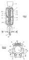
- FIGS. 1 and 2 comprises a vertical continuous casting system 1 a casting device 2, a caterpillar mold 3 and one on the caterpillar mold 3 subsequent deformation device 4 with subsequent deflection rollers 41 for the emerging strand ST.
- the caterpillar mold 3 has two opposing, oppositely rotating caterpillar tracks 5, 6, which interact between their Chain strands 51, 61 limit the mold cavity 7.
- the chain links 8, 9 of the two caterpillar tracks 5, 6 form shells 81, 91 which interact in the area of the Add chain strands 51, 61 to a round cross section 10.
- each other Shells 81, 91 interlocking longitudinal edges 82, 92 which are bevelled in opposite directions are and thus support each other relatively movable.
- support rollers 11, 12 are the chain links 8, 9 in the area of the interacting chain runs 51, 61 in the sense of a reduction of the round cross section 10, the a chain links 8 form a flexible shell 81.
- These are chain links 8 made of a copper alloy or the like and have in the region of curvature on the back of the shell facing away from the longitudinal slots 83 to by flexible Deformation relative to the chain links 9 to achieve and adapt to a cross-sectional reduction.
- the chain dreams 51, 61 thus run to compensate for the cross-sectional shrinkage of the solidifying Stranges ST conical together in the direction of rotation, which from the outset by a corresponding Inclination of the caterpillar tracks can be taken into account.
- 3 is a horizontal Continuous caster 101 with a casting device 102 and a horizontal crawler mold 103 provided.
- the crawler mold has two opposing, oppositely rotating tracks 105, 106 between their interacting chain runs 151, 161 delimit the mold cavity 107, the chain links 108, 109 complementing each other to form a round cross section 110
- the chain links 108 of the caterpillar tracks 105 are, however, with an im essential U-shaped base body 183 and the chain links 109 of the crawler belt 106 equipped with a substantially stamp-shaped base body 193, which stamp-shaped base body 193 fits between those forming the longitudinal edges 182 Leg walls of the base body 183 engages.
- support wheels 111, 112 for a mutual pressure load, the support wheels for the track chain below 105 via a pressing device 113 and the support wheels for the one above Track chain 106 can be pressure-loaded via a pressing device 114.
- the mold cavity 107 is in the inlet area 15 with one between the chain links 108, 109 projecting closure piston 16 closed, through which one to the Pouring device 102 opens out pouring tube 17 with a funnel mouth 18.
- the locking piston 16 has a ceramic body 116 and is circumferential equipped with a sliding layer 117, between sliding layer 117 and a thermally insulating insulating region 119 remains on the mouth-side end face 118. That through the casting device 102 and the pouring tube 17 into the mold cavity 107 inflowing melting material SM is due to the close contact with the chain links deducted and promoted and at the same time to form a continuous Strand shell S cooled intensely, so that a perfect strand ST with a round cross-section arises.
- the base bodies 183, 193 of the chain links 108, 109 with their concave apex areas on the one hand and their concaves End faces on the other hand, the shells 181, 191 form different round cross sections limit, for example, an approximately circular cross section 110 according to FIG. 5 or a rounded square or rectangular cross section 210 according to FIG. 6. It is only important that there are no angular cross-sections, as these Edges especially the even pressure propagation and distribution in the strand shell hinder the strand circumference and thus the cooling and solidification conditions affect.
Landscapes
- Engineering & Computer Science (AREA)
- Mechanical Engineering (AREA)
- Continuous Casting (AREA)
- Molds, Cores, And Manufacturing Methods Thereof (AREA)
Claims (9)
- Lingotière de type chenille (3) pour une installation de coulée continue (1) comportant deux chaínes de chenille (5, 6) circulant en sens inverse, placées l'une en face de l'autre, délimitant, entre leurs brins de chaínes (51, 61) coopérants, l'espace creux de coquille (7), les maillons de chaínes (8, 9) des deux chaínes de chenilles (5, 6) constituant, dans la zone des brins de chaínes en coopération, des coques (81, 91) se complétant pour former une section transversale ronde (10), caractérisée en ce que les coques (81, 91; 181, 191) tournées les unes vers les autres présentent des bords longitudinaux (82, 92; 182, 192) s'engageant les uns dans les autres avec en mobilité relative en direction de la circulation, et les maillons de chaínes (8, 9; 108, 109) étant guidés ou susceptibles d'être chargés par une pression dans la zone des brins de chaínes (51, 61; 151, 161) coopérants, dans le sens d'une réduction de la section transversale ronde (10, 110, 210).
- Lingotière de type chenille selon la revendication 1, caractérisée en ce que les bords longitudinaux (82, 92) des coques (81, 91) sont biseautés de façon mutuellement identique et au moins une des coques (81) associées les unes aux autres étant réalisée avec une élasticité de flexion dans la direction de la courbure.
- Lingotière de type chenille selon la revendication 2, caractérisée en ce que les maillons de chaíne (8) constituant la coque (81) présentant une élasticité en flexion comportent des fentes longitudinales (83), dans la zone de courbure, sur la face arrière opposée à la coque.
- Lingotière de type chenille selon la revendication 1, caractérisée en ce que des premiers maillons de chaíne (108) présentent un corps de base (183) sensiblement en forme de U, et les autres maillons de chaínes (109) présentent un corps de base (193) sensiblement en forme de poinçon, s'engageant de façon ajustée entre les parois de branche du corps de base (183) en forme de U, la zone du sommet intérieur du corps de base (183) en forme de U et la zone de face frontale concave du corps de base (193) en forme de poinçon constituant les coques (181, 191) se complétant pour donner la section transversale ronde (110, 210).
- Lingotière de type chenille selon l'une des revendications 1 à 4, caractérisée par leur utilisation comme coquille oblique ou horizontale (103), à mouvement conjoint, où, dans la zone d'entrée (15) des brins de chaínes (151, 161) délimitant l'espace creux de coquille (107), est prévu un piston de fermeture (16) faisant saillie, de façon étanche par rapport à la masse fondue, entre les coques (181, 191) associées les unes aux les autres des maillons de chaínes (108, 109), piston de fermeture au moyen duquel un tube de coulée (17), raccordé à un dispositif de coulée (102), débouche dans l'espace creux de coquille (107).
- Lingotière de type chenille selon la revendication 5, caractérisée en ce que le piston de fermeture (16) est constitué d'un corps en céramique (116) ayant une couche de glissement (117) du côté périphérique, de préférence réalisée en métal fritté, et le tube de coulée (17) présente une embouchure en entonnoir (18).
- Lingotière de type chenille selon la revendication 6, caractérisée en ce que la couche de glissement (117) s'achève à distance avant la face frontale (118) située côté embouchure.
- Lingotière de type chenille selon la revendication 5, caractérisée en ce que les brins de chaínes (151, 161) coopérants sont situés les uns au-dessus des autres et les coques (181) des maillons de chaínes inférieurs (108) entourent extérieurement, par leurs bords longitudinaux (182), les coques (191) des maillons de chaínes supérieurs (109).
- Lingotière de type chenille selon la revendication 8, caractérisée en ce que le brin de chaíne supérieur est susceptible d'être chargé par une pression contre le brin de chaíne inférieur soutenu fermement.
Applications Claiming Priority (3)
| Application Number | Priority Date | Filing Date | Title |
|---|---|---|---|
| AT30896 | 1996-02-20 | ||
| AT308/96 | 1996-02-20 | ||
| AT0030896A AT405254B (de) | 1996-02-20 | 1996-02-20 | Raupenkokille für eine stranggussanlage |
Publications (2)
| Publication Number | Publication Date |
|---|---|
| EP0791417A1 EP0791417A1 (fr) | 1997-08-27 |
| EP0791417B1 true EP0791417B1 (fr) | 2000-04-12 |
Family
ID=3487116
Family Applications (1)
| Application Number | Title | Priority Date | Filing Date |
|---|---|---|---|
| EP97890015A Expired - Lifetime EP0791417B1 (fr) | 1996-02-20 | 1997-01-23 | Lingotière de type caterpillar pour une installation de coulée continue |
Country Status (5)
| Country | Link |
|---|---|
| US (1) | US5899260A (fr) |
| EP (1) | EP0791417B1 (fr) |
| AT (1) | AT405254B (fr) |
| CZ (1) | CZ288903B6 (fr) |
| DE (1) | DE59701426D1 (fr) |
Families Citing this family (5)
| Publication number | Priority date | Publication date | Assignee | Title |
|---|---|---|---|---|
| IT1295884B1 (it) * | 1997-10-28 | 1999-05-28 | Techint Spa | Lingottiera perfezionata strisciante a catena per un impianto di colata continua |
| CN100381275C (zh) * | 2006-05-12 | 2008-04-16 | 宋旭 | 全自动履带式生物质压块机 |
| ITVR20130269A1 (it) * | 2013-12-04 | 2015-06-05 | B2Ft S R L | Impianto per la produzione, mediante colata, di lingotti in metallo |
| WO2016166576A1 (fr) * | 2015-04-17 | 2016-10-20 | B2Ft S.R.L. | Appareil pour la production de lingots de métal par coulée |
| DE102017221095A1 (de) * | 2016-11-29 | 2018-05-30 | Sms Group Gmbh | Raupengießmaschine und Verfahren zum Herstellen eines Gießguts aus flüssigem Metall |
Family Cites Families (15)
| Publication number | Priority date | Publication date | Assignee | Title |
|---|---|---|---|---|
| US342920A (en) * | 1886-06-01 | And hoeace w | ||
| US1139887A (en) * | 1914-11-28 | 1915-05-18 | Continuous Casting Corp | Continuous casting-machine. |
| US1841297A (en) * | 1928-04-26 | 1932-01-12 | John E Perry | Apparatus and method of continuous casting of steel |
| DE688836C (de) * | 1937-10-26 | 1940-03-04 | Dortmund Hoerder Huettenver Ak | Vorrichtung zum fortlaufenden Giessen von Straenge |
| CH508433A (de) * | 1970-06-24 | 1971-06-15 | Prolizenz Ag C O Schweiz Kredi | Düse für die Zuführung des geschmolzenen Metalles beim Bandgiessen in Raupenkokille |
| US4331195A (en) * | 1978-08-08 | 1982-05-25 | Webber C Eugene | Continuous casting machine |
| JPS5756140A (en) * | 1980-04-23 | 1982-04-03 | Furukawa Electric Co Ltd:The | Method for continuously casting metal |
| DE3029223C2 (de) * | 1980-08-01 | 1984-09-27 | Fried. Krupp Gmbh, 4300 Essen | Einlauf für die Metallschmelze in Stranggießvorrichtungen |
| JPS5835048A (ja) * | 1981-08-26 | 1983-03-01 | Mitsubishi Heavy Ind Ltd | 水平連続鋳造装置用プラグ |
| AT381878B (de) | 1984-09-10 | 1986-12-10 | Voest Alpine Ag | Stranggiesskokille |
| JPS61176450A (ja) * | 1985-01-31 | 1986-08-08 | Ishikawajima Harima Heavy Ind Co Ltd | 無限軌道型連続鋳造設備 |
| ES2015527B3 (es) * | 1986-12-19 | 1990-09-01 | Mannesmann Ag | Dispositivo de colada para metales con un elemento rotativo de soporte continuo. |
| AT388688B (de) * | 1987-02-05 | 1989-08-10 | Stangl Kurt Dipl Ing | Vorrichtung zum giessen eines stahlstranges |
| US4738300A (en) * | 1987-04-16 | 1988-04-19 | Ishikawajima-Harima Jukogyo Kabushiki Kaisha | Endless track type continuous casting installation |
| JPH01130849A (ja) * | 1987-11-17 | 1989-05-23 | Ishikawajima Harima Heavy Ind Co Ltd | 無限軌道式連続鋳造機 |
-
1996
- 1996-02-20 AT AT0030896A patent/AT405254B/de not_active IP Right Cessation
-
1997
- 1997-01-23 EP EP97890015A patent/EP0791417B1/fr not_active Expired - Lifetime
- 1997-01-23 DE DE59701426T patent/DE59701426D1/de not_active Expired - Lifetime
- 1997-02-13 US US08/800,271 patent/US5899260A/en not_active Expired - Fee Related
- 1997-02-20 CZ CZ1997516A patent/CZ288903B6/cs not_active IP Right Cessation
Also Published As
| Publication number | Publication date |
|---|---|
| DE59701426D1 (de) | 2000-05-18 |
| CZ288903B6 (cs) | 2001-09-12 |
| AT405254B (de) | 1999-06-25 |
| CZ51697A3 (en) | 1997-09-17 |
| US5899260A (en) | 1999-05-04 |
| ATA30896A (de) | 1998-11-15 |
| EP0791417A1 (fr) | 1997-08-27 |
Similar Documents
| Publication | Publication Date | Title |
|---|---|---|
| DE3322424C2 (fr) | ||
| DE4306943C2 (de) | Anfahrkopf für eine Vertikal-Stranggießanlage | |
| DE19637402A1 (de) | Bandgießen | |
| EP0791417B1 (fr) | Lingotière de type caterpillar pour une installation de coulée continue | |
| EP0107068A1 (fr) | Procédé pour la coulée continue horizontale de métaux, en particulier de l'acier | |
| DE1957332A1 (de) | Stranggiesskokille zum Giessen von Metall,insbesondere Stahl | |
| DE3044575C2 (de) | Verfahren und Stranggießkokille zum kontinuierlichen horizontalen Stranggießen | |
| DE68903964T2 (de) | Stranggiessmaschine vom typ raupenkette. | |
| DE3200641A1 (de) | Verfahren und vorrichtung zum giessen von, eine abriebbestaendige einlage aufweisenden leichtmetall-kolben | |
| DE1188769B (de) | Einrichtung zum kontinuierlichen Giessen von Metallstangen unbegrenzter Laenge | |
| DE1809744C3 (de) | Verfahren zum Stranggießen von Metallen, sowie Stranggießkokille zur Durchführung des Verfahrens | |
| DE69807815T2 (de) | Kettenartige Stranggusskokille | |
| DE69703582T2 (de) | Vertikal stranggusskokille mit aufsatz | |
| DE19725435C2 (de) | Verfahren und Vorrichtung zum kontinuierlichen Gießen von Metall | |
| CH671533A5 (fr) | ||
| DD143221A5 (de) | Kontinuierlich gegossener stahlstrang und verfahren zur herstellung | |
| CH363129A (de) | Verfahren zum kontinuierlichen Giessen von Metallsträngen und Kokille zum Durchführen des Verfahrens | |
| DE3802202C2 (fr) | ||
| DE2613363B2 (de) | Kühlvorrichtung unterhalb einer Stranggießkokille | |
| DE2264454A1 (de) | Strangstuetzelemente | |
| DE3102055C2 (de) | Waagerechte Kaltkammer-Druckgießmaschine | |
| EP0160835B1 (fr) | Procédé et dispositif pour la coulée continue de métal dans une lingotière à parois refroidies animées d'un mouvement circulaire | |
| DE2457422C3 (de) | Vorrichtung zum Stranggießen aus Schichten metallischer Schmelze | |
| DE3028247A1 (de) | Vorrichtung zur erzeugung von eisen-ausgangsmaterialien | |
| DE1508799B1 (de) | Vorrichtung zur zufuhr einer stahlschmelze zu stranggiess kokillen |
Legal Events
| Date | Code | Title | Description |
|---|---|---|---|
| PUAI | Public reference made under article 153(3) epc to a published international application that has entered the european phase |
Free format text: ORIGINAL CODE: 0009012 |
|
| AK | Designated contracting states |
Kind code of ref document: A1 Designated state(s): CH DE FR GB IT LI LU |
|
| 17P | Request for examination filed |
Effective date: 19971001 |
|
| GRAG | Despatch of communication of intention to grant |
Free format text: ORIGINAL CODE: EPIDOS AGRA |
|
| GRAG | Despatch of communication of intention to grant |
Free format text: ORIGINAL CODE: EPIDOS AGRA |
|
| GRAH | Despatch of communication of intention to grant a patent |
Free format text: ORIGINAL CODE: EPIDOS IGRA |
|
| 17Q | First examination report despatched |
Effective date: 19990922 |
|
| GRAH | Despatch of communication of intention to grant a patent |
Free format text: ORIGINAL CODE: EPIDOS IGRA |
|
| GRAA | (expected) grant |
Free format text: ORIGINAL CODE: 0009210 |
|
| AK | Designated contracting states |
Kind code of ref document: B1 Designated state(s): CH DE FR GB IT LI LU |
|
| REG | Reference to a national code |
Ref country code: CH Ref legal event code: EP |
|
| REG | Reference to a national code |
Ref country code: CH Ref legal event code: NV Representative=s name: DIPL.-ING. W. STEUDTNER |
|
| REF | Corresponds to: |
Ref document number: 59701426 Country of ref document: DE Date of ref document: 20000518 |
|
| ET | Fr: translation filed | ||
| ITF | It: translation for a ep patent filed | ||
| GBT | Gb: translation of ep patent filed (gb section 77(6)(a)/1977) |
Effective date: 20000626 |
|
| PLBE | No opposition filed within time limit |
Free format text: ORIGINAL CODE: 0009261 |
|
| STAA | Information on the status of an ep patent application or granted ep patent |
Free format text: STATUS: NO OPPOSITION FILED WITHIN TIME LIMIT |
|
| 26N | No opposition filed | ||
| REG | Reference to a national code |
Ref country code: GB Ref legal event code: IF02 |
|
| PGFP | Annual fee paid to national office [announced via postgrant information from national office to epo] |
Ref country code: FR Payment date: 20050128 Year of fee payment: 9 |
|
| PG25 | Lapsed in a contracting state [announced via postgrant information from national office to epo] |
Ref country code: FR Free format text: LAPSE BECAUSE OF NON-PAYMENT OF DUE FEES Effective date: 20060131 |
|
| REG | Reference to a national code |
Ref country code: FR Ref legal event code: ST Effective date: 20060929 |
|
| PGFP | Annual fee paid to national office [announced via postgrant information from national office to epo] |
Ref country code: LU Payment date: 20070124 Year of fee payment: 11 |
|
| GBPC | Gb: european patent ceased through non-payment of renewal fee |
Effective date: 20070123 |
|
| PG25 | Lapsed in a contracting state [announced via postgrant information from national office to epo] |
Ref country code: GB Free format text: LAPSE BECAUSE OF NON-PAYMENT OF DUE FEES Effective date: 20070123 |
|
| REG | Reference to a national code |
Ref country code: CH Ref legal event code: PCAR Free format text: PATENTANWALTSBUREAU STEUDTNER;AHORNWEG 12;5702 NIEDERLENZ (CH) |
|
| PGFP | Annual fee paid to national office [announced via postgrant information from national office to epo] |
Ref country code: GB Payment date: 20060125 Year of fee payment: 10 |
|
| PG25 | Lapsed in a contracting state [announced via postgrant information from national office to epo] |
Ref country code: LU Free format text: LAPSE BECAUSE OF NON-PAYMENT OF DUE FEES Effective date: 20080123 |
|
| REG | Reference to a national code |
Ref country code: CH Ref legal event code: PCAR Free format text: PATENTANWALTSBUERO STEUDTNER;AHORNWEG 6;5702 NIEDERLENZ (CH) |
|
| REG | Reference to a national code |
Ref country code: CH Ref legal event code: PUE Owner name: SIEMENS VAI METALS TECHNOLOGIES GMBH Free format text: HULEK, ANTON, DIPL.-ING.#GOGLERFELDGASSE 15#A-4040 LINZ (AT) -TRANSFER TO- SIEMENS VAI METALS TECHNOLOGIES GMBH#TURMSTRASSE 44#4031 LINZ (AT) Ref country code: CH Ref legal event code: NV Representative=s name: SIEMENS SCHWEIZ AG |
|
| REG | Reference to a national code |
Ref legal event code: R082 Ref document number: 59701426 Ref country code: DE Ref legal event code: R082 Ref document number: 59701426 Country of ref document: DE Representative=s name: DANIEL OLIVER MAIER, DE |
|
| REG | Reference to a national code |
Ref country code: DE Ref legal event code: R082 Ref document number: 59701426 Country of ref document: DE |
|
| REG | Reference to a national code |
Ref country code: DE Ref legal event code: R081 Ref document number: 59701426 Country of ref document: DE Owner name: SIEMENS VAI METALS TECHNOLOGIES GMBH, AT Free format text: FORMER OWNER: HULEK, ANTON, DIPL.-ING., LINZ, AT Effective date: 20120515 |
|
| PGFP | Annual fee paid to national office [announced via postgrant information from national office to epo] |
Ref country code: DE Payment date: 20150320 Year of fee payment: 19 Ref country code: IT Payment date: 20150128 Year of fee payment: 19 |
|
| PGFP | Annual fee paid to national office [announced via postgrant information from national office to epo] |
Ref country code: CH Payment date: 20150402 Year of fee payment: 19 |
|
| REG | Reference to a national code |
Ref country code: CH Ref legal event code: PFA Owner name: PRIMETALS TECHNOLOGIES AUSTRIA GMBH, AT Free format text: FORMER OWNER: SIEMENS VAI METALS TECHNOLOGIES GMBH, AT |
|
| REG | Reference to a national code |
Ref country code: DE Ref legal event code: R119 Ref document number: 59701426 Country of ref document: DE |
|
| REG | Reference to a national code |
Ref country code: CH Ref legal event code: PL |
|
| PG25 | Lapsed in a contracting state [announced via postgrant information from national office to epo] |
Ref country code: CH Free format text: LAPSE BECAUSE OF NON-PAYMENT OF DUE FEES Effective date: 20160131 Ref country code: LI Free format text: LAPSE BECAUSE OF NON-PAYMENT OF DUE FEES Effective date: 20160131 Ref country code: DE Free format text: LAPSE BECAUSE OF NON-PAYMENT OF DUE FEES Effective date: 20160802 |
|
| PG25 | Lapsed in a contracting state [announced via postgrant information from national office to epo] |
Ref country code: IT Free format text: LAPSE BECAUSE OF NON-PAYMENT OF DUE FEES Effective date: 20160123 |