EP0791418A2 - Druckgussmaschine mit kombiniertem Positionier- und Pressdruckzylinder - Google Patents
Druckgussmaschine mit kombiniertem Positionier- und Pressdruckzylinder Download PDFInfo
- Publication number
- EP0791418A2 EP0791418A2 EP97300679A EP97300679A EP0791418A2 EP 0791418 A2 EP0791418 A2 EP 0791418A2 EP 97300679 A EP97300679 A EP 97300679A EP 97300679 A EP97300679 A EP 97300679A EP 0791418 A2 EP0791418 A2 EP 0791418A2
- Authority
- EP
- European Patent Office
- Prior art keywords
- docking
- shot
- chamber
- piston
- assembly
- Prior art date
- Legal status (The legal status is an assumption and is not a legal conclusion. Google has not performed a legal analysis and makes no representation as to the accuracy of the status listed.)
- Ceased
Links
- 238000003032 molecular docking Methods 0.000 title claims abstract description 116
- 150000001875 compounds Chemical class 0.000 title claims abstract description 8
- 238000004512 die casting Methods 0.000 title claims description 24
- 239000012530 fluid Substances 0.000 claims description 44
- 238000002347 injection Methods 0.000 claims description 22
- 239000007924 injection Substances 0.000 claims description 22
- 239000002184 metal Substances 0.000 claims description 14
- 239000000463 material Substances 0.000 claims description 11
- 230000007246 mechanism Effects 0.000 claims description 7
- 238000000034 method Methods 0.000 claims 2
- 230000003750 conditioning effect Effects 0.000 description 4
- 230000000712 assembly Effects 0.000 description 3
- 238000000429 assembly Methods 0.000 description 3
- 230000001143 conditioned effect Effects 0.000 description 2
- 238000012986 modification Methods 0.000 description 2
- 230000004048 modification Effects 0.000 description 2
- 229910000906 Bronze Inorganic materials 0.000 description 1
- 230000000903 blocking effect Effects 0.000 description 1
- 239000010974 bronze Substances 0.000 description 1
- 238000005266 casting Methods 0.000 description 1
- KUNSUQLRTQLHQQ-UHFFFAOYSA-N copper tin Chemical compound [Cu].[Sn] KUNSUQLRTQLHQQ-UHFFFAOYSA-N 0.000 description 1
- 230000008878 coupling Effects 0.000 description 1
- 238000010168 coupling process Methods 0.000 description 1
- 238000005859 coupling reaction Methods 0.000 description 1
- 230000001419 dependent effect Effects 0.000 description 1
- 229910001338 liquidmetal Inorganic materials 0.000 description 1
- 230000013011 mating Effects 0.000 description 1
Images


Classifications
-
- B—PERFORMING OPERATIONS; TRANSPORTING
- B22—CASTING; POWDER METALLURGY
- B22D—CASTING OF METALS; CASTING OF OTHER SUBSTANCES BY THE SAME PROCESSES OR DEVICES
- B22D17/00—Pressure die casting or injection die casting, i.e. casting in which the metal is forced into a mould under high pressure
- B22D17/08—Cold chamber machines, i.e. with unheated press chamber into which molten metal is ladled
- B22D17/12—Cold chamber machines, i.e. with unheated press chamber into which molten metal is ladled with vertical press motion
Definitions
- This invention relates to aspects of a die cast apparatus and more particularly, to a novel and unique docking/shot assembly for a vertical injection type die cast apparatus in which the docking and shot cylinders are constructed in one compound cylinder.
- this invention relates to the means for supporting the shot cylinder assembly in relation to the stationary front platen and the die body of a horizontal mold clamping type of die cast apparatus or machine.
- the apparatus for docking the injection sleeve into the gate of the mold or die and the apparatus for injecting the injectable metal into the mold or die have been accomplished by separate cylinders, making the apparatus complicated and to particularly occupy a substantial amount of space so as to interfere with other desired mechanisms located near the bottom of the die or mold.
- One such desired mechanism is a mechanism for actuating a movable core assembly, such mechanism located in the area near the bottom part of the die where previously constructed unwieldy structures for the separate docking cylinder and shot cylinder are located.
- the compound cylinder includes a first cylinder and generally an outer cylinder having a chamber in which is located a docking piston.
- the docking piston in turn has a cylinder chamber in which is located a shot piston.
- Ports and passageways for pressurized fluid are provided in both of the outer cylinder and the cylinder formed in the docking piston.
- valving is provided for causing pressurized fluid to first actuate the docking piston in the first chamber to dock the sleeve into the gate, and thereafter the shot piston is actuated in the cylinder of the docking piston to produce a shot of metal into the cavity of the die.
- the shot piston which is slidably mounted in the cylinder of the docking piston provides a surface which assists in the pressurized fluid forcing the docking piston upwardly to cause the injection sleeve to dock into the gate of the die. This is accomplished by the valving which initially prevents the shot piston from moving relative to the docking piston by reason of equal force on the top and bottom surfaces of the shot piston.
- the above-described docking/shot assembly can be applied to vertical/vertical die casting apparatus or to horizontal die casting apparatus.
- One aspect of this invention provides in the horizontal/vertical (HV) die casting apparatus a unique means for supporting the compound cylinder described above so that it can be tilted for receiving a charge of the injectable metal and then pivoted to the upright docking position.
- the front stationary platen includes a downwardly extending portion located between elongated support members for the platens.
- This downwardly extending portion has a cutout extending upwardly from its lower edge through the space between the elongated support members.
- a support bracket assembly is attached to the downwardly extending portions of the front stationary platen on each side of the cutout to support the docking/shot assembly.
- the support bracket depending from said downwardly extending portion has a support assembly for pivotally mounting the docking/shot assembly.
- This structure provides for the docking/shot assembly to be pivotally mounted on the support bracket assembly so as to be pivoted from a docking position through the space provided by the cutout to a tilted loading position and vice versa.
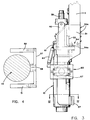
- reference numeral 1 designates a horizontal/vertical (HV) machine in which the horizontal mold clamping components are conventional.
- HV horizontal/vertical
- these conventional components include a stationary front platen 2 having tie rods 3 on which is supported a movable platen 4 which is horizontally movable with respect to the stationary platen 2.
- a die or mold 5 formed of two parts 5a and 5b is located between the platens 2 and 4.
- the die part 5a is mounted on the movable platen 4 and the die part 5b is mounted on the stationary front platen 2.
- the die parts 5a and 5b oppose each other and include cavities 6a and 6b forming a cavity in the split or mating plane X.
- An actuating rod is attached to the movable platen 4 and is attached to a toggle mechanism (not shown) which is actuated by a clamping cylinder (not shown), both of which are conventional.
- a clamping cylinder (not shown) which is actuated by a clamping cylinder (not shown), both of which are conventional.
- the clamping cylinder When the clamping cylinder is operated, the movable platen 4 is moved forward to clamp the die parts 5a and 5b closed so as to form cavity 6 in which injectable metal is injected through the gate 45 by means of the vertical injection type docking/shot assembly 10 which forms one major aspect of the present invention.
- the docking/shot assembly 10 is mounted on the front stationary platen 2 by means of the bracket support assembly 50.
- the entire die cast machine is mounted on the spaced beams 9a and 9b (Fig. 2).
- this type of apparatus is mounted with the docking/shot assembly 10 extending into a pit "P"; however, within the broadest aspect of this invention, the beams 9
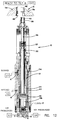
- Fig. 5 discloses the various components of the docking/shot assembly 10 which includes an outer docking cylinder 11 having a chamber in which is slidably mounted the docking piston 12.
- the chamber within docking cylinder 11 is divided by docking piston 12 into an upper chamber 13a and a lower chamber 13b.
- the upper chamber 13a is closed at the upper end of cylinder 11 by the cylinder top closure 14 and at the lower end of cylinder 11, the lower chamber 13b is closed by the cylinder bottom closure 15.
- Cylinder 11 has several openings or ports including the port or opening A communicating with the upper chamber 13a and the port or opening B which communicates with the passageway 16 formed by a recess in the inner wall of cylinder 11.
- Passageway 16 provides communication between port or opening B and port or opening 16a which extends through the walls of cylinder portion 20. As a result, passageway 16 provides for flow of fluid from upper chamber 24 to opening or port B and vice versa.
- the closure member or cap 15 at the lower end of the cylinder 11 includes the openings C, D, and E.
- the opening or port C communicates with opening E. These two openings or ports are provided for the inlet of pressurized fluid into the lower chamber 13b.
- a check valve 17 is provided for opening and closing the port E as will be explained hereinafter.
- the port or opening D is provided for the purpose of introducing an intensified pressurized fluid into the lower chamber 13b.
- the docking piston 12 includes an intermediate body portion 18 having a neck 19 integral therewith and extending upwardly through upper chamber 13a and through bore 21 of closure 14 and a cylinder portion 20 extending downwardly from the intermediate body portion 18.
- a bore 21a extends through the intermediate body 18 and neck 19 for receiving the piston rod 22 extending from the shot piston 23 located in the cylinder portion 20 of the docking piston 12.
- the chamber of the cylinder portion 20 includes the top chamber 24 and the lower chamber 25.
- Docking piston 12 is slidably mounted in cylinder 11 by bronze sleeve guide bearings 26, and 27.
- Guide bearing 27 is mounted within the inner wall of cylinder 11 by the bearing support 29.
- Item 30 is used to support seal 28.
- Neck 19 of docking piston 12 extends upwardly through a bore 33 in the cylinder top closure 14. It is guided by the sleeve guide bearing 26 between neck 19 and bore 33. Piston rod 22 is guided by sleeve guide bearing 34 located between piston rod 22 and bore 21 of the neck 19.
- Neck 19 is attached to an adaptor 35 through a support base member 36 and shot stroke limiter 36a which supports the connector member or shot coupling 37 to which a shot rod or plunger 38 is connected.
- the adapter 35 supports an injection sleeve 39 by means of the rectangular bars or struts 40 and collar 41 which is keyed through the injection sleeve 39 by the key 42.
- the injection sleeve 39 includes a cavity 43 for receiving injectable metal which the tip 44 of the shot rod or plunger 38 is adapted to inject into the cavity of the die via passageway 46 leading to the cavity formed by the cavity parts 6a and 6b (see Figs. 7-12).
- Support assembly 50 for the docking/shot assembly 10 includes spaced brackets 51 and 52 attached to a portion 2a of the front stationary platen 2. Portion 2a is of reduced width so as to extend between the beams 9a and 9b. Platen 2 has a cut-out 2b extending above the level of the tops of the beams 9a and 9b dividing the downwardly extending platen portion 2a into downwardly extending platen portions 2c and 2d. Bracket 51 has L-shaped surfaces 53 and 54. Surface 53 is attached to the rear face of the platen portion 2c by the bolts 53a and to the underside edge of platen portion 2c by the bolts 54a.
- bracket 52 has L-shaped surfaces with a surface (not shown) attached to the rear face of platen portion 2d by the bolts and a surface attached to the underside of the edge of platen portion 2d by bolts. Both of the brackets 51 and 52 are curved at the lower end as illustrated by Fig. 1. At this lower end, the two brackets 51 and 52 are interconnected by the plate 57 on which is mounted the stop member 58 (Fig. 4).
- the docking/shot cylinder assembly 10 is pivotally mounted between the two brackets 51 and 52 by means of a collar 59 secured on the docking/shot assembly 10 and the trunnion 60 which can be of many different structures well known to those skilled in the art.
- the two positions of the docking/shot assembly 10 are the tilted position of Figs. 1 and 6 and the docking position of Fig. 3. Tilting is accomplished by providing hydraulic cylinders 61 (Fig. 1) for each of the brackets 51 and 52. Each of the hydraulic cylinders 61 have one end attached to its bracket and the piston rod of the cylinder attached to the pivotal mounting assembly 60 (Figs. 1 and 3). As a result, the retraction of the piston rod 62 tilts the docking/shot assembly 10 to the position as shown in Fig. 1 while the extension of the piston rod 62 pivots the docking/shot assembly to the docking position of Fig. 3.
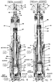
- Fig. 5 discloses the docking/shot assembly in the loaded and tilted position. In this position, both the docking piston 12 and shot piston 23 are retracted downwardly, this being accomplished by the proper operation of the valves V1, V2, V3, and V4.
- the valve V1 is subjected to pressurized fluid and controls the blocking of port or opening A and the introduction of pressurized fluid through or out of port or opening A.
- Valve V2 has the same control over the opening or port B while V3 has the same control over the port or opening C.
- Valve V4 controls the introduction of intensified pressurized fluid through the port or opening D.
- check valve 17 In the loaded and tilted position of Fig. 5 check valve 17 is closed by a spring action forcing the valve downwardly to close off the port or opening E.
- valve V1 is actuated to permit fluid to be metered out of the port or opening A
- valve V2 is still in the blocked position
- valve V3 is actuated to permit pressurized fluid to flow through the port C which exerts an upward pressure on the check valve 17 overcoming the spring bias so as to open the port E and permit pressurized fluid to flow into the lower chamber 13b.
- the next step in the sequence of operations is the actuation of the shot piston 23.
- This is accomplished by conditioning valve V1 to open, conditioning valve V2 to a metered out position, and continuing the flow of pressurized fluid through ports or openings C and E.
- Shot piston 23 is then forced upwardly by reason of the pressurized fluid in the upper chamber 24 of the docking piston being flowed out through the opening or port 16a, recess 16, and out of port or opening B.
- the docking piston continues to hold the injection sleeve in the gate 45 while the injectable metal in cavity 43 is forced by plunger tip 44 through the passageway 46 and into the cavity 6 of the die 5.
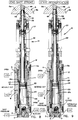
- Fig. 9 The next step in the sequence is illustrated by Fig. 9 wherein intensified pressurized fluid is introduced through the port or opening D by means of conditioning valve V4.
- valves V1, V2, and V3 remain in the same condition as in Fig. 8.
- check valve 17 shuttles and is closed due to the pressure differential on its top and bottom surfaces.
- the intensified pressure on shot piston 23 causes it to be forced upwardly a slight distance as illustrated by a comparison of the chambers 13a in Figs. 8 and 9. This additional movement assures that all of the injectable metal is injected into cavity 6 formed by cavity portions 6a and 6b to completely fill cavity 6.
- Fig. 10 illustrates the next step in the sequence which is to begin undocking of the injection sleeve 39. This is accomplished by conditioning valve V1 to permit pressurized fluid to flow through the port or opening A into the upper chamber 13a of the docking cylinder 11. At the same time, valve V2 is conditioned to block any exit of fluid from the opening or port B. The pressurized fluid in upper chamber 13a forces the docking piston downwardly to the position as disclosed in Fig. 10 while valve V3 is blocked and valve V4 is open to permit the flow of fluid in the lower chamber 13b to flow out of the opening or port D.
- valve V2 When the docking piston reaches the lowermost position, as disclosed in Fig. 10, valve V2 is conditioned to cause pressurized fluid to flow through the opening or port B into the recess 16 and through the opening 16a to the upper chamber 24 of the docking piston. At the same time, valve V1 is still admitting pressurized fluid into the upper chamber 13a of the outer docking cylinder 11 and valve V4 is open to permit flow of fluid out of the opening D while the port C is closed by valve V3. This mode in the operation is disclosed in Fig. 11.
- the docking/shot assembly as above described can be utilized in a vertical/vertical die casting machine wherein both the clamping mechanism and the docking/shot assembly are both vertically oriented, and in fact, the docking shot assembly can possibly be used in other die casting apparatus.
- the invention has been described in terms of a specific preferred embodiment, it should be understood that various modifications may be made within the scope and spirit of the invention.
Landscapes
- Engineering & Computer Science (AREA)
- Mechanical Engineering (AREA)
- Injection Moulding Of Plastics Or The Like (AREA)
- Moulds For Moulding Plastics Or The Like (AREA)
Applications Claiming Priority (2)
| Application Number | Priority Date | Filing Date | Title |
|---|---|---|---|
| US606331 | 1996-02-23 | ||
| US08/606,331 US5632321A (en) | 1996-02-23 | 1996-02-23 | Die casting machine with compound docking/shot cylinder |
Publications (2)
| Publication Number | Publication Date |
|---|---|
| EP0791418A2 true EP0791418A2 (de) | 1997-08-27 |
| EP0791418A3 EP0791418A3 (de) | 1998-02-25 |
Family
ID=24427545
Family Applications (1)
| Application Number | Title | Priority Date | Filing Date |
|---|---|---|---|
| EP97300679A Ceased EP0791418A3 (de) | 1996-02-23 | 1997-02-04 | Druckgussmaschine mit kombiniertem Positionier- und Pressdruckzylinder |
Country Status (3)
| Country | Link |
|---|---|
| US (1) | US5632321A (de) |
| EP (1) | EP0791418A3 (de) |
| CA (1) | CA2196328A1 (de) |
Cited By (2)
| Publication number | Priority date | Publication date | Assignee | Title |
|---|---|---|---|---|
| CN102700066A (zh) * | 2012-05-29 | 2012-10-03 | 苏州市欣龙塑胶模具有限公司 | 一种双层中空螺旋管模 |
| CN102717483A (zh) * | 2012-05-29 | 2012-10-10 | 苏州市欣龙塑胶模具有限公司 | 一种支架式塑胶模 |
Families Citing this family (8)
| Publication number | Priority date | Publication date | Assignee | Title |
|---|---|---|---|---|
| US6474399B2 (en) * | 1998-03-31 | 2002-11-05 | Takata Corporation | Injection molding method and apparatus with reduced piston leakage |
| DE19833504C2 (de) * | 1998-07-24 | 2000-05-04 | Gneuss Kunststofftechnik Gmbh | Kunststoffschmelze-Schußkolben |
| EP1057560A1 (de) * | 1999-06-01 | 2000-12-06 | Oskar Frech Gmbh & Co. | Einpressaggregat für eine Druckgiessmaschine |
| CN103384574B (zh) * | 2010-12-29 | 2016-02-10 | 艾维和阿鲁景观和机器人技术公司 | 压铸机和方法 |
| CN102717482A (zh) * | 2012-05-29 | 2012-10-10 | 苏州市欣龙塑胶模具有限公司 | 一种三层螺旋式塑胶模 |
| DE102012010923A1 (de) * | 2012-06-04 | 2013-12-05 | Gebr. Krallmann Gmbh | Fördervorrichtung für eine Metallschmelze in einem Spritzdruckaggregat |
| DE102014018797A1 (de) * | 2014-12-19 | 2016-06-23 | Gebr. Krallmann Gmbh | Fördervorrichtung für eine Metallschmelze in einem Spritzdruckaggregat |
| US20240149334A1 (en) * | 2022-11-08 | 2024-05-09 | Subaru Corporation | Plunger rod, injection device, injection method, concentricity measurement tool, and concentricity measurement method |
Family Cites Families (20)
| Publication number | Priority date | Publication date | Assignee | Title |
|---|---|---|---|---|
| US3344848A (en) * | 1963-06-24 | 1967-10-03 | Gen Motors Corp | Die casting apparatus with non-turbulent fill and dual shot plunger arrangement |
| US3605871A (en) * | 1969-05-01 | 1971-09-20 | Richard K Whitehead Sr | Die casting machine including sequentially acting compound pistion assembly machine |
| US4088178A (en) * | 1977-02-03 | 1978-05-09 | Ube Industries, Ltd. | Vertical die casting machines |
| CA1149579A (en) * | 1979-07-26 | 1983-07-12 | Toyoaki Ueno | Vertical die casting machine |
| JPS5913941B2 (ja) * | 1980-03-27 | 1984-04-02 | 宇部興産株式会社 | 横型締,竪鋳込型ダイカスト法および装置 |
| US4655274A (en) * | 1984-10-26 | 1987-04-07 | Ube Industries, Ltd. | Horizontal mold clamping and vertical injection type die cast machine |
| JPS62134155A (ja) * | 1985-12-06 | 1987-06-17 | Ube Ind Ltd | 竪鋳込型ダイカストマシン |
| JPS62134156A (ja) * | 1986-02-14 | 1987-06-17 | Ube Ind Ltd | 竪鋳込型ダイカストマシン |
| DE3763015D1 (de) * | 1986-03-03 | 1990-07-12 | Ube Industries | Vertikale spritzgussmaschine. |
| JPH01157753A (ja) * | 1987-02-16 | 1989-06-21 | Teisan Ind:Kk | ダイキヤスト装置 |
| JPS63220965A (ja) * | 1987-03-06 | 1988-09-14 | Ube Ind Ltd | 横型締竪鋳込型ダイカスト方法およびその装置 |
| JPS63273559A (ja) * | 1987-05-01 | 1988-11-10 | Ube Ind Ltd | 崩壊性置中子を用いた圧力鋳造方法 |
| US4741379A (en) * | 1987-07-08 | 1988-05-03 | Ube Industries, Ltd. | Horizontal mold clamping and verticle injection type injection molding machine |
| JPH0667545B2 (ja) * | 1988-06-10 | 1994-08-31 | 宇部興産株式会社 | 射出成形機 |
| JPH0661602B2 (ja) * | 1988-07-26 | 1994-08-17 | 宇部興産株式会社 | 射出成形機 |
| EP0381106B1 (de) * | 1989-01-30 | 1994-04-13 | Ube Industries, Ltd. | Einspritzvorrichtung |
| CA1335623C (en) * | 1989-03-21 | 1995-05-23 | Guido Perrella | Die casting machine |
| CA2019444C (en) * | 1989-06-23 | 1995-05-16 | Toyoaki Ueno | Method and apparatus for automatically supplying molten metal for die casting machine |
| JP2652582B2 (ja) * | 1990-03-27 | 1997-09-10 | 宇部興産株式会社 | 竪型ダイカストマシンとそのドッキング方法 |
| CA2083082C (en) * | 1992-11-17 | 2003-09-09 | Guido Perrella | Cold chamber die casting machine injection system |
-
1996
- 1996-02-23 US US08/606,331 patent/US5632321A/en not_active Expired - Fee Related
-
1997
- 1997-01-29 CA CA002196328A patent/CA2196328A1/en not_active Abandoned
- 1997-02-04 EP EP97300679A patent/EP0791418A3/de not_active Ceased
Cited By (2)
| Publication number | Priority date | Publication date | Assignee | Title |
|---|---|---|---|---|
| CN102700066A (zh) * | 2012-05-29 | 2012-10-03 | 苏州市欣龙塑胶模具有限公司 | 一种双层中空螺旋管模 |
| CN102717483A (zh) * | 2012-05-29 | 2012-10-10 | 苏州市欣龙塑胶模具有限公司 | 一种支架式塑胶模 |
Also Published As
| Publication number | Publication date |
|---|---|
| EP0791418A3 (de) | 1998-02-25 |
| US5632321A (en) | 1997-05-27 |
| CA2196328A1 (en) | 1997-08-24 |
Similar Documents
| Publication | Publication Date | Title |
|---|---|---|
| US5632321A (en) | Die casting machine with compound docking/shot cylinder | |
| US5728410A (en) | System for injection molding of plastic article utilizing a variable volume spill cavity | |
| US4287935A (en) | Vertical die casting machine | |
| JPH0615709A (ja) | 射出成形機用型締機構 | |
| US6953079B2 (en) | Die casting machine | |
| EP0426096A2 (de) | Rotationsmaschine zum Spritz-Streck-Blasformen | |
| US5601136A (en) | Inclined die cast shot sleeve system | |
| US4660620A (en) | Arrangement for controlling an injection process of a die casting machine | |
| EP0311269A1 (de) | Formklemmvorrichtung | |
| US4443179A (en) | Rapid-action mold closer | |
| EP1598130A1 (de) | Druckgussvorrichtung | |
| JP7727967B2 (ja) | ダイカスト製造方法及び装置並びに加圧手段 | |
| US5674541A (en) | Mold closing unit | |
| US20020160070A1 (en) | Mold clamping unit and injection molding apparatus | |
| US5284201A (en) | Vertical shot mechanism for die casting machine | |
| US5730204A (en) | Multishot die casting apparatus | |
| JP2024177576A (ja) | 加圧ロッドの動作制御方法、ダイカスト法 | |
| JP2009101420A (ja) | 成型装置 | |
| US5701944A (en) | Die casting machine and method | |
| KR102354707B1 (ko) | 사형 경동 주조 장치 및 방법 | |
| KR20230158865A (ko) | 씨피엠 공법에서의 대용량 가압 배기구조 | |
| EP0665093A1 (de) | Vorrichtung und Verfahren zum Formspannen | |
| JP2678961B2 (ja) | 竪型射出装置 | |
| JPH03151155A (ja) | 真空ダイカスト装置 | |
| JPH0733040B2 (ja) | 射出成形機及びガス供給装置 |
Legal Events
| Date | Code | Title | Description |
|---|---|---|---|
| PUAI | Public reference made under article 153(3) epc to a published international application that has entered the european phase |
Free format text: ORIGINAL CODE: 0009012 |
|
| AK | Designated contracting states |
Kind code of ref document: A2 Designated state(s): AT BE CH DE DK ES FI FR GB GR IE IT LI LU MC NL PT SE |
|
| PUAL | Search report despatched |
Free format text: ORIGINAL CODE: 0009013 |
|
| AK | Designated contracting states |
Kind code of ref document: A3 Designated state(s): AT BE CH DE DK ES FI FR GB GR IE IT LI LU MC NL PT SE |
|
| 17P | Request for examination filed |
Effective date: 19980806 |
|
| 17Q | First examination report despatched |
Effective date: 19981013 |
|
| GRAG | Despatch of communication of intention to grant |
Free format text: ORIGINAL CODE: EPIDOS AGRA |
|
| STAA | Information on the status of an ep patent application or granted ep patent |
Free format text: STATUS: THE APPLICATION HAS BEEN REFUSED |
|
| 18R | Application refused |
Effective date: 19991106 |