EP0791502A2 - Feu arrière pour véhicule - Google Patents
Feu arrière pour véhicule Download PDFInfo
- Publication number
- EP0791502A2 EP0791502A2 EP97102637A EP97102637A EP0791502A2 EP 0791502 A2 EP0791502 A2 EP 0791502A2 EP 97102637 A EP97102637 A EP 97102637A EP 97102637 A EP97102637 A EP 97102637A EP 0791502 A2 EP0791502 A2 EP 0791502A2
- Authority
- EP
- European Patent Office
- Prior art keywords
- lamp
- holding
- lamp holder
- holder
- indentation
- Prior art date
- Legal status (The legal status is an assumption and is not a legal conclusion. Google has not performed a legal analysis and makes no representation as to the accuracy of the status listed.)
- Granted
Links
Images

Classifications
-
- B—PERFORMING OPERATIONS; TRANSPORTING
- B60—VEHICLES IN GENERAL
- B60Q—ARRANGEMENT OF SIGNALLING OR LIGHTING DEVICES, THE MOUNTING OR SUPPORTING THEREOF OR CIRCUITS THEREFOR, FOR VEHICLES IN GENERAL
- B60Q1/00—Arrangement of optical signalling or lighting devices, the mounting or supporting thereof or circuits therefor
- B60Q1/26—Arrangement of optical signalling or lighting devices, the mounting or supporting thereof or circuits therefor the devices being primarily intended to indicate the vehicle, or parts thereof, or to give signals, to other traffic
- B60Q1/2607—Arrangement of optical signalling or lighting devices, the mounting or supporting thereof or circuits therefor the devices being primarily intended to indicate the vehicle, or parts thereof, or to give signals, to other traffic comprising at least two indicating lamps
-
- F—MECHANICAL ENGINEERING; LIGHTING; HEATING; WEAPONS; BLASTING
- F21—LIGHTING
- F21S—NON-PORTABLE LIGHTING DEVICES; SYSTEMS THEREOF; VEHICLE LIGHTING DEVICES SPECIALLY ADAPTED FOR VEHICLE EXTERIORS
- F21S43/00—Signalling devices specially adapted for vehicle exteriors, e.g. brake lamps, direction indicator lights or reversing lights
- F21S43/10—Signalling devices specially adapted for vehicle exteriors, e.g. brake lamps, direction indicator lights or reversing lights characterised by the light source
- F21S43/19—Attachment of light sources or lamp holders
- F21S43/195—Details of lamp holders, terminals or connectors
Definitions
- the invention relates to a rear lamp for vehicles, with at least two lamp chambers, in each of which a lamp holder for a first or second lamp is inserted, which have at least one filament and longitudinal axis extending transversely to the light exit direction of the respective lamp chamber and in which the outer surface of a base two retaining cams protrude, which are on both sides of the base facing away from both lamps, with a line running perpendicular to the filament passing through the two holding cams in the first lamp and a line running perpendicular to the filament passing through the second lamp and the other passing through the second lamp Holding cams is spaced from the line, and which engage in a first or second indentation of the respective lamp holder, which adjoins the outer surface of the base with holding lugs protruding from an opening.
- a rear light for vehicles with a single light chamber has become known from German utility model U 72 15 851.
- a plate-shaped lamp holder for a first lamp made of sheet metal is inserted into the lamp chamber.
- the main extension of the plate-shaped lamp holder extends in the direction of light emission and is connected to the lamp housing by a bracket.
- the holder has facing guide slots into which the lamp holder is inserted and screws that hold the lamp holder on the lamp housing.
- the two retaining tabs which protrude from the opening and which adjoin the cylindrical outer surface of the base of the first lamp have, at their free end section, an outwardly open first indentation for a retaining cam of the first lamp.
- the opening of the lamp holder tightly surrounds the cylindrical base and has two diametrically opposed cutouts at its edge.
- the cutouts serve to lead the two holding cams of the first lamp through.
- a center pole of the first lamp lies one on the lamp housing held electrical contact spring under tension and presses the holding cams of the first lamp into the indentations of the holding tabs.
- the lamp holder can also be attached to the luminaire housing by 180 degrees so that the retaining tabs point away from the electrical contact spring.
- the holding cams of the first lamp then engage in indentations which are introduced between the holding tabs in the edge of the opening of the lamp holder.
- the lamp can thus be inserted into the lamp holder from one side and the other, and can also be held on the lamp holder in two positions rotated by 90 degrees. Since the filament of the first lamp extends transversely to the light exit direction in both positions, the lamp holder is inserted transversely to the filament in the one position and in the light housing in the other position in the direction of the filament.
- a reflector In a rear light for vehicles, which is known from the German utility model U 73 21 153, a reflector carries on its back a lamp holder made of sheet metal, which is inserted into the slots of the reflector in a self-locking manner with fastening tabs. Barb-like clamping teeth dig into the inside of the respective slot.
- the holding tabs protruding from the opening of the lamp holder protrude into the opening of the reflector and each have an opening with an indentation between their end sections.
- the holding cams of the first lamp engage in the indentations and are inserted into the lamp holder from the inside of the reflector.
- a flashing light used in practice for vehicles with several light chambers has become known, in which a first or second lamp is inserted into a separate lamp holder.
- the lamp holders for the first and second lamps are designed differently and either have the first indentations for the two retaining cams of the first lamp or a first and second indentation for the second lamp. Since a differently designed lamp holder is used for the first and second lamp, not only is extensive storage required for the lamp holder, but also different tools for producing the lamp holder are required.
- the object of the invention is to design the rear lamp for vehicles described in the preamble of claim 1 in such a way that a largely uniform structure for the lamp chambers accommodating the first and second lamp is possible by a simple design of the lamp holder in order to mount the rear lamp quickly and easily and to be able to manufacture inexpensively.
- the lamp holder for the first and second lamp are identical in their construction and on the free and / or in the region of the end section of the holding tab connected to the lamp holder an outwardly open first indentation for the two holding cams of the first lamp, wherein a holding cam of the second lamp engages in one of the first indentations and the other holding cam engages in a second indentation which has a holding tab between its end sections.
- the second lamp cannot be inserted into the lamp holder in two positions from one side if a second indentation is only introduced into one of the two retaining tabs. If the lamp holders each have an indentation in the region of the end sections connected to the lamp holder and the free end sections of the retaining tabs, the first lamp can be inserted into the opening from both sides of the lamp holder. In addition, the second lamp can be inserted into the opening from both sides of the lamp holder if the second indentation in the retaining tab of the lamp holder is designed accordingly.
- the lamp holders can be fixed in the same way in the lamp chambers if the lamp holders are inserted into holders of the lamp which are identical in their construction. This is particularly advantageous in the case of automatic production.
- the rear light can be used for mounting on both the right and left side of the vehicle if a holder is arranged in both the upper and lower half of the lamp chambers in several lamp chambers for the first or second lamp when the lamp is in the installed position. In one rear light version, the lamp holder must be inserted in the lower half of the light chambers, while in the other rear light version, the lamp holders are to be inserted in the upper half of the light chambers.
- brackets for the lamp holder In a luminaire housing made of plastic, which is covered by a cover plate, there is no need for additional adjustable tool parts to manufacture the brackets for the lamp holder if the brackets are formed by projections molded onto the bottom of the luminaire housing, each of which has a side facing it Have light exit direction of the respective luminaire chamber extending guide slot for the lamp holder.
- the lamp brackets can be installed quickly and easily if the lamp brackets consist of a plate-shaped rectangular sheet, the main extension of which extends in the light exit direction of the respective luminaire chamber and is self-locking and / or self-locking in the guide slots of the brackets.
- the lamp supports have at least one clamping lug pressed out and / or at least one clamping tooth cut out of the side edges and bent out on the side edges facing away from one another.
- a lamp holder is simple in design and can be fixed very securely in the guide slots.
- the lamp holder can be easily and quickly connected to electrical lines if a flat plug connection is cut out of the lamp holders and / or the lamp holders have an outwardly open slot which serves as an insulation displacement device for electrical cables, the long side edges being the cut edges for are the sheath of the cable and serve to clamp the cable.
- the insulation displacement device the automatic electrical contact to the cables can be made automatically when the lamp holder is inserted into the lamp chambers.
- the first indentations for the holding cams of the first lamp are simple in design if they are formed in the region of the end section of the holding tabs connected to the lamp holder from the inside of a depressed depression and / or a hole. It is particularly advantageous here if the second indentation is formed by a franking introduced into a side edge of a retaining tab, which extends towards the end section connected to the lamp holder and the edge of the opening, one in the edge of the opening Opening depressed recess adjoins the franking of one retaining tab, while a hole is made in the other retaining tab.
- a holding tab of the lamp holder has a clearing with two second indentations lying side by side, in each of which a holding cam of different second lamps engages, both of which engage with the other holding cam in one of the first indentations.
- both first lamps and two differently designed second lamps can be used in the lamp holder. Either only the first or second lamp can be inserted into the lamp holder in a lamp chamber if at least one recess in the lamp holder, which is made between the retaining tabs in the edge region of the opening of the lamp holder and is used to pass a retaining cam of the first or second lamp , is closed by a projection of the lamp housing. As a result, only the lamp intended for them can be inserted into the lamp holder in each lamp chamber.
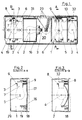
- the rear light for vehicles has a rectangular shape and, in the installed position, has several light compartments (1 or 2) lying side by side.
- the lamp chambers (1 and 2) lie side by side and are formed by a lamp housing (18) and a translucent cover plate (29) which closes the lamp housing (18).
- three lamp chambers (2) with a first lamp (4) and a lamp chamber (1) with a second lamp (5) are shown.
- the first lamps (4) have a single filament (6) and the second lamp (5) has two filaments (6).
- the three lamp chambers (2) with the first lamps (4) serve as indicators, additional reversing lamps or rear fog lamps and the lamp chamber (1) with the second lamp (5) serves as a tail and brake lamp.
- a lamp holder (3) is inserted into each of the lamp chambers (1 and 2).
- All lamp holders (3) of the rear light are made with the same tool.
- the first and second lamps (4 and 5) are inserted into an opening (12) in the lamp holder (3).
- the incandescent filament (6) of the lamps (4 and 5) run transversely to their longitudinal axis and the longitudinal axis and the incandescent filament (6) run transversely to the light exit direction of the respective luminaire chamber (1 or 2).
- the lamp holder (3) is made of sheet metal and has a rectangular shape. Arranged on the long side edges of the rectangular lamp holder (3) are two pressed-out clamping nipples (20) and a clamping tooth (21) cut free between them and bent out of the lamp holder.
- the lamp chambers (1 and 2) are provided with holders (16) for the lamp holder (3) which are identical in their construction.
- the mounts (16) on the inside of the base (17) of the luminaire housing (18) are molded lugs with facing guide slots (19).
- the plate-shaped, Rectangular lamp holder (3) inserted upright.
- the lamp carrier (3) is securely fixed in the guide slots (19) by the clamping lugs (20) and the clamping teeth (21).
- the lamp holder (3) has a tab connector (22) and a slot (24) on the side edge adjacent to the bottom (17) of the lamp housing (18).
- the tab connector (22) is cut out of the lamp holder (3) and bent out of it, while the slot (24) is punched out of the lamp holder (3).
- the lamp holder (3) can be connected to an electrical line via the flat plug connection (22) or the slot (24).
- cables (23) serve as electrical lines, which automatically clamp in the slot (24) when the lamp holder (3) is inserted into the guide slots (19).
- the slot (24) serves as an insulation displacement device, since the side edges of the slot (24) cut through an elastic jacket of the cable (23) and clamp the core of the cable (23) between them.
- the cables (23) run from the individual lamp chambers (1 and 2) to a space (30) between two lamp chambers (1 and 2). In the room (30), the cables (23) are led out through the floor (17) of the lamp housing (18).
- the lamp chamber (2) adjoining the room (30) serves as an additional reversing light and is sealed off from the other lamp chambers to such an extent that the lamp chamber (2) is not disruptively illuminated by the light from the neighboring lamp chambers.
- the lamp holder (3) is arranged towards the adjacent room (30) for the lamp chamber (2) and the lamp holder (2) is limited to the lamp holder (3) by a peripheral side wall (31).
- the lamp holders (3) and their holders (16) are arranged in the upper half of the lamp chambers (1 and 2), the lamps (4 and 5) pointing downwards with their glass bulbs.
- the lamp halves (1 and 2) also have a holder (16) for the lamp holder (3) in their lower half. The rear light can thus be mounted on the left or right side of the vehicle, depending on whether the lamp holder (3) is inserted into the brackets (16) arranged above or below.
- the first and second lamps (4 and 5) each have a protruding retaining cam (8 and 9) on opposite sides of their cylindrical base (7).
- first lamp (4) one passes vertically through the two holding cams (8) the line going along the longitudinal axis of the lamp (4) and running perpendicular to the filament (6).
- second lamp (5) shown in FIGS. 1 and 2 which has two incandescent filaments (6), a line running perpendicularly through the longitudinal axis of the lamp (5) and perpendicular to the incandescent filaments (6) passes through both holding cams (9) , the two lines being spaced apart.
- the lamp holder (3) shown in FIGS. 4, 5, 6 and 7 has holding tabs (13) which are bent out of its opening (12) and which have the inside of them on the lateral surface of the cylindrical base (7) of the lamp (4 and 5 ) issue.
- a first indentation (10) is made in the area of the end sections (15) connected to the lamp holder (3).
- One of the first indentations (10) is a depression which is pressed into the edge region of the opening (12) and which adjoins the franking (25), while the other first indentation (10) is introduced by a between the end section (15) and the lamp holder (3) Hole is formed.
- diametrically opposite recesses (26) and a recess (27) are made in the edge of the circular opening (12) in the edge of the circular opening (12) diametrically opposite recesses (26) and a recess (27) are made.
- the recesses (26) serve to pass the holding cams (8) of the first lamp (4), while the recess (27) serves to pass one of the two holding cams (9) of the second lamp (5).
- the lamps (4 and 5) are inserted from the side into the lamp holder (3) on which the retaining tabs (13) are arranged.
- the holding cams (8) of the first lamp (4) engage in the first indentations (10) of the lamp holder (3).
- the second lamp (5) is inserted into the lamp holder (3), one of the two holding cams (9) is passed through the recess (27) and after the second lamps (5) have been turned counterclockwise, one of the two holding cams (9) engages. into one of the two first indentations (10) and the other holding cam (9) into the second indentation (11) of the holding flap (13).
- an electrical contact spring (32) rests against an electrical pole on the top surface of the cylindrical base (7) of the first lamp (4) under prestress and presses the two holding cams (8) into the first indentations (10) into it.
- one of the electrical contact springs (32) bears against two electrical poles on the top surface of the cylindrical base (7) under prestress and presses the one holding cam (9) against one of the two first indentations (10) and the other against the second indentation (11).
- a projection (28) is shown in dashed lines.
- the projection (28) is integrally formed in the lamp chambers (2) on the housing (18) and closes the recess (27) in the lamp holder (3).
- the second lamp (5) cannot be inadvertently inserted into the lamp holder (3) in the lamp chambers (2).
- At least one of the two cutouts (26) in the lamp chamber (1) is closed by a projection (28).
- FIG. 8 shows a second embodiment of the lamp holder (3).
- the second lamp (5) and a lamp (5) described above can be used in the lamp holder (3), in which one of the holding cams (9) engages in one of the first indentations (10) and the second holding cam (9) in one of two second indentations (11), which are formed laterally side by side by a clearance (25) in one of the two retaining tabs (13).
- a first and second lamp (4 and 5) can be inserted into the lamp holder (3) both from one side and from the other side, since this lamp is located both in the area of the lamp holder (3 ) connected end section (15) and the free end section (14) has a first indentation (10) and in one of the retaining tabs (13) has a clearing (25) with facing indentations (11).
Landscapes
- Engineering & Computer Science (AREA)
- Mechanical Engineering (AREA)
- General Engineering & Computer Science (AREA)
- Lighting Device Outwards From Vehicle And Optical Signal (AREA)
- Non-Portable Lighting Devices Or Systems Thereof (AREA)
- Fastening Of Light Sources Or Lamp Holders (AREA)
Applications Claiming Priority (2)
| Application Number | Priority Date | Filing Date | Title |
|---|---|---|---|
| DE29603432U | 1996-02-24 | ||
| DE29603432U DE29603432U1 (de) | 1996-02-24 | 1996-02-24 | Heckleuchte für Fahrzeuge |
Publications (3)
| Publication Number | Publication Date |
|---|---|
| EP0791502A2 true EP0791502A2 (fr) | 1997-08-27 |
| EP0791502A3 EP0791502A3 (fr) | 1998-12-02 |
| EP0791502B1 EP0791502B1 (fr) | 2001-10-24 |
Family
ID=8020088
Family Applications (1)
| Application Number | Title | Priority Date | Filing Date |
|---|---|---|---|
| EP97102637A Expired - Lifetime EP0791502B1 (fr) | 1996-02-24 | 1997-02-19 | Feu arrière pour véhicule |
Country Status (3)
| Country | Link |
|---|---|
| EP (1) | EP0791502B1 (fr) |
| DE (2) | DE29603432U1 (fr) |
| ES (1) | ES2166482T3 (fr) |
Cited By (3)
| Publication number | Priority date | Publication date | Assignee | Title |
|---|---|---|---|---|
| EP1036705A3 (fr) * | 1999-03-18 | 2004-03-03 | Hella KG Hueck & Co. | Feux de véhicule |
| RU2288114C2 (ru) * | 2004-09-07 | 2006-11-27 | Открытое акционерное общество "АВТОВАЗ" | Задний фонарь транспортного средства |
| RU2406923C1 (ru) * | 2009-12-28 | 2010-12-20 | Федеральное государственное учреждение "21 научно-исследовательский испытательный институт Минобороны России" | Фонарь светомаскировочный задний |
Families Citing this family (2)
| Publication number | Priority date | Publication date | Assignee | Title |
|---|---|---|---|---|
| FR2903760B1 (fr) * | 2006-07-13 | 2010-12-31 | Valeo Vision | Support decoupe inverse apte a maintenir une douille de source lumineuse de dispositif projecteur. |
| JP6195505B2 (ja) * | 2013-11-19 | 2017-09-13 | 株式会社小糸製作所 | ドアハンドル |
Family Cites Families (11)
| Publication number | Priority date | Publication date | Assignee | Title |
|---|---|---|---|---|
| DE7125867U (de) * | 1972-03-16 | Hueck & Co | Fahrzeugleuchte | |
| DE7215851U (de) * | 1973-01-04 | Westfaelische Metall Ind Kg | Leuchte, insbesondere für Fahrzeuge | |
| US1682948A (en) * | 1925-07-13 | 1928-09-04 | Woller Oliver C Ritz | Warning light |
| DE7321153U (fr) * | 1973-06-06 | 1974-02-21 | Hueck & Co Kg | |
| DE2602237C3 (de) * | 1976-01-22 | 1979-01-04 | Westfaelische Metall Industrie Kg, Hueck & Co, 4780 Lippstadt | Mehrkammerleuchte für Fahrzeuge |
| DE2746449C3 (de) * | 1977-10-15 | 1980-09-11 | Westfaelische Metall Industrie Kg, Hueck & Co, 4780 Lippstadt | Fahrzeugleuchte |
| US4423915A (en) * | 1982-02-22 | 1984-01-03 | Chrysler Corporation | Lamp socket |
| DE3220456C2 (de) * | 1982-05-29 | 1987-04-09 | Reitter & Schefenacker Kg, 7300 Esslingen | Lampenträger für Glühlampen einer Kraftfahrzeugleuchte |
| DE3342382A1 (de) * | 1983-11-24 | 1985-06-05 | SWF Auto-Electric GmbH, 7120 Bietigheim-Bissingen | Fahrzeugleuchte mit einer oder mehreren gluehlampen |
| DE3416469A1 (de) * | 1984-05-04 | 1985-11-07 | Ulo-Werk Moritz Ullmann Gmbh & Co Kg, 7340 Geislingen | Lampenfassung, insbesondere fuer kraftfahrzeugleuchten |
| DE8910043U1 (de) * | 1989-08-22 | 1989-10-05 | Hella KG Hueck & Co, 4780 Lippstadt | Mehrkammerleuchte |
-
1996
- 1996-02-24 DE DE29603432U patent/DE29603432U1/de not_active Expired - Lifetime
-
1997
- 1997-02-19 ES ES97102637T patent/ES2166482T3/es not_active Expired - Lifetime
- 1997-02-19 DE DE59705016T patent/DE59705016D1/de not_active Expired - Lifetime
- 1997-02-19 EP EP97102637A patent/EP0791502B1/fr not_active Expired - Lifetime
Cited By (3)
| Publication number | Priority date | Publication date | Assignee | Title |
|---|---|---|---|---|
| EP1036705A3 (fr) * | 1999-03-18 | 2004-03-03 | Hella KG Hueck & Co. | Feux de véhicule |
| RU2288114C2 (ru) * | 2004-09-07 | 2006-11-27 | Открытое акционерное общество "АВТОВАЗ" | Задний фонарь транспортного средства |
| RU2406923C1 (ru) * | 2009-12-28 | 2010-12-20 | Федеральное государственное учреждение "21 научно-исследовательский испытательный институт Минобороны России" | Фонарь светомаскировочный задний |
Also Published As
| Publication number | Publication date |
|---|---|
| EP0791502A3 (fr) | 1998-12-02 |
| ES2166482T3 (es) | 2002-04-16 |
| DE29603432U1 (de) | 1996-04-18 |
| DE59705016D1 (de) | 2001-11-29 |
| EP0791502B1 (fr) | 2001-10-24 |
Similar Documents
| Publication | Publication Date | Title |
|---|---|---|
| DE19506365C2 (de) | Verbinderbefestigungsanordnung | |
| DE102007022028B4 (de) | Beleuchtungseinrichtung für ein Fahrzeug, insbesondere Kraftfahrzeugscheinwerfer | |
| DE4113559A1 (de) | Verbinder-einbauanordnung | |
| DE4036031C1 (fr) | ||
| EP0791502B1 (fr) | Feu arrière pour véhicule | |
| EP0141021A2 (fr) | Douille pour lampe à incandescence | |
| DE4026945C2 (de) | Heckleuchte für ein Kraftfahrzeug | |
| DE2013542A1 (fr) | ||
| DE4406393A1 (de) | Scheinwerfer-Leuchteneinheit für Fahrzeuge | |
| DE3342382C2 (fr) | ||
| EP2131102A1 (fr) | Lampe à poutres | |
| EP0060900A1 (fr) | Bloc optique compartimenté pour véhicule | |
| DE10100605B4 (de) | Elektrische Beleuchtungsvorrichtung mit einer punktförmigen Lichtquelle | |
| DE69623215T2 (de) | Träger zum Befestigen einer Beleuchtungsvorrichtung an einer Mauer und dazu geeignete Beleuchtungsvorrichtung | |
| DE19603375C2 (de) | Platzsparende Fassung | |
| DE4106322C2 (de) | Beleuchtungseinrichtung für einen elektrischen Zigarrenanzünder | |
| DE3611813A1 (de) | Elektrische leuchte | |
| DE3151500A1 (de) | Fahrzeugleuchte mit mehreren gluehlampen | |
| EP0392198A1 (fr) | Armature d'éclairage de forme allongée | |
| EP1047574A1 (fr) | Systeme d'eclairage pour vehicules | |
| EP0214424B1 (fr) | Support pour lampe électrique à incandescence avec culot à baionnette | |
| DE3044328C2 (de) | Kabelhalterung an einem Leuchtengehäuse | |
| EP1036705B1 (fr) | Feux de véhicule | |
| EP1337783A1 (fr) | Lampe dotee d'une plaque de recouvrement | |
| DE69837191T2 (de) | Leuchte |
Legal Events
| Date | Code | Title | Description |
|---|---|---|---|
| PUAI | Public reference made under article 153(3) epc to a published international application that has entered the european phase |
Free format text: ORIGINAL CODE: 0009012 |
|
| AK | Designated contracting states |
Kind code of ref document: A2 Designated state(s): DE ES FI FR GB IT |
|
| PUAL | Search report despatched |
Free format text: ORIGINAL CODE: 0009013 |
|
| AK | Designated contracting states |
Kind code of ref document: A3 Designated state(s): DE ES FI FR GB IT |
|
| 17P | Request for examination filed |
Effective date: 19990412 |
|
| GRAG | Despatch of communication of intention to grant |
Free format text: ORIGINAL CODE: EPIDOS AGRA |
|
| 17Q | First examination report despatched |
Effective date: 20010112 |
|
| GRAG | Despatch of communication of intention to grant |
Free format text: ORIGINAL CODE: EPIDOS AGRA |
|
| GRAH | Despatch of communication of intention to grant a patent |
Free format text: ORIGINAL CODE: EPIDOS IGRA |
|
| ITF | It: translation for a ep patent filed | ||
| GRAH | Despatch of communication of intention to grant a patent |
Free format text: ORIGINAL CODE: EPIDOS IGRA |
|
| GRAA | (expected) grant |
Free format text: ORIGINAL CODE: 0009210 |
|
| RIC1 | Information provided on ipc code assigned before grant |
Free format text: 7B 60Q 1/26 A, 7F 21S 8/10 B, 7H 01R 33/46 B |
|
| AK | Designated contracting states |
Kind code of ref document: B1 Designated state(s): DE ES FI FR GB IT |
|
| PG25 | Lapsed in a contracting state [announced via postgrant information from national office to epo] |
Ref country code: FI Free format text: LAPSE BECAUSE OF FAILURE TO SUBMIT A TRANSLATION OF THE DESCRIPTION OR TO PAY THE FEE WITHIN THE PRESCRIBED TIME-LIMIT Effective date: 20011024 |
|
| REF | Corresponds to: |
Ref document number: 59705016 Country of ref document: DE Date of ref document: 20011129 |
|
| REG | Reference to a national code |
Ref country code: GB Ref legal event code: IF02 |
|
| GBT | Gb: translation of ep patent filed (gb section 77(6)(a)/1977) |
Effective date: 20020105 |
|
| ET | Fr: translation filed | ||
| REG | Reference to a national code |
Ref country code: ES Ref legal event code: FG2A Ref document number: 2166482 Country of ref document: ES Kind code of ref document: T3 |
|
| PLBE | No opposition filed within time limit |
Free format text: ORIGINAL CODE: 0009261 |
|
| STAA | Information on the status of an ep patent application or granted ep patent |
Free format text: STATUS: NO OPPOSITION FILED WITHIN TIME LIMIT |
|
| 26N | No opposition filed | ||
| PGFP | Annual fee paid to national office [announced via postgrant information from national office to epo] |
Ref country code: IT Payment date: 20060228 Year of fee payment: 10 |
|
| PGFP | Annual fee paid to national office [announced via postgrant information from national office to epo] |
Ref country code: ES Payment date: 20060317 Year of fee payment: 10 |
|
| GBPC | Gb: european patent ceased through non-payment of renewal fee |
Effective date: 20070219 |
|
| PG25 | Lapsed in a contracting state [announced via postgrant information from national office to epo] |
Ref country code: GB Free format text: LAPSE BECAUSE OF NON-PAYMENT OF DUE FEES Effective date: 20070219 |
|
| REG | Reference to a national code |
Ref country code: ES Ref legal event code: FD2A Effective date: 20070220 |
|
| PG25 | Lapsed in a contracting state [announced via postgrant information from national office to epo] |
Ref country code: ES Free format text: LAPSE BECAUSE OF NON-PAYMENT OF DUE FEES Effective date: 20070220 |
|
| PGFP | Annual fee paid to national office [announced via postgrant information from national office to epo] |
Ref country code: GB Payment date: 20060215 Year of fee payment: 10 |
|
| PG25 | Lapsed in a contracting state [announced via postgrant information from national office to epo] |
Ref country code: IT Free format text: LAPSE BECAUSE OF NON-PAYMENT OF DUE FEES Effective date: 20070219 |
|
| PGFP | Annual fee paid to national office [announced via postgrant information from national office to epo] |
Ref country code: FR Payment date: 20100223 Year of fee payment: 14 |
|
| REG | Reference to a national code |
Ref country code: FR Ref legal event code: ST Effective date: 20111102 |
|
| PG25 | Lapsed in a contracting state [announced via postgrant information from national office to epo] |
Ref country code: FR Free format text: LAPSE BECAUSE OF NON-PAYMENT OF DUE FEES Effective date: 20110228 |
|
| PGFP | Annual fee paid to national office [announced via postgrant information from national office to epo] |
Ref country code: DE Payment date: 20160216 Year of fee payment: 20 |
|
| REG | Reference to a national code |
Ref country code: DE Ref legal event code: R071 Ref document number: 59705016 Country of ref document: DE |