EP0791693A1 - Arbeitsfahrzeug - Google Patents
Arbeitsfahrzeug Download PDFInfo
- Publication number
- EP0791693A1 EP0791693A1 EP95936095A EP95936095A EP0791693A1 EP 0791693 A1 EP0791693 A1 EP 0791693A1 EP 95936095 A EP95936095 A EP 95936095A EP 95936095 A EP95936095 A EP 95936095A EP 0791693 A1 EP0791693 A1 EP 0791693A1
- Authority
- EP
- European Patent Office
- Prior art keywords
- boom
- pin
- arm
- attached
- end portion
- Prior art date
- Legal status (The legal status is an assumption and is not a legal conclusion. Google has not performed a legal analysis and makes no representation as to the accuracy of the status listed.)
- Granted
Links
Images


Classifications
-
- E—FIXED CONSTRUCTIONS
- E02—HYDRAULIC ENGINEERING; FOUNDATIONS; SOIL SHIFTING
- E02F—DREDGING; SOIL-SHIFTING
- E02F3/00—Dredgers; Soil-shifting machines
- E02F3/04—Dredgers; Soil-shifting machines mechanically-driven
- E02F3/28—Dredgers; Soil-shifting machines mechanically-driven with digging tools mounted on a dipper- or bucket-arm, i.e. there is either one arm or a pair of arms, e.g. dippers, buckets
-
- E—FIXED CONSTRUCTIONS
- E02—HYDRAULIC ENGINEERING; FOUNDATIONS; SOIL SHIFTING
- E02F—DREDGING; SOIL-SHIFTING
- E02F9/00—Component parts of dredgers or soil-shifting machines, not restricted to one of the kinds covered by groups E02F3/00 - E02F7/00
- E02F9/08—Superstructures; Supports for superstructures
- E02F9/0808—Improving mounting or assembling, e.g. frame elements, disposition of all the components on the superstructures
-
- E—FIXED CONSTRUCTIONS
- E02—HYDRAULIC ENGINEERING; FOUNDATIONS; SOIL SHIFTING
- E02F—DREDGING; SOIL-SHIFTING
- E02F3/00—Dredgers; Soil-shifting machines
- E02F3/04—Dredgers; Soil-shifting machines mechanically-driven
- E02F3/28—Dredgers; Soil-shifting machines mechanically-driven with digging tools mounted on a dipper- or bucket-arm, i.e. there is either one arm or a pair of arms, e.g. dippers, buckets
- E02F3/30—Dredgers; Soil-shifting machines mechanically-driven with digging tools mounted on a dipper- or bucket-arm, i.e. there is either one arm or a pair of arms, e.g. dippers, buckets with a dipper-arm pivoted on a cantilever beam, i.e. boom
- E02F3/301—Dredgers; Soil-shifting machines mechanically-driven with digging tools mounted on a dipper- or bucket-arm, i.e. there is either one arm or a pair of arms, e.g. dippers, buckets with a dipper-arm pivoted on a cantilever beam, i.e. boom with more than two arms (boom included), e.g. two-part boom with additional dipper-arm
-
- E—FIXED CONSTRUCTIONS
- E02—HYDRAULIC ENGINEERING; FOUNDATIONS; SOIL SHIFTING
- E02F—DREDGING; SOIL-SHIFTING
- E02F3/00—Dredgers; Soil-shifting machines
- E02F3/04—Dredgers; Soil-shifting machines mechanically-driven
- E02F3/28—Dredgers; Soil-shifting machines mechanically-driven with digging tools mounted on a dipper- or bucket-arm, i.e. there is either one arm or a pair of arms, e.g. dippers, buckets
- E02F3/36—Component parts
- E02F3/38—Cantilever beams, i.e. booms;, e.g. manufacturing processes, forms, geometry or materials used for booms; Dipper-arms, e.g. manufacturing processes, forms, geometry or materials used for dipper-arms; Bucket-arms
Definitions
- the present invention relates to a working vehicle, and particularly to a working vehicle having a working unit such as a bucket or the like ahead of the operator's seat.
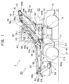
- a construction equipment 100 being one of working vehicles has a first boom 131a attached to a vehicle body frame 121, a second boom 131b attached to the first boom 131a, and an arm 132 attached to the second boom 131b, so as to be respectively free to swing.
- a working unit 130 having a bucket 133 and the like is attached to the arm 132.
- the bucket 133 in a traveling posture is stably placed on a bracket 115 fixed on the front portion of a base frame 111 and stably housed by hooking the front end portion of the bucket with a hooking device 116.
- the construction equipment 100 is provided with a first boom cylinder 135 attached to the vehicle body frame 121 and the second boom 131b and swinging the second boom 131b, a second boom cylinder 136 attached to the second boom 131b and the first boom 131a and swinging the second boom 131b, and an arm cylinder 137 attached to the second boom 131b and the arm 132 and swinging the arm 132.
- the vehicle body frame 121 and the fist boom 131a are connected by a pin 123
- the first boom 131a and the second boom 131b arc connected by a pin 141
- the vehicle body frame 121 and the first boom cylinder 135 are connected by a pin 124
- the second boom 131b and the first boom cylinder 135 are connected by a pin 143.
- the pin 124 is positioned near one end portion of the line and the pin 143 is positioned near the other end portion of the line.
- the above-described construction equipment 100 has increased front overhang amount 112 and greater rotation radius.
- a height of housing posture 113 of the arm 132 and the arm cylinder 137 becomes great, therefore there is a disadvantage of low visibility of the lower part on the right side in front.
- a construction equipment 110 illustrated in Fig. 5 is known.
- the construction equipment 110 has a higher visibility of the side portion in a traveling posture with the working unit 130 being housed as compared to the construction equipment 100 in a housed posture.
- a height of housing posture 114 of the working unit 130 is high, the position of the center of gravity of the construction equipment 110 becomes high, and a disadvantage exists in the stability at the time of traveling at high speed.
- the present invention is made in order to eliminate the above-described disadvantages in the conventional art, and its object is to provide a working vehicle having high visibility and transportability, and a large excavating force over a wide range, with a working unit smoothly operated.
- the working vehicle relating to the present invention is a working vehicle provided with an upper rotary body on a base carrier with a working unit provided with a boom, an arm, and a bucket, and an operator's cab being respectively attached on said upper rotary body, characterized by the above-described working unit being a working unit provided with a boom divided into a first boom attached on a vehicle body frame and a second boom attached to said first boom by the medium of a second pin, an arm attached to a front end portion of the second boom by the medium of a seventh pin, and a bucket attached to a front end portion of the arm, the first boom being free to swing by a first boom cylinder attached to a sixth pin of the second boom and a fifth pin of the vehicle body frame, and the second boom being free to swing by a second boom cylinder attached to a third pin of the first boom and a fourth pin of a rear end portion of the second boom, and characterized by one end portion of a first arm link being attached to the second boom by the medium of a ten
- the length between the centers of the ninth pin and the tenth pin can be greater than the length between the centers of the eighth pin and the seventh pin.
- second boom housing section for housing the second boom is provided inside the first boom, and that at the time of traveling, the divided boom has the second boom housed in the second boom housing section.
- the arm is parallel to a top surface of a base frame of the base carrier with the arm cylinder being contracted, and that the posture of the working unit at the time of traveling is a housed posture in which the divided boom in a housed condition and the arm with the arm cylinder being contracted make almost V-shaped form.
- the second boom is rotated with the second pin as its fulcrum by contracting the rod of the second boom cylinder at the time of the operation from the hosing posture to the working posture.
- the first boom is rotated in a counterclockwise direction with the first pin as its fulcrum.
- the housing posture when the line connecting the centers of the first and second pins is a reference, the line connecting the centers of the first and the sixth pins has an angle in a counterclockwise direction, therefore a derricking operation is carried out smoothly.
- the divided boom is smoothly operated over extremely wide range by supplying an actuator oil to the second boom cylinder and the first boom cylinder.
- the rotation angle of the arm greater than the conventional art can be obtained relative to the stroke of the arm cylinder since the length between the centers of the ninth and tenth pins are made relatively greater.
- the radius of the rotation moment is greater than the conventional art, the excavating force at the edge of front end of the bucket is increased.
- the divided boom is in a compact housed posture since the second boom is housed by extending the second boom cylinder. Accordingly, since an operator in an operator's cab can obtain excellent visibility with the housing posture at the time of traveling, safety can be secured. Further, the arm at the time of being housed becomes almost parallel to the top surface of the base frame, and the arm and the divided boom are made to be almost in a V-shaped form. Thereby, excellent visibility can be obtained, while the center of gravity of the working unit is at a lower position, so that stability can be secured at the time of traveling at high speed.
- a working vehicle 1 includes a base carrier 10 and an upper rotary body 20 placed on the base carrier 10 so as to be free to rotate with the point close to a center of the base carrier 10 as its center of rotation CL.
- the working vehicle 1 also includes a working unit 30 which is placed on a vehicle body frame 21 on the upper rotary body 20 and which is free to derrick relative to the upper rotary body 20, and an operator's cab 60 for an operator 61 to sit in to operate the working unit 30.
- the base carrier 10 includes wheels 12 which are rotated by an oil hydraulic motor for running (not illustrated) equipped on a base frame 11 or the like and which run the working vehicle 1, and a rotation bearing 13 supporting the upper rotary body 20 positioned on the base frame 11.
- the wheels 12 can be an endless crawler belt.
- the upper rotary body 20 consists of the vehicle body frame 21 supported by the rotation bearing 13, and a rotary body cover 22 attached to the vehicle body frame 21 and including a counter weight 22a.
- the upper rotary body 20 is installed so as to be free to rotate in a horizontal direction relative to the center of rotation CL located almost at the center of the base frame 11 both in a width direction and in a fore-and-aft direction, and the upper rotary body 20 is rotated by an oil hydraulic motor for rotation (not illustrated) actuated by the operation of the operator 61 in the operator's cab 60.
- a first pin 23 supporting the working unit 30 so as to be free to derrick is attached to the vehicle body frame 21.
- a fifth pin 24 attached to the vehicle body frame 21 supports one end portion of a first boom cylinder 36 and by the extension and contraction of the first boom cylinder 36, a second boom 31b is operated so as to be free to derrick.
- the first pin 23 and the fifth pin 24 are fixed pins attached to the vehicle frame 21.
- the oil hydraulic motor for rotating the working vehicle 1 a change-over valve (not illustrated) of each of the above-described cylinder for derricking the working unit 30, and so on are positioned inside the rotary body cover 22.
- the working unit 30 includes a boom 31 consisting of a first boom 31a and the second boom 31b as well as being capable of bending, an arm 32, a bucket 34, the first boom cylinder 36, a second boom cylinder 37, an arm cylinder 38, and a bucket cylinder 39.
- the working unit 30 also includes a first and a second arm links 33a and 33b connected to the arm 32 and the second boom 31b, bucket links 35a and 35b connected to the arm 32 and bucket 34, and a number of pins described below connecting each member, oil hydraulic cylinders and so on.
- the above-described pins are configured in such a way as to include a connecting pin fixed at the first boom 31a and a bush to be inserted into the hole of the second boom 31b, for example, in the case of a second pin 41 connecting the first boom 31a and the second boom 31b as well as supporting the second boom 31b.
- the pins are configured in a reverse way, specifically, by including the connecting pin fixed at the second boom 31b and the bush inserted into the hole provided on the first boom 31a.
- a preferable configuration is the one in which a connecting portion of one member has a crotch and in which a connecting portion of the other member is inserted into the crotch and linked by a pin, but other ordinary configurations of the connecting portions are suitable, without being limited to the above-described configuration.
- the first boom 31a is attached at the vehicle body frame 21 through the first pin 23 so as to be free to swing, and has the second pin 41 supporting the second boom 31b and a third pin 42 supporting the second boom cylinder 37.
- the first boom 31a has side panels 31L and 31R defined by box-shaped members connected and fastened by a connector 31C. Both end portions of the side panels 31L and 31R have a forked connecting portion fulcrum 23a to be connected to the first pin 23 and a forked connecting portion fulcrum 41a to be connected to the second pin 41.
- a forked connecting portion fulcrum 42a provided on the first pin 23 side of the connector 31C holds the bottom side of the second boom cylinder 37 through the third pin 42 and allows the bottom side thereof to be free to rotate.
- the rod side of the second boom cylinder 37 is connected to a forked connecting portion fulcrum 44a of the second boom 31b through a fourth pin 44 so as to be free to rotate.
- the forked connecting portion fulcrum 41a holds one end of the second boom 31b through the second pin 41 and allows the second boom 31b to be free to swing.
- the second boom 31b rotates with the second pin 41 as the axis of rotation, and is inserted between the side panels 31L and 31R of the first boom 31a to be housed in a second boom housing section 31d in such a way as to face the second boom cylinder 37.
- the second boom 31b is provided at one end portion with a sixth pin 43 attaching the first boom cylinder 36 connecting to the vehicle frame 21 and the arm cylinder 38. Also at the one end portion, the second boom 31b is provided with the fourth pin 44 attaching the second boom cylinder 37 connecting to the first boom 31a. On the other hand, on the other end portion, the second boom 31b is provided with a seventh pin 45 supporting the arm 32 and a tenth pin 47 supporting the first arm link 33a.
- the second boom 31b is provided with forked fulcrums 43a and 44a so as to insert and hold the rod portion of the second boom cylinder 37 and the bottom portion of the arm cylinder 38 therein. Thereby, the arm cylinder 38 can be housed in the second boom 31b with the rod being contracted.
- the arm 32 is attached at the second boom 31b through the seventh pin 45 so as to be free to swing.
- an eighth pin 48 attaching the second arm link 33b and a pin 49 attaching the bucket cylinder 39 are provided.
- a bucket supporting pin 51 allowing the bucket 34 to be free to swing and a bucket link supporting pin 52 supporting the bucket link 35a are attached.
- the bucket 34 is connected to the bucket link 35b through the bucket link supporting pin 53.
- 34a shows the front end of the bucket.
- Bucket link 35a is attached to the arm 32 through the bucket link supporting pin 52 so as to be free to swing, and is connected to the bucket link 35b through a pin 50.
- the arm cylinder 39 is also connected.
- the first boom cylinder is defined by two pieces in such a way as to hold the second boom 31b between.
- each bottom portion is attached at the fifth pin 24 of the vehicle body frame 21, and each rod portion is attached at the sixth pin 43 of the second boom 31b.
- the second boom cylinder 37 has the bottom portion attached at the third pin 42 of the first boom 31a, and the rod portion attached at the fourth pin 44 of the second boom 31b.
- the arm cylinder the bottom portion is attached at the sixth pin 43 of the second boom 31b, and the rod portion is attached at the arm links 33a and 33b through the ninth pin 46.
- the bucket cylinder 39 has the bottom portion attached at the pin 49 of the arm 32, and the rod portion attached at the bucket links 35a and 35b. The attachment of each cylinder in the embodiment can be conducted by reversing the bottom portion and the rod portion as necessary.
- Fig. 1 which shows a housing posture of the working unit 30, when the first pin 23 is the center of the base end portion of the hands of a clock, the first boom 31a is at the position of two o'clock, and the first boom 31a is parallel to the second boom 31b. Then, when the center of the first pin 23 is a reference point with the line segment 23 / 41 is a reference line, and when an angle in a counterclockwise direction is a positive number, and an angle in a clockwise direction is a negative number, an angle A made by the line segment 23 / 41 and a line segment 23 / 43 is a positive number. Accordingly, when derricking the working unit 30 from the housing posture, a smooth derricking operation can be attained.
- the second boom 31b In the hosing position with the arm cylinder 38 being contracted at the time of transport, the second boom 31b is housed in the inside of the first boom 31a with the second pin 41 as the fulcrum. At the same time, the arm cylinder 38 is housed in the inside of the second boom 31b with the sixth pin 43 as the fulcrum. Accordingly, the second boom 31b and the arm cylinder 38 are compactly housed. In this position, the bottom surface of the arm 32 is almost parallel to the top surface 11a of the base frame 11. By placing the arm 32 directly on the top surface 11a, or on the stabilizing member equipped on the top surface 11a, the working unit 30 is stabilized at the time of traveling. In addition, since the center of gravity of the working unit 30 is at a low position, excellent stability can be obtained.
- the length of a line segment 46 / 47 (specifically, the distance between the pins of the first arm link 33a) is greater than a line segment 45 / 48.
- the arm cylinder 38 is directly connected to the eighth pin 48 without attaching the first and the second arm links 33a and 33b. Accordingly, by attaching the first arm link 33a having the relatively great distance between the pins, the angle of rotation of the arm 32 is increased even with the stroke of the arm cylinder 38 same as the conventional art. Since a radius of rotation moment M2 of the present embodiment is greater than the conventional M1, an excavating force F at the cutting edge of the bucket front end 34a is great and is obtained over a wide range of the angle of rotation of the arm 32.
- the working unit 30 equipped with the bucket 32 and so on is attached on the right portion of the rotary vehicle body frame 21, and the operator's cab 60 is attached on the left portion of the vehicle body frame 21.
- a lower side window 63, an upper side window 64, and a rear side window 65 are provided on both side walls of the operator's cab.
- an operation lever (not illustrated) for an actuating operation of the working unit 30 is housed inside the operator's cab 60.
- the position of the seventh pin 45 connecting the second boom 31b to the arm 32 is on the vehicle body frame 21 and is lower than a line connecting an eye point 62 of the operator 61 and a front fender nose 21a of the vehicle body frame 21.
- the operator 61 can see the right side of the working vehicle 1 which is in the working unit 30 side, and the front lower part of the front fender nose 21a on the right side, and therefore the visibility is improved.
- the operator's cab is provided before the working unit 30, and is illustrated by a phantom line in order to make the configuration of the working unit 30 understandable, which is on the side of the shade of the operator's cab 60.
- the present invention is useful as a working vehicle having a great excavating force over a wide range with smooth operation of the working unit, whereby a visibility is excellent when the working unit is housed therein and an excellent transportability can be obtained.
Landscapes
- Engineering & Computer Science (AREA)
- Mechanical Engineering (AREA)
- Mining & Mineral Resources (AREA)
- Civil Engineering (AREA)
- General Engineering & Computer Science (AREA)
- Structural Engineering (AREA)
- Shovels (AREA)
- Operation Control Of Excavators (AREA)
- Component Parts Of Construction Machinery (AREA)
- Agricultural Machines (AREA)
- Jib Cranes (AREA)
Applications Claiming Priority (4)
| Application Number | Priority Date | Filing Date | Title |
|---|---|---|---|
| JP30037694A JP3446847B2 (ja) | 1994-11-08 | 1994-11-08 | 作業車両 |
| JP30037694 | 1994-11-08 | ||
| JP300376/94 | 1994-11-08 | ||
| PCT/JP1995/002252 WO1996014476A1 (en) | 1994-11-08 | 1995-11-06 | Working vehicle |
Publications (3)
| Publication Number | Publication Date |
|---|---|
| EP0791693A1 true EP0791693A1 (de) | 1997-08-27 |
| EP0791693A4 EP0791693A4 (de) | 1998-01-28 |
| EP0791693B1 EP0791693B1 (de) | 2005-08-10 |
Family
ID=17884042
Family Applications (1)
| Application Number | Title | Priority Date | Filing Date |
|---|---|---|---|
| EP95936095A Expired - Lifetime EP0791693B1 (de) | 1994-11-08 | 1995-11-06 | Arbeitsfahrzeug |
Country Status (6)
| Country | Link |
|---|---|
| US (1) | US5822892A (de) |
| EP (1) | EP0791693B1 (de) |
| JP (1) | JP3446847B2 (de) |
| KR (1) | KR0162948B1 (de) |
| DE (1) | DE69534372T2 (de) |
| WO (1) | WO1996014476A1 (de) |
Cited By (5)
| Publication number | Priority date | Publication date | Assignee | Title |
|---|---|---|---|---|
| WO1999000554A1 (en) * | 1997-06-30 | 1999-01-07 | Caterpillar Inc. | Box boom lift arm assembly |
| EP1245739A1 (de) * | 2001-03-29 | 2002-10-02 | Groupe Mecalac | Baumaschine |
| WO2004101901A1 (de) * | 2003-05-10 | 2004-11-25 | Cnh Baumaschinen Gmbh | Geteilter auslegerarm für bagger |
| DE102014000027A1 (de) | 2014-01-04 | 2014-10-30 | Johannes Burde | Teleskopsystem für die Integration in Monoblock- und Verstellausleger für das Verfahren des Stiel- und Hauptlagers |
| WO2024240795A1 (en) * | 2023-05-25 | 2024-11-28 | Hudson Delta Bv | Safe mobile apparatus |
Families Citing this family (11)
| Publication number | Priority date | Publication date | Assignee | Title |
|---|---|---|---|---|
| US6226582B1 (en) * | 1997-07-21 | 2001-05-01 | Sre Controls, Inc. | Integrated control for electric lift trucks |
| ITTO980271A1 (it) * | 1998-03-27 | 1999-09-27 | Merlo Ind Metalmecc | Veicolo con braccio di sollevamento, utilizzabile come macchina agricola |
| US6668471B1 (en) | 2000-09-01 | 2003-12-30 | Excavation Technology Corporation | Towable earth digging apparatus |
| US7698838B1 (en) * | 2005-11-09 | 2010-04-20 | Strayhorn David W | Hoe equipped excavator having increased range |
| JP4948080B2 (ja) | 2006-08-11 | 2012-06-06 | 株式会社クボタ | ブーム |
| DE102007024468A1 (de) * | 2007-05-25 | 2008-11-27 | Agco Gmbh | Zugstange für einen Frontlader |
| JP5504975B2 (ja) * | 2010-03-02 | 2014-05-28 | 日産自動車株式会社 | 運転席方向可変車両 |
| AU2012200496B2 (en) * | 2011-02-01 | 2015-01-29 | Joy Global Surface Mining Inc | Rope shovel with curved boom |
| IN2014DN07851A (de) | 2013-02-11 | 2015-04-24 | Harnischfeger Tech Inc | |
| GB2531762A (en) * | 2014-10-29 | 2016-05-04 | Bamford Excavators Ltd | Working machine |
| US20170107689A1 (en) * | 2015-10-14 | 2017-04-20 | Caterpillar Inc. | Support structure for frame of a machine |
Family Cites Families (10)
| Publication number | Priority date | Publication date | Assignee | Title |
|---|---|---|---|---|
| FR2514051A1 (fr) * | 1981-10-05 | 1983-04-08 | Komatsu Mfg Co Ltd | Pelle mecanique a commande hydraulique |
| JPS62190748A (ja) * | 1986-02-17 | 1987-08-20 | Nissan Motor Co Ltd | 半導体加速度センサ組立方法 |
| JPS62190748U (de) * | 1986-05-22 | 1987-12-04 | ||
| WO1989004894A1 (fr) * | 1987-11-26 | 1989-06-01 | Kabushiki Kaisha Komatsu Seisakusho | Bras articule pour engins de construction et procede d'utilisation |
| JPH028419A (ja) * | 1988-01-28 | 1990-01-11 | Komatsu Ltd | 油圧掘削機の作業機収納方法 |
| US5375348A (en) * | 1992-04-23 | 1994-12-27 | Japanic Corporation | Deep excavator |
| JP3313784B2 (ja) * | 1992-09-30 | 2002-08-12 | 株式会社小松製作所 | 建設機械の作業機装置 |
| US5413454A (en) * | 1993-07-09 | 1995-05-09 | Movsesian; Peter | Mobile robotic arm |
| FR2718769B1 (fr) * | 1994-04-13 | 1996-05-31 | Gibert Pierre Jean Marie | Ensemble compact de deux bras articulés, dont l'extrémité libre est équipée d'un porte équipement, destiné à des véhicules de manutention, et terrassement. |
| US5611657A (en) * | 1995-03-13 | 1997-03-18 | Case Corporation | Reinforced loader arm assembly |
-
1994
- 1994-11-08 JP JP30037694A patent/JP3446847B2/ja not_active Expired - Fee Related
-
1995
- 1995-11-06 DE DE69534372T patent/DE69534372T2/de not_active Expired - Lifetime
- 1995-11-06 US US08/836,527 patent/US5822892A/en not_active Expired - Lifetime
- 1995-11-06 EP EP95936095A patent/EP0791693B1/de not_active Expired - Lifetime
- 1995-11-06 KR KR1019950039937A patent/KR0162948B1/ko not_active Expired - Fee Related
- 1995-11-06 WO PCT/JP1995/002252 patent/WO1996014476A1/ja not_active Ceased
Cited By (9)
| Publication number | Priority date | Publication date | Assignee | Title |
|---|---|---|---|---|
| WO1999000554A1 (en) * | 1997-06-30 | 1999-01-07 | Caterpillar Inc. | Box boom lift arm assembly |
| US5993139A (en) * | 1997-06-30 | 1999-11-30 | Caterpillar Inc. | Box boom lift arm assembly |
| EP1245739A1 (de) * | 2001-03-29 | 2002-10-02 | Groupe Mecalac | Baumaschine |
| FR2822860A1 (fr) * | 2001-03-29 | 2002-10-04 | Groupe Mecalac | Engin de travaux publics |
| WO2004101901A1 (de) * | 2003-05-10 | 2004-11-25 | Cnh Baumaschinen Gmbh | Geteilter auslegerarm für bagger |
| US7549242B2 (en) | 2003-05-10 | 2009-06-23 | Cnh Baumaschinen Gmbh | Multiple boom for excavators |
| DE102014000027A1 (de) | 2014-01-04 | 2014-10-30 | Johannes Burde | Teleskopsystem für die Integration in Monoblock- und Verstellausleger für das Verfahren des Stiel- und Hauptlagers |
| WO2024240795A1 (en) * | 2023-05-25 | 2024-11-28 | Hudson Delta Bv | Safe mobile apparatus |
| NL2034920B1 (en) * | 2023-05-25 | 2024-12-05 | Hudson Delta B V | Safe Mobile Apparatus |
Also Published As
| Publication number | Publication date |
|---|---|
| KR0162948B1 (ko) | 1999-01-15 |
| JP3446847B2 (ja) | 2003-09-16 |
| WO1996014476A1 (en) | 1996-05-17 |
| EP0791693B1 (de) | 2005-08-10 |
| DE69534372T2 (de) | 2006-05-24 |
| JPH08134946A (ja) | 1996-05-28 |
| KR960018084A (ko) | 1996-06-17 |
| DE69534372D1 (de) | 2005-09-15 |
| US5822892A (en) | 1998-10-20 |
| EP0791693A4 (de) | 1998-01-28 |
Similar Documents
| Publication | Publication Date | Title |
|---|---|---|
| EP0791693A1 (de) | Arbeitsfahrzeug | |
| US6397967B1 (en) | Skid steer vehicle | |
| US7798260B2 (en) | Track vehicle having drive and suspension systems | |
| JPH0433930B2 (de) | ||
| KR20160052390A (ko) | 작업용 기계 | |
| US5584643A (en) | Working tool unit of construction machine | |
| WO2009110274A1 (ja) | 作業車の排土装置 | |
| KR930002618A (ko) | 굴착 적하기 | |
| JP2002220853A (ja) | シリンダの保護装置 | |
| JP4699583B2 (ja) | ホイールクレーン | |
| JP3957090B2 (ja) | 旋回作業車 | |
| JPH11278300A (ja) | 旋回作業機のトラックフレーム | |
| JP2000230252A (ja) | 旋回作業機のトラックフレーム | |
| JPH0344826Y2 (de) | ||
| JPH08177070A (ja) | 作業車両 | |
| KR102872866B1 (ko) | 작업 기계 | |
| KR100678515B1 (ko) | 트랙터의 견인 구동구조 | |
| AU2003257866B2 (en) | Improvements in Skid-Steer Vehicles | |
| JP3589595B2 (ja) | 旋回作業機 | |
| CN1161725A (zh) | 作业车辆 | |
| JPH1120755A (ja) | 旋回作業車 | |
| JP3459353B2 (ja) | 旋回作業機の旋回フレームとその製造方法 | |
| GB2180522A (en) | Lateral-offset arrangement for a digging machine knee | |
| JP2000104287A (ja) | 建設機械の旋回装置 | |
| JPS628994A (ja) | 上部旋回式作業車両の運転室取付装置 |
Legal Events
| Date | Code | Title | Description |
|---|---|---|---|
| PUAI | Public reference made under article 153(3) epc to a published international application that has entered the european phase |
Free format text: ORIGINAL CODE: 0009012 |
|
| 17P | Request for examination filed |
Effective date: 19970606 |
|
| AK | Designated contracting states |
Kind code of ref document: A1 Designated state(s): BE DE GB IT |
|
| RHK1 | Main classification (correction) |
Ipc: E02F 3/30 |
|
| A4 | Supplementary search report drawn up and despatched | ||
| AK | Designated contracting states |
Kind code of ref document: A4 Designated state(s): BE DE GB IT |
|
| 17Q | First examination report despatched |
Effective date: 20021002 |
|
| GRAP | Despatch of communication of intention to grant a patent |
Free format text: ORIGINAL CODE: EPIDOSNIGR1 |
|
| GRAS | Grant fee paid |
Free format text: ORIGINAL CODE: EPIDOSNIGR3 |
|
| GRAA | (expected) grant |
Free format text: ORIGINAL CODE: 0009210 |
|
| RBV | Designated contracting states (corrected) |
Designated state(s): DE GB IT |
|
| AK | Designated contracting states |
Kind code of ref document: B1 Designated state(s): DE GB IT |
|
| REG | Reference to a national code |
Ref country code: GB Ref legal event code: FG4D |
|
| REF | Corresponds to: |
Ref document number: 69534372 Country of ref document: DE Date of ref document: 20050915 Kind code of ref document: P |
|
| PLBE | No opposition filed within time limit |
Free format text: ORIGINAL CODE: 0009261 |
|
| STAA | Information on the status of an ep patent application or granted ep patent |
Free format text: STATUS: NO OPPOSITION FILED WITHIN TIME LIMIT |
|
| 26N | No opposition filed |
Effective date: 20060511 |
|
| PGFP | Annual fee paid to national office [announced via postgrant information from national office to epo] |
Ref country code: IT Payment date: 20061130 Year of fee payment: 12 |
|
| PG25 | Lapsed in a contracting state [announced via postgrant information from national office to epo] |
Ref country code: IT Free format text: LAPSE BECAUSE OF NON-PAYMENT OF DUE FEES Effective date: 20071106 |
|
| PGFP | Annual fee paid to national office [announced via postgrant information from national office to epo] |
Ref country code: DE Payment date: 20101104 Year of fee payment: 16 |
|
| PGFP | Annual fee paid to national office [announced via postgrant information from national office to epo] |
Ref country code: GB Payment date: 20101103 Year of fee payment: 16 |
|
| GBPC | Gb: european patent ceased through non-payment of renewal fee |
Effective date: 20111106 |
|
| PG25 | Lapsed in a contracting state [announced via postgrant information from national office to epo] |
Ref country code: GB Free format text: LAPSE BECAUSE OF NON-PAYMENT OF DUE FEES Effective date: 20111106 |
|
| REG | Reference to a national code |
Ref country code: DE Ref legal event code: R119 Ref document number: 69534372 Country of ref document: DE Effective date: 20130601 |
|
| PG25 | Lapsed in a contracting state [announced via postgrant information from national office to epo] |
Ref country code: DE Free format text: LAPSE BECAUSE OF NON-PAYMENT OF DUE FEES Effective date: 20130601 |