EP0791764A2 - Soupape pour amortisseur monotube - Google Patents
Soupape pour amortisseur monotube Download PDFInfo
- Publication number
- EP0791764A2 EP0791764A2 EP97200153A EP97200153A EP0791764A2 EP 0791764 A2 EP0791764 A2 EP 0791764A2 EP 97200153 A EP97200153 A EP 97200153A EP 97200153 A EP97200153 A EP 97200153A EP 0791764 A2 EP0791764 A2 EP 0791764A2
- Authority
- EP
- European Patent Office
- Prior art keywords
- monodisc
- piston body
- valve element
- stop surface
- piston
- Prior art date
- Legal status (The legal status is an assumption and is not a legal conclusion. Google has not performed a legal analysis and makes no representation as to the accuracy of the status listed.)
- Granted
Links
- 230000006835 compression Effects 0.000 claims abstract description 46
- 238000007906 compression Methods 0.000 claims abstract description 46
- 239000012530 fluid Substances 0.000 claims description 10
- 230000036316 preload Effects 0.000 claims description 6
- 125000006850 spacer group Chemical group 0.000 claims description 5
- 238000005406 washing Methods 0.000 abstract description 2
- 238000013016 damping Methods 0.000 description 4
- 230000000712 assembly Effects 0.000 description 3
- 238000000429 assembly Methods 0.000 description 3
- 239000000725 suspension Substances 0.000 description 2
- 229910000639 Spring steel Inorganic materials 0.000 description 1
- 238000010276 construction Methods 0.000 description 1
- 239000002783 friction material Substances 0.000 description 1
- 239000000463 material Substances 0.000 description 1
- 230000013011 mating Effects 0.000 description 1
- 238000000034 method Methods 0.000 description 1
Images

Classifications
-
- F—MECHANICAL ENGINEERING; LIGHTING; HEATING; WEAPONS; BLASTING
- F16—ENGINEERING ELEMENTS AND UNITS; GENERAL MEASURES FOR PRODUCING AND MAINTAINING EFFECTIVE FUNCTIONING OF MACHINES OR INSTALLATIONS; THERMAL INSULATION IN GENERAL
- F16F—SPRINGS; SHOCK-ABSORBERS; MEANS FOR DAMPING VIBRATION
- F16F9/00—Springs, vibration-dampers, shock-absorbers, or similarly-constructed movement-dampers using a fluid or the equivalent as damping medium
- F16F9/32—Details
- F16F9/34—Special valve constructions; Shape or construction of throttling passages
- F16F9/348—Throttling passages in the form of annular discs or other plate-like elements which may or may not have a spring action, operating in opposite directions or singly, e.g. annular discs positioned on top of the valve or piston body
- F16F9/3482—Throttling passages in the form of annular discs or other plate-like elements which may or may not have a spring action, operating in opposite directions or singly, e.g. annular discs positioned on top of the valve or piston body the annular discs being incorporated within the valve or piston body
-
- F—MECHANICAL ENGINEERING; LIGHTING; HEATING; WEAPONS; BLASTING
- F16—ENGINEERING ELEMENTS AND UNITS; GENERAL MEASURES FOR PRODUCING AND MAINTAINING EFFECTIVE FUNCTIONING OF MACHINES OR INSTALLATIONS; THERMAL INSULATION IN GENERAL
- F16F—SPRINGS; SHOCK-ABSORBERS; MEANS FOR DAMPING VIBRATION
- F16F9/00—Springs, vibration-dampers, shock-absorbers, or similarly-constructed movement-dampers using a fluid or the equivalent as damping medium
- F16F9/32—Details
- F16F9/34—Special valve constructions; Shape or construction of throttling passages
- F16F9/348—Throttling passages in the form of annular discs or other plate-like elements which may or may not have a spring action, operating in opposite directions or singly, e.g. annular discs positioned on top of the valve or piston body
- F16F9/3485—Throttling passages in the form of annular discs or other plate-like elements which may or may not have a spring action, operating in opposite directions or singly, e.g. annular discs positioned on top of the valve or piston body characterised by features of supporting elements intended to guide or limit the movement of the annular discs
-
- F—MECHANICAL ENGINEERING; LIGHTING; HEATING; WEAPONS; BLASTING
- F16—ENGINEERING ELEMENTS AND UNITS; GENERAL MEASURES FOR PRODUCING AND MAINTAINING EFFECTIVE FUNCTIONING OF MACHINES OR INSTALLATIONS; THERMAL INSULATION IN GENERAL
- F16F—SPRINGS; SHOCK-ABSORBERS; MEANS FOR DAMPING VIBRATION
- F16F9/00—Springs, vibration-dampers, shock-absorbers, or similarly-constructed movement-dampers using a fluid or the equivalent as damping medium
- F16F9/32—Details
- F16F9/3207—Constructional features
- F16F9/3214—Constructional features of pistons
Definitions
- One type of known piston valving includes a single annular monodisc which substantially closes the flow passages through the piston when in a non-deflected condition.
- the monodisc deflects at its outer periphery thus opening a flow path through the piston and providing damping force which operates against the flow of fluid through the piston.
- an extension stroke as pressure builds in the extension chamber, the monodisc deflects at its inner periphery opening a flow passage through the piston and providing damping force which operates against the flow of fluid through the piston.
- the amount of damping force provided is determined by various factors including the inherent characteristics of the monodisc to resist deflection and the extent to which the monodisc deflects.
- a suspension damper with a monodisc style piston valve arrangement is provided that is capable of operating with a greater extent of preloading than conventionally possible and which provides a higher degree of disc deflection than conventional valve designs.
- a monotube damper valve in a piston with a piston body having an annular bearing and an extension stop surface.
- a piston rod is connected to the piston body.
- a retainer having a compression stop surface is carried about the piston rod adjacent the piston body.
- a bearing washer is carried about the piston rod near the retainer.
- a bi-directional monodisc valve element has an inner perimeter supported by the bearing washer and an outer perimeter supported by the annular bearing in an at-rest condition.
- the monodisc valve element is movable to a maximum compression deflected position wherein it is uniformly supported by the compression stop surface.
- an extension stroke of the piston body the monodisc valve element is movable to a maximum extension deflected position wherein it is uniformly supported by the extension stop surface.
- the monodisc is supported at its inner periphery and outer periphery respectively, and acts somewhat like a cantilevered member. Because the fluid force applied to the monodisc has been discovered to create a tendency to bend the monodisc if it is unevenly supported, compression and extension disc stops are provided by the present invention which uniformly contact the monodisc so that it remains substantially flat for all load conditions. Because the rigid compression and extension stops provide support for the monodisc, plastic deformation of the element is prevented.
- the compression stop surface is substantially parallel in orientation relative to the extension stop surface.
- a maximum compression deflected position of a monotube damper valve during a compression stroke of the piston body the monodisc valve element is supported at its inner perimeter by the bearing washer and is substantially uniformly supported on the compression stop surface which is disposed in a linear orientation extending from the outer lower perimeter of the bearing washer.
- Another preferred feature of the present invention includes a guide washer having a plurality of radially extending projections with spaces adjacent the projections.
- the guide washer is carried about the piston rod such that the projections guide the inner perimeter of the monodisc valve element during a compression stroke of the piston body maintaining the monodisc valve element in a centered condition within the piston body with the spaces providing an open area for fluid flow past the inner perimeter of the monodisc valve element.
- Figure 1A is a fragmentary cross sectional view of the piston area of a damper taken generally through the plane indicated by the line 1A in Figure 1B.
- Figure 1B is a fragmentary perspective view of the valve area of a piston.
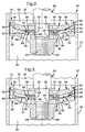
- Figure 2 is a fragmentary cross sectional view of the piston area of the damper of Figure 1 shown in a compression stroke.
- Figure 3 is a fragmentary cross sectional view of the suspension damper of Figure 1 shown in an extension stroke.
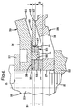
- Figure 4 is a detailed illustration of the monodisc valve area of the damper of Figure 1.
- Damper 10 is embodied as a monotube-type damper and includes a cylinder tube 12.
- a piston assembly 14 is slidably and sealingly carried in cylinder tube 12 dividing the interior thereof into a compression chamber 16 and an extension chamber 18.
- the piston assembly 14 is securely connected to turned down segment 21 of piston rod 20 and is maintained thereon by nut 22 which is secured on threaded segment 23.
- the piston rod 20 extends through the extension chamber 18 and exits the cylinder tube 12 for attachment to the body of a vehicle (not illustrated).
- the cylinder tube 12 is conventionally adapted for connection to the wheel assembly (not illustrated) which is associated with the vehicle and therefore, in response to relative movement between the wheel assembly and the vehicle the piston assembly 14 reciprocates within the cylinder tube 12.
- a combination bearing and seal element 24 of a low friction material is carried by the piston assembly 14 and provides a mating engagement with the cylinder tube 12.
- the piston assembly 14 includes a piston body 26 with a cylindrical skirt 28. A series of passageways, representative of which is passageway 30, are distributed about the piston body 26 and extend therethrough.
- the piston body 26 forms a cavity 32 which is radially bounded by the skirt 28 and which is open to the extension chamber 18.
- the piston valve assembly 34 is carried within the cavity 32 and is secured between annular shoulder 25 of piston rod 20 and the piston body 26.
- the valve assembly 34 includes a retainer 39 which is pressed onto turned down segment 21 in combination with a washer spacer 37 which positions the retainer 39 an appropriate distance away from the piston body 26.
- a bearing washer 38 and center washer 35 are carried on legs of retainer 39 representative of which is leg 45.
- a guide washer 33 fits onto the turned down segment 21 against center washer 35 and held by legs 45.
- An annular spacer 36 is pressed onto turned down segment 21 against guide washer 33 securing valve assembly 34 between the annular shoulder 25 and the piston body 26.
- An annular spring steel valve element designated as monodisc 40 is carried between bearing washer 38 and annular bearing 42, which is an integral part of piston body 26. Due to the spring-like nature of the monodisc 40 its inner perimeter 47 is biased against the bearing washer 38 and its outer perimeter 48 is biased against the annular bearing 42.
- the guide washer 33 is illustrated in greater detail in Figure 1B.
- the opening 53 permits the guide washer 33 to be loosely received over turned down segment 21 of rod 20.
- the opening 55 receives the leg 45 of retainer 39.
- the four radially extending projections 56-59 guide the monodisc 40 when it deflects during an extension stroke of the damper 10 to maintain a centered orientation within the piston assembly 14.
- the four spaces 61-64, around the outside of guide washer 33 provide a continuously open area for fluid flow around the inside diameter of the monodisc 40.
- the monodisc 40 is deflectable to the maximum travel position shown wherein the monodisc 40 is positioned in a substantially flat orientation against compression stop surface 51 of retainer 39.
- the compression stop surface 51 is oriented such that the monodisc 40 uniformly mates therewith with the inner perimeter 47 supported in a spaced away position from retainer 39 on annular bearing 42.
- the outer perimeter 48 travels through an arc between the annular bearing 42 and the compression stop surface 51. Unevenly supported deflection of the monodisc 40 would cause the length thereof between the inner perimeter 47 and the outer perimeter 48 to bend in response to the fluid pressure applied thereto. To remain below maximum stress levels in the monodisc 40 the deflection distance between the annular bearing 42 and the compression stop surface 51 is limited in conventional damper assemblies.
- Providing the uniformly flat compression stop surface 51 of the present invention permits increasing the deflection distance permissible between annular bearing 42 and compression stop surface 51 without surpassing the maximum stress level of monodisc 40. This is due to the fact that during the deflection travel of the monodisc 40 it is simply supported at its inner perimeter 47 and therefore, deflects linearly. The linear deflection is maintained by the uniform support provided by compression stop surface 51 which is designed to mate with the monodisc 40 without imparting a curved deflection to the monodisc 40.
- the damper 10 is shown with the piston assembly 14 moving in an extension direction within the cylinder tube 12.
- An increase in pressure in the extension chamber 18 causes the inner perimeter 47 of the monodisc 40 to deflect downward opening a flow path through the piston assembly 14.
- the area of the monodisc 40 adjacent the perimeter 48 is supported by the interior edge of the annular bearing 42 and, at the maximum extent of travel of the monodisc 40, it is uniformly supported on the extension stop surface 52 of the piston body 26.
- the monodisc 40 is simply supported near its outer perimeter 48 and thus deflects linearly. This linear orientation is maintained as it mates with compression stop surface 51.
- the shape of the stop surface 51 maintains the monodisc 40 in its naturally deflected state and avoids the imparting of stresses to the monodisc 40, beyond the maximum level of the material strength.
- a means of increasing the preload imparted to the monodisc 40 is provided up to 2.5 times greater than the amount of preload that can be imparted to a conventionally designed monodisc valve assembly.
- the total compression deflection that is made possible by the present invention without exceeding the maximum stress levels of the monodisc 40 are more than twice the maximum allowable with conventionally designed monodisc assemblies.
- the level of preload is determined by the equation (D+A)-(C+B) .
- D represents the amount of offset between the annular bearing 42 and the top of the piston body 26 at its inner perimeter 27
- A represents the thickness of the monodisc 40
- C represents the thickness of the guide washer 33 and annular spacer 36
- B represents the thickness of the center washer 35. Therefore, the inner perimeter 47 of the monodisc 40 is deflected downward a distance, defined by the above equation, below the outer perimeter 48 of the monodisc 40.
Landscapes
- Engineering & Computer Science (AREA)
- General Engineering & Computer Science (AREA)
- Mechanical Engineering (AREA)
- Fluid-Damping Devices (AREA)
Applications Claiming Priority (2)
| Application Number | Priority Date | Filing Date | Title |
|---|---|---|---|
| US08/603,519 US5709290A (en) | 1996-02-20 | 1996-02-20 | Monotube damper valve |
| US603519 | 1996-02-20 |
Publications (3)
| Publication Number | Publication Date |
|---|---|
| EP0791764A2 true EP0791764A2 (fr) | 1997-08-27 |
| EP0791764A3 EP0791764A3 (fr) | 1999-07-21 |
| EP0791764B1 EP0791764B1 (fr) | 2003-08-27 |
Family
ID=24415784
Family Applications (1)
| Application Number | Title | Priority Date | Filing Date |
|---|---|---|---|
| EP97200153A Expired - Lifetime EP0791764B1 (fr) | 1996-02-20 | 1997-01-20 | Soupape pour amortisseur monotube |
Country Status (3)
| Country | Link |
|---|---|
| US (1) | US5709290A (fr) |
| EP (1) | EP0791764B1 (fr) |
| DE (1) | DE69724307T2 (fr) |
Cited By (3)
| Publication number | Priority date | Publication date | Assignee | Title |
|---|---|---|---|---|
| EP1688339A1 (fr) * | 2005-02-08 | 2006-08-09 | Jtekt Corporation | Soupape d'amortissement et direction assistée hydraulique |
| EP1739322A3 (fr) * | 2005-07-02 | 2007-08-15 | Continental Aktiengesellschaft | Clapet amortisseur |
| WO2015055313A1 (fr) * | 2013-10-18 | 2015-04-23 | Thyssenkrupp Bilstein Gmbh | Amortisseur de vibrations à amortissement dépendant de l'amplitude |
Families Citing this family (12)
| Publication number | Priority date | Publication date | Assignee | Title |
|---|---|---|---|---|
| GB2356913B (en) * | 1999-11-30 | 2003-02-19 | Delphi Tech Inc | Shock absorber |
| US6644445B2 (en) * | 2001-11-19 | 2003-11-11 | Tenneco Automotive Operating Company Inc. | Floating port blocker |
| US7784392B1 (en) * | 2006-10-12 | 2010-08-31 | HDM Hydraulics, LLC | Hydraulic locking cylinder |
| SE531694C2 (sv) * | 2007-12-19 | 2009-07-07 | Oehlins Racing Ab | Stötdämpare med dubbelkolv |
| US8235186B2 (en) * | 2009-10-07 | 2012-08-07 | Multimatic Inc. | Hydraulic damper spool valve |
| JP5418778B2 (ja) * | 2010-02-26 | 2014-02-19 | 日立オートモティブシステムズ株式会社 | 緩衝器 |
| US8800732B2 (en) | 2011-02-25 | 2014-08-12 | Multimatic Inc. | Hydraulic damper spool valve |
| DE102014201481B4 (de) * | 2014-01-28 | 2022-03-10 | Zf Friedrichshafen Ag | Schwingungsdämpfer, sowie Kolbenventil für einen Schwingungsdämpfer |
| US9682605B2 (en) * | 2015-02-25 | 2017-06-20 | Michael A Ankney | Variable dampening speed piston head assembly for radio controlled cars shock absorber and method |
| JP7002395B2 (ja) * | 2018-04-06 | 2022-01-20 | Kyb株式会社 | バルブ及び緩衝器 |
| CN112922999A (zh) * | 2019-12-06 | 2021-06-08 | 观致汽车有限公司 | 活塞阀系及安装有该活塞阀系的减振器和车辆 |
| MX2022010982A (es) | 2020-03-04 | 2022-10-07 | Multimatic Inc | Valvula de carrete de amortiguador hidraulico avanzada. |
Family Cites Families (26)
| Publication number | Priority date | Publication date | Assignee | Title |
|---|---|---|---|---|
| DE4110023A1 (de) * | 1991-03-27 | 1992-10-01 | Ringsdorff Werke Gmbh | Stossdaempferkolben aus ungleichen, gefuegten teilen |
| BE631369A (fr) * | 1962-04-26 | 1900-01-01 | ||
| DE1655225A1 (de) * | 1967-02-23 | 1971-08-05 | Brueninghaus Gmbh Stahlwerke | Arbeitskolben mit Ventilanordnung |
| FR1553977A (fr) * | 1967-12-08 | 1969-01-17 | ||
| FR1578810A (fr) * | 1968-03-11 | 1969-08-22 | ||
| US3621951A (en) * | 1968-12-30 | 1971-11-23 | Leopold Franz Schmid | Throttle valve |
| FR2063666A5 (fr) * | 1969-10-27 | 1971-07-09 | Bourcier Carbon Christian | |
| US3827539A (en) * | 1970-06-12 | 1974-08-06 | Monroe Belgium Nv | Shock absorber and piston valve structure |
| US3845782A (en) * | 1970-12-14 | 1974-11-05 | Girling Ltd | Flow control valve for hydraulic damper and the like |
| US3844389A (en) * | 1972-07-17 | 1974-10-29 | C Bourcier | Pistons for hydraulic shock absorbers |
| US3831626A (en) * | 1972-12-14 | 1974-08-27 | Peddinghaus Carl Ullrich Dr | Piston for a shock absorber |
| US3957140A (en) * | 1975-02-11 | 1976-05-18 | Carl Ullrich Peddinghaus | Shock-absorber piston |
| US4045009A (en) * | 1975-11-17 | 1977-08-30 | General Motors Corporation | Energy absorbing unit with improved control valve |
| JPS55149438A (en) * | 1979-05-04 | 1980-11-20 | Yamaha Motor Co Ltd | Hydraulic buffer |
| JPS58121368A (ja) * | 1982-01-14 | 1983-07-19 | Hitachi Ltd | 往復動圧縮機用弁装置 |
| US4724937A (en) * | 1984-09-04 | 1988-02-16 | General Motors Corporation | Hydraulic damper for vehicles with variable deflected disk piston valving |
| US4934667A (en) * | 1986-08-13 | 1990-06-19 | General Motors Corporation | Air spring damper for vehicle suspension |
| FR2611844B1 (fr) * | 1987-03-06 | 1989-07-13 | Bourcier Carbon Christian | Assemblage de piston pour amortisseur hydraulique |
| JP2694465B2 (ja) * | 1989-05-19 | 1997-12-24 | トキコ株式会社 | 油圧緩衝器 |
| DE4008324C1 (en) * | 1990-03-15 | 1991-06-27 | Boge Ag, 5208 Eitorf, De | Variable hydraulic damper assembly - has piston with hollow end carrying two valve seat rings |
| US5180186A (en) * | 1991-11-12 | 1993-01-19 | General Motors Corporation | Strut and method for steer-sensitive damping |
| ES2115429B1 (es) * | 1993-05-10 | 1999-02-16 | Fichtel & Sachs Ag | Valvula para un amortiguador de vibraciones telescopico hidraulico. |
| US5345970A (en) * | 1993-09-02 | 1994-09-13 | Carrier Corporation | Virtual valve stop |
| US5425398A (en) * | 1994-03-28 | 1995-06-20 | General Motors Corporation | Valve for automotive damper |
| CN1071002C (zh) * | 1994-11-15 | 2001-09-12 | 三电有限公司 | 流体移动装置的阀门排放机构 |
| FR2738317B1 (fr) * | 1995-08-31 | 1997-10-17 | Soframca | Piston a clapet flottant pour tube d'amortisseur hydraulique, notamment de type monotube |
-
1996
- 1996-02-20 US US08/603,519 patent/US5709290A/en not_active Expired - Lifetime
-
1997
- 1997-01-20 EP EP97200153A patent/EP0791764B1/fr not_active Expired - Lifetime
- 1997-01-20 DE DE69724307T patent/DE69724307T2/de not_active Expired - Lifetime
Non-Patent Citations (1)
| Title |
|---|
| None |
Cited By (4)
| Publication number | Priority date | Publication date | Assignee | Title |
|---|---|---|---|---|
| EP1688339A1 (fr) * | 2005-02-08 | 2006-08-09 | Jtekt Corporation | Soupape d'amortissement et direction assistée hydraulique |
| US7574860B2 (en) | 2005-02-08 | 2009-08-18 | Jtekt Corporation | Damper valve and hydraulic power steering apparatus |
| EP1739322A3 (fr) * | 2005-07-02 | 2007-08-15 | Continental Aktiengesellschaft | Clapet amortisseur |
| WO2015055313A1 (fr) * | 2013-10-18 | 2015-04-23 | Thyssenkrupp Bilstein Gmbh | Amortisseur de vibrations à amortissement dépendant de l'amplitude |
Also Published As
| Publication number | Publication date |
|---|---|
| DE69724307T2 (de) | 2004-03-25 |
| DE69724307D1 (de) | 2003-10-02 |
| EP0791764A3 (fr) | 1999-07-21 |
| US5709290A (en) | 1998-01-20 |
| EP0791764B1 (fr) | 2003-08-27 |
Similar Documents
| Publication | Publication Date | Title |
|---|---|---|
| EP0791764B1 (fr) | Soupape pour amortisseur monotube | |
| US11131362B2 (en) | Hydraulic damper with a hydraulic compression stop assembly | |
| US6655512B2 (en) | Variable area low speed orifice in a vehicle damper | |
| US5738190A (en) | Flexing disc-blow off assembly for use in a shock absorber | |
| KR100221563B1 (ko) | 포핏밸브 | |
| CN110206844B (zh) | 阻尼器组件 | |
| US5921360A (en) | Digressive damper valve | |
| US7228948B2 (en) | Hydraulic suspension damper | |
| EP0458467A2 (fr) | Tampon d'arrêt hydraulique pour amortisseur de chocs | |
| US4819773A (en) | Valve structure for hydraulic damper | |
| US4185721A (en) | Springless seal for shock absorber | |
| JPH10132012A (ja) | 油圧ダンパ用フロート弁付きピストン | |
| JPH09506414A (ja) | 多数のエラストマー的シールを有するアキュムレータ・ピストン | |
| US4411342A (en) | Hydraulic damper | |
| US20050016805A1 (en) | Vibration damper for vehicles | |
| US4823922A (en) | Heavy duty vehicular shock absorber | |
| US4274517A (en) | Hydraulic shock absorber | |
| US4653618A (en) | Twin tube shock absorber gas seal | |
| US4245825A (en) | Shock absorber for wheeled vehicle | |
| US11396869B2 (en) | Seat valve | |
| KR960006362B1 (ko) | 선형 구동장치 | |
| US20020063023A1 (en) | Digressive piston compression valve | |
| US7201391B2 (en) | Front fork in two-wheeled vehicle or the like | |
| CN220668541U (zh) | 气动执行机构 | |
| CA1290357C (fr) | Soupape a ouverture rapide limitant les pointes de pression pour suspension hydropneumatique de vehicule lourd |
Legal Events
| Date | Code | Title | Description |
|---|---|---|---|
| PUAI | Public reference made under article 153(3) epc to a published international application that has entered the european phase |
Free format text: ORIGINAL CODE: 0009012 |
|
| AK | Designated contracting states |
Kind code of ref document: A2 Designated state(s): DE ES FR GB |
|
| PUAL | Search report despatched |
Free format text: ORIGINAL CODE: 0009013 |
|
| AK | Designated contracting states |
Kind code of ref document: A3 Designated state(s): DE ES FR GB |
|
| 17P | Request for examination filed |
Effective date: 20000121 |
|
| RAP1 | Party data changed (applicant data changed or rights of an application transferred) |
Owner name: DELPHI TECHNOLOGIES, INC. |
|
| 17Q | First examination report despatched |
Effective date: 20020325 |
|
| GRAH | Despatch of communication of intention to grant a patent |
Free format text: ORIGINAL CODE: EPIDOS IGRA |
|
| GRAH | Despatch of communication of intention to grant a patent |
Free format text: ORIGINAL CODE: EPIDOS IGRA |
|
| GRAA | (expected) grant |
Free format text: ORIGINAL CODE: 0009210 |
|
| AK | Designated contracting states |
Designated state(s): DE ES FR GB |
|
| PG25 | Lapsed in a contracting state [announced via postgrant information from national office to epo] |
Ref country code: FR Free format text: LAPSE BECAUSE OF FAILURE TO SUBMIT A TRANSLATION OF THE DESCRIPTION OR TO PAY THE FEE WITHIN THE PRESCRIBED TIME-LIMIT Effective date: 20030827 |
|
| REG | Reference to a national code |
Ref country code: GB Ref legal event code: FG4D |
|
| REF | Corresponds to: |
Ref document number: 69724307 Country of ref document: DE Date of ref document: 20031002 Kind code of ref document: P |
|
| PG25 | Lapsed in a contracting state [announced via postgrant information from national office to epo] |
Ref country code: ES Free format text: LAPSE BECAUSE OF FAILURE TO SUBMIT A TRANSLATION OF THE DESCRIPTION OR TO PAY THE FEE WITHIN THE PRESCRIBED TIME-LIMIT Effective date: 20031208 |
|
| PG25 | Lapsed in a contracting state [announced via postgrant information from national office to epo] |
Ref country code: GB Free format text: LAPSE BECAUSE OF NON-PAYMENT OF DUE FEES Effective date: 20040120 |
|
| PLBE | No opposition filed within time limit |
Free format text: ORIGINAL CODE: 0009261 |
|
| STAA | Information on the status of an ep patent application or granted ep patent |
Free format text: STATUS: NO OPPOSITION FILED WITHIN TIME LIMIT |
|
| 26N | No opposition filed |
Effective date: 20040528 |
|
| GBPC | Gb: european patent ceased through non-payment of renewal fee |
Effective date: 20040120 |
|
| EN | Fr: translation not filed | ||
| PGFP | Annual fee paid to national office [announced via postgrant information from national office to epo] |
Ref country code: DE Payment date: 20100114 Year of fee payment: 14 |
|
| REG | Reference to a national code |
Ref country code: DE Ref legal event code: R119 Ref document number: 69724307 Country of ref document: DE Effective date: 20110802 |
|
| PG25 | Lapsed in a contracting state [announced via postgrant information from national office to epo] |
Ref country code: DE Free format text: LAPSE BECAUSE OF NON-PAYMENT OF DUE FEES Effective date: 20110802 |