EP0791801A2 - Micromètre - Google Patents
Micromètre Download PDFInfo
- Publication number
- EP0791801A2 EP0791801A2 EP97301196A EP97301196A EP0791801A2 EP 0791801 A2 EP0791801 A2 EP 0791801A2 EP 97301196 A EP97301196 A EP 97301196A EP 97301196 A EP97301196 A EP 97301196A EP 0791801 A2 EP0791801 A2 EP 0791801A2
- Authority
- EP
- European Patent Office
- Prior art keywords
- spindle
- thimble
- axial direction
- end portion
- rotation
- Prior art date
- Legal status (The legal status is an assumption and is not a legal conclusion. Google has not performed a legal analysis and makes no representation as to the accuracy of the status listed.)
- Granted
Links
Images


Classifications
-
- G—PHYSICS
- G01—MEASURING; TESTING
- G01B—MEASURING LENGTH, THICKNESS OR SIMILAR LINEAR DIMENSIONS; MEASURING ANGLES; MEASURING AREAS; MEASURING IRREGULARITIES OF SURFACES OR CONTOURS
- G01B3/00—Measuring instruments characterised by the use of mechanical techniques
- G01B3/18—Micrometers
Definitions
- This invention relates to a micrometer of a digital readout type. More particularly, a micrometer, which a spindle is displaced in the axial direction during the rotation, is intended to be reduced cost and improved the operability.
- an electronic digital readout type measuring instrument is becoming pervasive to the overall measuring instrument in view of superiority over precision and ease of reading.
- a micrometer is also going to move to a digital readout integrated with a rotary encoder capable of reading a spindle which is displaced in the axial direction during the rotation as a thimble is rotated.
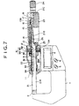
- an anvil 2 is fixed on an inner face of one end portion of a frame 1 as the main body formed in approximate U-shape, and further a spindle 21 is provided on the other end portion of the frame to move to and from the anvil 2 while being displaced in the axial direction.
- a numeral 4 means a digital readout indicating the degree of the displacement of the spindle 21 in directly readable numerals.
- a numeral 5 means a power ON/OFF switch.
- a numeral 6 means a zeroing switch returning a indicated numeral on the digital readout to zero.
- a bearing cylinder 11 is fixed on an inner side of the other end portion of the frame 1 which is provided with the spindle 21, and a retaining ring 12 is screwed onto an outer side of the other end portion.
- the central portion of the retaining ring 12 retains each end of an inner sleeve 13 and an outer sleeve 14 which are mounted on each other to form a double-cylinder structure at in and out.
- the inner sleeve 13 has a small-diameter tube portion 13A at one end portion thereof and the other end portion 13B which is formed in a cylindrical shape to be expanded in the radial direction by plural (normally, three) slits 15 formed along the axial direction.
- a female screw portion 16 is formed along the axial direction on the inner face of the other end portion 13B, and a male screw portion 18 is formed on the outer face of the other end portion 13B to be screwed onto a taper nut 17.
- the female screw portion 16 is screwed onto the spindle 21.
- the spindle 21 has a shaft portion 21A slidably supported by the bearing cylinder 11, a screw portion 21B having a slightly larger diameter than the shaft portion 21A and formed with male screw on the outer face thereof, and a taper portion 21C combinedly formed on one end portion of the screw portion 21B.
- the shaft portion 21A is formed with a sectionally V-shaped groove 22 along the axial direction of the outer circumference thereof.
- the screw portion 21B is screwed onto the female screw portion 16.
- the taper portion 21C is inserted into and secured with one end portion of a thimble 23 rotatably covered on the outer circumferential face of the outer sleeve 14.
- a ratchet knob 24 turning free when the spindle 21 receives more than a predetermined load is provided at the end of the thimble 23. Therefore, provided that the thimble 23 or the ratchet knob 24 is turned, the spindle 21 is displaced in the axial direction while being turned.
- the degree of the displacement of the spindle 21 can be read out on a main scale graduation 25, formed along the axial direction of the outer circumference of the outer sleeve 14 to be calibrated every regular intervals, and an auxiliary scale graduation 26 formed along the outer circumference of the thimble 23.
- a rotational cylinder 31 Between the end of the small-diameter tube portion 13A of the inner sleeve 13 and the bearing cylinder 11, a rotational cylinder 31, a first spacer 32 and a second spacer 33 are covered on the outer circumferential face of the spindle 21 in order to displace in the axial direction. And further, between the second spacer 33 and the bearing cylinder 11, a spring 34 is placed to forcibly move the second spacer 33, the first spacer 32 and the rotational cylinder 31 toward the right direction on Fig. 7.
- the rotational cylinder 31 is engaged with a screw 35 having a projection 35A slidably engaged in the groove 22. Thereby allowing the rotational cylinder 31 and the spindle 21 to be rotated in synchronism with each other and enabling the displacement of the spindle 21 in the axial direction.
- a capacitance encoder 41 is provided to detect the degree of displacement of the spindle 21 in the axial direction from the degree the spindle is rotated.
- the encoder 41 includes a fixed plate 43, adhesively attached on a plate 42 fixed to the retaining ring 12 and having a sending electrode and an output electrode (not shown), and a rotating plate 44, adhesively attached to the rotational cylinder 31 to face to the fixed plate 43 with a fixed space and having a receiving electrode and an associated electrode (not shown), in which the encoder 41 receives a signal responding to a relative rotational angle between the fixed plate 43 and the rotating plate 44 from the output electrode when a signal having different phase is given to the sending electrode.
- the signal responding to the relative rotational angle between the fixed plate 43 and the rotating plate 44 which is detected by the encoder 41, is indicated on the digital readout 4 in directly readable numerals after it is processed in a circuit (not shown).
- the aforementioned conventional digital readout type micrometer is structured to completely include the mechanical graduation display system in order to be used in the end of a life of power (battery) for driving the digital readout 4, the encoder 41, the circuit and so on. More specifically, the structure is to provide the outer sleeve 14 to the frame 1 and the thimble 23 to the spindle 21 and to form the main scale graduation 25 along the axial direction on the outer circumferential face of the outer sleeve 14 and the auxiliary scale graduation 26 along the circumference of the thimble 23. As a result, disadvantages of an intricate assembly and large cost are produced.
- a micrometer which has a main body having an anvil at one end portion thereof, a spindle displaced in the axial direction with the screwed rotation engaging the other end portion of the main body, an encoder detecting the degree of displacement of the spindle in the axial direction from the degree the spindle is rotated, and a digital readout indicating a measured value in directly readable numerals based on an output signal from the encoder, is characterized by including a thimble provided at a regular position in the axial direction of the spindle in the other end portion of the main body and to rotate about the axis of the spindle; and a rotation transfer means for transferring the rotation of the thimble to the spindle and allowing the displacement of the spindle in the axial direction, which is provided between the thimble and the spindle.
- a main scale graduation, an auxiliary scale graduation or the like included in a conventional micrometer is omitted, so that cost for providing the main scale graduation and so on can be reduced. Further, an outer sleeve in order to form the main scale graduation is not needed, so that the numbers of parts and processes can be decreased. Thus reducing cost.
- the rotation of the thimble is transferred through the rotation transfer means to the spindle.
- the spindle is screwed to the main body, so that the spindle is displaced in the axial direction with the rotation.
- the degree of displacement of the spindle is detected by the encoder, and then the digital readout indicates a measured value in directly readable numerals.
- the thimble is rotatably provided at the regular position in the frame, so that the thimble is not displaced with the spindle 61, thereby allowing a disadvantage of decreasing the operability, which is caused by the great displacement of the spindle 61, to be resolved.
- the rotation transfer means can be structured to be composed of a groove, formed along the axial direction on the outer circumferential face of the spindle, and a pin, slidably engaged in the groove to be projected to the inner face of the thimble, but, it is advisable to use, for example, a ratchet system transferring the rotation of the thimble to the spindle and causing the thimble to be rotated free relative to the spindle when the spindle receives more than predetermined load.
- the thimble when a measured subject is clamped between the spindle and the anvil, provided that more than predetermined load is acted to the spindle, the thimble is turned free relative to the spindle, so that the measurement can be carried out with a steady measuring pressure at all time. Therefore, the measurement can be insured with high-accuracy.
- the ratchet system is composed of a ratchet ring, secured in the thimble and having a saw-tooth projection on the inner circumferential face thereof, and a plate spring, inserted between the ratchet ring and the outer circumferetial face of the spindle, in which one end of the plate spring is engaged in the groove formed along the axial direction of the spindle, and the other end is forcibly pressed to the saw-tooth projection of the ratchet ring.
- the ratchet system is provided between the thimble and the spindle, so that the structure is simple. Further, the ratchet system is composed of two parts of the ratchet ring and the plate spring, so that the number of parts can be decreased and the assemble is easy, therefore it is possible to reduce cost.
- the thimble is composed of a cylinder body, supported in the other end portion of the main body to rotate about the axis of the spindle and accommodating the ratchet ring, and a cap screwed into the other end portion of the cylinder body and covering the other end portion of the spindle.
- the assembly when one end of the plate spring of the ratchet system is engaged in the groove formed along the axial direction of the spindle, the assembly can be carried out while looking through the hole of cylinder body, so that one end of the plate spring can be easily engaged in the groove of the spindle.
- the cap has a slightly larger internal diameter than the outer diameter of the spindle and doubles as a stopper to be abutted to the end face of the plate spring when being screwed into the other end portion of the cylinder body.
- the plate spring when the spindle is displaced in the axial direction, the plate spring is attempt to move in the axial direction with the spindle, but the cap interrupts this movement of the plate spring, therefore the plate spring can be retained at the original position.
- a collar portion is provided at an end of the cylinder body, and may be rotatably retained to be covered from the outside by a cap nut engaged to the main body.
- a barrierlayer type, a magnetic type or the like can be used, but it is desirable to use the capacitance encoder.
- a structure of the encoder to have a fixed plate, having a sending electrode and an output electrode secured in the main body, and a rotational plate, having a receiving electrode and an associated electrode and located onto the spindle through a rotational cylinder to face to the fixed plate with a fixed space, and to receive a signal responding to a relative rotational angle between the fixed plate and the rotational plate from the output electrode when a signal having different phase is given to the sending electrode, and that the rotational cylinder is screwed with a screw having a projection engaged to slide in the groove formed along the axial direction of the spindle, so that the rotational cylinder and the spindle are synchronistically rotated and the displacement of the spindle in the axial direction is allowed.
- the groove formed along the axial direction of the spindle can be doubled as the groove for engaging the plate spring composing the ratchet system, and the groove for rotating the rotational cylinder in synchronism with the spindle.
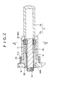
- the aforementioned outer sleeve 14 is omitted and a sleeve 51 shorter than the aforementioned inner sleeve 13 is retained in the aforementioned retaining ring 12.
- a nut member 52 formed with female screw on the inner face thereof, is secured to be pressed onto the inner face of the other end portion of the sleeve 51.
- the nut member 52 is screwed onto a spindle 61.
- the spindle 61 includes a shaft portion 61A, slidably supported in the aforementioned bearing cylinder 11, and a screw portion 61B having the same diameter as the shaft portion 61A and formed with screw, engaging with the nut member 52, on the outer circumeferential face thereof.
- a V-shaped groove 62, engaged with the aforementioned projection 35A of the screw 35, is formed along the axial direction the length of the screw portion 61B starting from some point on the shaft portion 61A.
- a tubular thimble 71 On the outer circumference of the sleeve 51, a tubular thimble 71, having a collar portion 71A at an end thereof, is provided to rotate about the axis of the spindle 61, and further, a cap nut 72, covering the collar portion 71A from the outside to retain the thimble 71 at a regular position in the axial direction, is screwed.
- the thimble 71 is composed of a cylinder body 73, supported on the outer circumference of the sleeve 51 to rotate about the axis of the spindle 61, and a cap 74 covering the other end portion of the spindle 61 to be screwed into the other end portion of the cylinder body 73.
- the internal diameter of the cap 74 is formed to be slightly larger than the outer diameter of the spindle 61. And, the cap 74 doubles as a stopper to be abutted to the end face of a plate spring 85 (mentioned below) when being screwed into the other end portion of the cylinder body 73.
- a rotation transfer means 81 for transferring the rotation of the thimble 71 to the spindle 61 and allowing the spindle to displace in the axial direction.
- a ratchet system 82 transferring the rotation of the thimble 71 to the spindle 61 and causing the thimble 71 to turn free relative to the spindle 61 when the spindle 61 receives more than a predetermined load, is used.
- the ratchet system 82 is composed of a ratchet ring 84, secured in the thimble 71 and having a saw-tooth projection 83 on the inner circumferential face thereof, and the plate spring 85, inserted between the ratchet ring 84 and the spindle 61 to be wound on the spindle 61, in which one end 85A of the plate spring 85 is engaged in the groove 62 formed along the axial direction of the spindle 61, and the other end 85B is forcibly pressed into the saw-tooth projection 83 of the ratchet ring 84.
- the assembly is carried out by the steps of removing the cap 74 from the cylinder body 73 of the thimble 71, and assembling the ratchet system 82 into the cylinder body 73. That is to say, after the ratchet ring 84 is secured to be pressed, the plate spring 85 is inserted along the inside of the secured ratchet ring 84.
- the cylinder body 73 assembled with the ratchet system 82 is covered on the outer circumference of the sleeve 51, and then the cap nut 72 is screwed from the outside to rotatably retain the cylinder body 73. At the time, the cylinder body 73 is rotatably retained with a circular adjustment to fit one end 85A of the plate spring 85 into the groove 62 of the spindle 61 while looking through the hole of the other end of the cylinder body 73. After that, the cap 74 is screwed into the cylinder body 73.
- the measurement for example, when the measured subject (not shown) is held with the left hand and the frame 1 is held with the right hand, provided that the thimble 71 is rotated with the thumb and the index finger of the right hand, the rotation of the thimble 71 is transferred through the ratchet system 82 to the spindle 61. Thereupon the spindle 61 is displaced in the axial direction with the rotation, because the spindle 61 is screwed into the nut member 52 provided to the frame 1. Thereby the digital readout 4 is indicated thereon a measured value in directly readable numerals after the degree of displacement of the spindle 61 is detected by the encoder 41.
- the spindle 61 cannot be displaced toward the anvil 2 any more, namely, cannot be rotated in the same direction, so that the ratchet ring 84 is turned free relative to the plate spring 85 of the ratchet system 82.
- a indicated value on the digital readout 4 is read, and then the measurement is carried out in the state of a steady measuring pressure.
- the main scale graduation or the auxiliary scale graduation included in the conventional micrometer is omitted, so that the outer sleeve for forming the main scale graduation is not needed naturally.
- cost of processing to form the main scale graduation and so on can be reduced and the numbers of parts and processes of the assembly can be also decreased, resulting in the reduction of cost.
- the thimble 71 is rotatably provided at a regular position in the axial direction of the spindle 61 through the sleeve 51 in the other end portion of the frame 1, and the rotation transfer means 81 is provided between the thimble 71 and spindle 61, so that, in the measurement, the rotation of the thimble 71 is transferred through the rotation transfer means 81 to the spindle 61 provided that the thimble 71 is rotated, thereby allowing the spindle 61 to be displaced in the axial direction.
- the digital readout 4 indicates a measured value in directly readable numerals.
- the thimble 71 is not displaced with the spindle 61, because the thimble 71 is rotatably provided at the regular position in the frame 1, thereby allowing a disadvantage of decreasing the operability, which is caused by the great displacement of the spindle 61, to be resolved.
- the rotation transfer means 81 is structured with the ratchet system 82, so that the thimble 71 is rotated free relative to the spindle 61 when the spindle 61 receives more than predetermined load in the state the measured subject is clamped between the spindle 61 and the anvil 2, thereby allowing the measurement to be carried out with the steady measuring pressure at all times. As a result, the high-precision measurement can be insured.
- the ratchet system 82 is composed of the ratchet ring 84, secured in the thimble 71 and having the saw-tooth projection 83 on the inner circumeferetial face thereof, and the plate spring 85 inserted between the ratchet ring 84 and the outer circumeferential face of the spindle 61, resulting in the simple structure with the smaller number of parts, ease of assembly and the reduction of cost. Furthermore, the plate spring 85 is forcibly pressed toward the outside, so that the screw portion 61B of the spindle 61 is not much damaged.
- the thimble 71 is composed of the cylinder body 73, rotatably supported in the the other end portion of the frame 1, and the cap 74 screwed into the other end portion of the cylinder body 73, so that the assembly, which the one end 85A of the plate spring 85 in the ratchet system 82 is engaged in the groove 62 of the spindle 61, is carried out while looking through the hole of cylinder body 73, with the result that one end 85A of the plate spring 85 is easily engaged in the groove 62 of the spindle 61.
- the groove 62A is doubled as a groove for displacing the spindle 61 in the axial direction while the rotational cylinder 31 is rotatcd in synchronism with the spindle 61, so that it is not needed that another groove is formed in order to engage the one end 85A of the plate spring 85.
- the internal diameter of the cap 74 is formed to be slightly larger than the outer diameter of the spindle 61, thereby the plate spring 85 is attempt to move in the axial direction with the spindle 61 when the spindle 61 is displaced in the axial direction, but the cap 74 interrupts the movement of the plate spring 85, therefore the plate spring 85 can be retained at the original position.
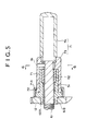
- the ratchet system 82 is used as the rotation transfer means 81, but another structure can be used insofar that the rotation of the thimble 71 is transferred to the spindle 61 and the spindle 61 is allowed to be displaced in the axial direction.
- the sectional rectangular groove 62A is formed along the axial direction of the spindle 61, and a pin 91 slidably engaged with the groove 62A can be projected to the inner face of the thimble 71.
- the rotation of the thimble 71 is transferred through the pin 91 and the groove 62 to the spind!e 61, and the displacement of the spindle 61 in the axial direction can be allowed at the groove 62A engaging the pin 91.
- a type of the encoder 41 is not limited to the rotary encoder composed of the fixed plate 43 and the rotational plate 44 as described in the aforementioned embodiment, and a cylindrical encoder having a coaxial cylindrical encoder (e.g., see Japanese Patent Application No. Hei 6-330689) can be used. And also, not only the capacitance encoder but also a barrier-layer type or a magnetic type encoder can be used.
- micrometer of the present invention cost can be reduced and the operability can be improved.
Landscapes
- Physics & Mathematics (AREA)
- General Physics & Mathematics (AREA)
- Length-Measuring Instruments Using Mechanical Means (AREA)
- Length Measuring Devices With Unspecified Measuring Means (AREA)
Applications Claiming Priority (3)
| Application Number | Priority Date | Filing Date | Title |
|---|---|---|---|
| JP37926/96 | 1996-02-26 | ||
| JP03792696A JP3623038B2 (ja) | 1996-02-26 | 1996-02-26 | マイクロメータ |
| JP3792696 | 1996-02-26 |
Publications (3)
| Publication Number | Publication Date |
|---|---|
| EP0791801A2 true EP0791801A2 (fr) | 1997-08-27 |
| EP0791801A3 EP0791801A3 (fr) | 1998-04-01 |
| EP0791801B1 EP0791801B1 (fr) | 2001-07-04 |
Family
ID=12511166
Family Applications (1)
| Application Number | Title | Priority Date | Filing Date |
|---|---|---|---|
| EP97301196A Expired - Lifetime EP0791801B1 (fr) | 1996-02-26 | 1997-02-24 | Micromètre |
Country Status (5)
| Country | Link |
|---|---|
| US (1) | US5829155A (fr) |
| EP (1) | EP0791801B1 (fr) |
| JP (1) | JP3623038B2 (fr) |
| CN (1) | CN1077281C (fr) |
| DE (1) | DE69705441T2 (fr) |
Cited By (6)
| Publication number | Priority date | Publication date | Assignee | Title |
|---|---|---|---|---|
| EP0831300A3 (fr) * | 1996-09-20 | 1998-04-15 | Mitutoyo Corporation | Capteur de déplacement du type capacitif |
| EP0973007A1 (fr) * | 1998-07-16 | 2000-01-19 | Brown & Sharpe Tesa S.A. | Dispositif de mesure longitudinale |
| EP1099928A1 (fr) * | 1999-11-10 | 2001-05-16 | Mitutoyo Corporation | Micromètre |
| US6243965B1 (en) | 1998-07-17 | 2001-06-12 | Brown & Sharpe Tesa Sa | Electronic micrometer |
| EP0947801A3 (fr) * | 1998-04-03 | 2001-09-05 | Mitutoyo Corporation | Micromètre |
| EP1564522A3 (fr) * | 2004-02-11 | 2014-11-05 | Carl Mahr Holding Gmbh | Micromètre |
Families Citing this family (15)
| Publication number | Priority date | Publication date | Assignee | Title |
|---|---|---|---|---|
| JPH11190601A (ja) * | 1997-12-26 | 1999-07-13 | Mitsutoyo Corp | マイクロメータ |
| JP3383229B2 (ja) * | 1998-11-11 | 2003-03-04 | 株式会社ミツトヨ | マイクロメータ |
| US6505414B2 (en) * | 2000-06-19 | 2003-01-14 | Mitutoyo Corporation | Comparator |
| JP3766801B2 (ja) * | 2001-12-28 | 2006-04-19 | 株式会社ミツトヨ | 測定器 |
| JP4516288B2 (ja) * | 2003-06-10 | 2010-08-04 | 株式会社ミツトヨ | デジタル式変位測定器 |
| JP4732050B2 (ja) * | 2005-07-22 | 2011-07-27 | 株式会社ミツトヨ | 測定器 |
| US7356941B2 (en) * | 2006-05-25 | 2008-04-15 | General Electric Company | Micrometer support apparatus and measurement method using same |
| JP4912765B2 (ja) * | 2006-06-26 | 2012-04-11 | 株式会社ミツトヨ | デジタル式変位測定器 |
| JP4825697B2 (ja) * | 2007-01-25 | 2011-11-30 | 株式会社ミツトヨ | デジタル式変位測定器 |
| TWI411763B (zh) * | 2007-11-23 | 2013-10-11 | Hon Hai Prec Ind Co Ltd | 分厘卡 |
| JP5270223B2 (ja) * | 2008-06-04 | 2013-08-21 | 株式会社ミツトヨ | マイクロメータ |
| JP5265982B2 (ja) * | 2008-07-29 | 2013-08-14 | 株式会社ミツトヨ | デジタル式変位測定器 |
| CN102294623A (zh) * | 2011-05-30 | 2011-12-28 | 刘红兵 | 数显自动测距尺和带有数显自动测距尺的切割机 |
| CN102927872B (zh) * | 2011-08-08 | 2017-03-08 | 孙生强 | 内径千分尺 |
| US9482509B2 (en) * | 2014-12-12 | 2016-11-01 | Mitutoyo Corporation | Ergonomic micrometer including two modes of adjustment |
Family Cites Families (14)
| Publication number | Priority date | Publication date | Assignee | Title |
|---|---|---|---|---|
| US319919A (en) * | 1885-06-09 | Micrometer-gage | ||
| US797745A (en) * | 1903-12-23 | 1905-08-22 | Charles W Pitman | Micrometer-gage. |
| GB1226037A (fr) * | 1968-10-02 | 1971-03-24 | ||
| CH510864A (de) * | 1969-06-18 | 1971-07-31 | Tsugami Taisuke | Digitalmikrometer |
| US3667127A (en) * | 1970-06-04 | 1972-06-06 | Taisuke Tsugami | Digital micrometer caliper |
| JPS6145441Y2 (fr) * | 1978-06-24 | 1986-12-20 | ||
| JPS57179701A (en) * | 1981-04-30 | 1982-11-05 | Mitsutoyo Mfg Co Ltd | Micrometer |
| DE3131673C2 (de) * | 1981-08-11 | 1984-01-19 | Dr. Johannes Heidenhain Gmbh, 8225 Traunreut | Digitales elektrisches Längenmeßgerät |
| US4553330A (en) * | 1982-12-20 | 1985-11-19 | Mitutoyo Mfg. Co., Ltd. | Micrometer |
| JPS59112202A (ja) * | 1982-12-20 | 1984-06-28 | Mitsutoyo Mfg Co Ltd | マイクロメ−タ |
| US4578868A (en) * | 1983-04-01 | 1986-04-01 | Mitutoyo Mfg. Co., Ltd. | Digital display measuring apparatus |
| DE3432405A1 (de) * | 1984-09-04 | 1986-03-13 | Mauser-Werke Oberndorf Gmbh, 7238 Oberndorf | Mikrometer |
| JPH06194102A (ja) * | 1992-12-24 | 1994-07-15 | Mitsutoyo Corp | マイクロメータ |
| JP2965444B2 (ja) * | 1993-10-01 | 1999-10-18 | 株式会社ミツトヨ | 定圧型測定機 |
-
1996
- 1996-02-26 JP JP03792696A patent/JP3623038B2/ja not_active Expired - Fee Related
-
1997
- 1997-02-24 US US08/805,155 patent/US5829155A/en not_active Expired - Lifetime
- 1997-02-24 EP EP97301196A patent/EP0791801B1/fr not_active Expired - Lifetime
- 1997-02-24 DE DE69705441T patent/DE69705441T2/de not_active Expired - Lifetime
- 1997-02-26 CN CN97109563A patent/CN1077281C/zh not_active Expired - Fee Related
Cited By (8)
| Publication number | Priority date | Publication date | Assignee | Title |
|---|---|---|---|---|
| EP0831300A3 (fr) * | 1996-09-20 | 1998-04-15 | Mitutoyo Corporation | Capteur de déplacement du type capacitif |
| US5920198A (en) * | 1996-09-20 | 1999-07-06 | Mitutoyo Corporation | Capacitance-type displacement measuring device |
| EP0947801A3 (fr) * | 1998-04-03 | 2001-09-05 | Mitutoyo Corporation | Micromètre |
| EP0973007A1 (fr) * | 1998-07-16 | 2000-01-19 | Brown & Sharpe Tesa S.A. | Dispositif de mesure longitudinale |
| US6243965B1 (en) | 1998-07-17 | 2001-06-12 | Brown & Sharpe Tesa Sa | Electronic micrometer |
| EP1099928A1 (fr) * | 1999-11-10 | 2001-05-16 | Mitutoyo Corporation | Micromètre |
| US6463671B1 (en) | 1999-11-10 | 2002-10-15 | Mitutoyo Corporation | Micrometer |
| EP1564522A3 (fr) * | 2004-02-11 | 2014-11-05 | Carl Mahr Holding Gmbh | Micromètre |
Also Published As
| Publication number | Publication date |
|---|---|
| JP3623038B2 (ja) | 2005-02-23 |
| JPH09229660A (ja) | 1997-09-05 |
| EP0791801B1 (fr) | 2001-07-04 |
| EP0791801A3 (fr) | 1998-04-01 |
| DE69705441T2 (de) | 2002-05-02 |
| CN1166594A (zh) | 1997-12-03 |
| US5829155A (en) | 1998-11-03 |
| DE69705441D1 (de) | 2001-08-09 |
| CN1077281C (zh) | 2002-01-02 |
Similar Documents
| Publication | Publication Date | Title |
|---|---|---|
| EP0791801B1 (fr) | Micromètre | |
| EP0947801B1 (fr) | Micromètre | |
| EP0831300B1 (fr) | Capteur de déplacement de type capacitif | |
| US5495677A (en) | Digital display micrometer gauge | |
| JP2761357B2 (ja) | 長さ測定器具の可動スピンドルによって加えられる締付け力を測定する工具 | |
| US4536963A (en) | Digital indication type measuring machine | |
| US7111413B2 (en) | Precision distance-measuring instrument | |
| JP3735546B2 (ja) | 内側マイクロメータ | |
| CN112352135A (zh) | 数字千分尺 | |
| GB2114749A (en) | Dial gauge | |
| JP3725151B2 (ja) | マイクロメータ | |
| JPH0374321B2 (fr) | ||
| CN112066933A (zh) | 三点接触式内齿跨距测量装置及测量方法 | |
| JP5426486B2 (ja) | 変位測定器 | |
| US6009749A (en) | Tire pressure gage | |
| JPS61111409A (ja) | エンコ−ダ内蔵型測定器 | |
| JP2596314Y2 (ja) | 変位検出装置 | |
| US4553330A (en) | Micrometer | |
| GB2028508A (en) | Digital electronic micrometer | |
| JPS6133521Y2 (fr) | ||
| JPH0434681B2 (fr) | ||
| CN213179802U (zh) | 三点接触式内齿跨距测量装置 | |
| JP2983810B2 (ja) | 定圧型測定機 | |
| JPH0421053Y2 (fr) | ||
| JPS5918321Y2 (ja) | カウント装置付マイクロメ−タ |
Legal Events
| Date | Code | Title | Description |
|---|---|---|---|
| PUAI | Public reference made under article 153(3) epc to a published international application that has entered the european phase |
Free format text: ORIGINAL CODE: 0009012 |
|
| AK | Designated contracting states |
Kind code of ref document: A2 Designated state(s): DE FR GB IT |
|
| PUAL | Search report despatched |
Free format text: ORIGINAL CODE: 0009013 |
|
| AK | Designated contracting states |
Kind code of ref document: A3 Designated state(s): DE FR GB IT |
|
| 17P | Request for examination filed |
Effective date: 19980929 |
|
| 17Q | First examination report despatched |
Effective date: 19990914 |
|
| GRAG | Despatch of communication of intention to grant |
Free format text: ORIGINAL CODE: EPIDOS AGRA |
|
| GRAG | Despatch of communication of intention to grant |
Free format text: ORIGINAL CODE: EPIDOS AGRA |
|
| GRAH | Despatch of communication of intention to grant a patent |
Free format text: ORIGINAL CODE: EPIDOS IGRA |
|
| GRAH | Despatch of communication of intention to grant a patent |
Free format text: ORIGINAL CODE: EPIDOS IGRA |
|
| GRAA | (expected) grant |
Free format text: ORIGINAL CODE: 0009210 |
|
| AK | Designated contracting states |
Kind code of ref document: B1 Designated state(s): DE FR GB IT |
|
| REF | Corresponds to: |
Ref document number: 69705441 Country of ref document: DE Date of ref document: 20010809 |
|
| ITF | It: translation for a ep patent filed | ||
| ET | Fr: translation filed | ||
| REG | Reference to a national code |
Ref country code: GB Ref legal event code: IF02 |
|
| PLBE | No opposition filed within time limit |
Free format text: ORIGINAL CODE: 0009261 |
|
| STAA | Information on the status of an ep patent application or granted ep patent |
Free format text: STATUS: NO OPPOSITION FILED WITHIN TIME LIMIT |
|
| 26N | No opposition filed | ||
| PGFP | Annual fee paid to national office [announced via postgrant information from national office to epo] |
Ref country code: DE Payment date: 20110216 Year of fee payment: 15 Ref country code: IT Payment date: 20110216 Year of fee payment: 15 Ref country code: FR Payment date: 20110218 Year of fee payment: 15 |
|
| PGFP | Annual fee paid to national office [announced via postgrant information from national office to epo] |
Ref country code: GB Payment date: 20110223 Year of fee payment: 15 |
|
| GBPC | Gb: european patent ceased through non-payment of renewal fee |
Effective date: 20120224 |
|
| REG | Reference to a national code |
Ref country code: FR Ref legal event code: ST Effective date: 20121031 |
|
| PG25 | Lapsed in a contracting state [announced via postgrant information from national office to epo] |
Ref country code: IT Free format text: LAPSE BECAUSE OF NON-PAYMENT OF DUE FEES Effective date: 20120224 |
|
| REG | Reference to a national code |
Ref country code: DE Ref legal event code: R119 Ref document number: 69705441 Country of ref document: DE Effective date: 20120901 |
|
| PG25 | Lapsed in a contracting state [announced via postgrant information from national office to epo] |
Ref country code: FR Free format text: LAPSE BECAUSE OF NON-PAYMENT OF DUE FEES Effective date: 20120229 Ref country code: GB Free format text: LAPSE BECAUSE OF NON-PAYMENT OF DUE FEES Effective date: 20120224 |
|
| PG25 | Lapsed in a contracting state [announced via postgrant information from national office to epo] |
Ref country code: DE Free format text: LAPSE BECAUSE OF NON-PAYMENT OF DUE FEES Effective date: 20120901 |