EP0791894A2 - Système et méthode d'affichage de plans de coupes obliques dans la région intérieure d'un objet solide - Google Patents
Système et méthode d'affichage de plans de coupes obliques dans la région intérieure d'un objet solide Download PDFInfo
- Publication number
- EP0791894A2 EP0791894A2 EP97108438A EP97108438A EP0791894A2 EP 0791894 A2 EP0791894 A2 EP 0791894A2 EP 97108438 A EP97108438 A EP 97108438A EP 97108438 A EP97108438 A EP 97108438A EP 0791894 A2 EP0791894 A2 EP 0791894A2
- Authority
- EP
- European Patent Office
- Prior art keywords
- values
- pixel
- cross
- plane
- cut plane
- Prior art date
- Legal status (The legal status is an assumption and is not a legal conclusion. Google has not performed a legal analysis and makes no representation as to the accuracy of the status listed.)
- Granted
Links
Images


Classifications
-
- G—PHYSICS
- G06—COMPUTING OR CALCULATING; COUNTING
- G06T—IMAGE DATA PROCESSING OR GENERATION, IN GENERAL
- G06T19/00—Manipulating three-dimensional [3D] models or images for computer graphics
-
- G—PHYSICS
- G06—COMPUTING OR CALCULATING; COUNTING
- G06T—IMAGE DATA PROCESSING OR GENERATION, IN GENERAL
- G06T15/00—Three-dimensional [3D] image rendering
- G06T15/08—Volume rendering
-
- G—PHYSICS
- G06—COMPUTING OR CALCULATING; COUNTING
- G06T—IMAGE DATA PROCESSING OR GENERATION, IN GENERAL
- G06T2219/00—Indexing scheme for manipulating 3D models or images for computer graphics
- G06T2219/008—Cut plane or projection plane definition
Definitions
- This invention relates to display systems and, more particularly, to the display of arbitrarily chosen cross sections of solid bodies for which values of physical properties are available at regular grid positions within the interior of such bodies.
- Such data can be obtained by non-intrusive methods such as computed axial tomographic (CAT) x-ray scanning systems, by nuclear magnetic resonance (NMR) imaging systems, or by other non-intrusive mechanisms such as ultrasound, positron emission tomography (PET), emission computed tomography (ECT) and multimodality imaging (MMI).
- CAT computed axial tomographic
- NMR nuclear magnetic resonance
- MMI multimodality imaging
- Each of these techniques produces a planar, grid-like array of values for each of a succession of slices of the solid object, thus providing a three-dimensional array of such values.
- the solid object is a human body or a portion thereof, although the method is equally applicable to other natural or artificial bodies.
- the physical value In the case of CAT scanning, the physical value would be the coefficient of x-ray absorption. For NMR imaging, the physical value would be the spin-spin or the spin-lattice relaxation time. In any event, the measured physical values reflect the variations in composition, density or surface characteristics of the underlying physical structures.
- Such a three-dimensional data array typically consists of a plurality of sets of three-dimensional (x, y, z) coordinates distributed at regular positions in a cubic or parallelepiped lattice within the body, and at least one value (V xyz ) of the physical property being associated with each respective one of the coordinate positions. Each cubically adjacent set of eight such positions defines a cubic volume called a "voxel" with a physical property value being specified for each of the eight voxel vertices.
- this surface must be shaded so as to give the human eye the correct impression of the shape and disposition of that surface when it is displayed on a two-dimensional display device.
- the angular direction of a vector normal or orthogonal to the surface at each point on the surface is compared to the viewing angle of the observer.
- the intensity of shading can then be adjusted so as to be proportional to the difference between these angles.
- Such angular difference information can also be used to control the colors incorporated in the displayed images, thus providing yet another visual clue to the surface disposition. Normal vectors with components directed away from the viewing angle can be ignored since the associated surfaces are hidden from view.
- One method for approximating the surface of an internal structure is the so called "marching cubes" method, disclosed by H.E. Cline et al. US patent 4,710,876, granted December 1, 1987, and assigned to applicants' assignee.
- the surface segment intersecting a voxel is approximated by one of a limited number of standardized plane polygonal surfaces intersecting the voxel.
- One particular standardized surface is selected by a vector representing the binary differences between the threshold value and the eight voxel vertex values.
- the surface-to-voxel intersection coordinates, as well as the normal vector, for each such standardized polygonal surface set can then be calculated or obtained by table look-up techniques.
- the final surface is assembled as a mosaic, using all the standardized polygons as tessera or tiles. Appropriate intensity values derived from the normal vector angles can be displayed immediately for viewing, or stored for later display.
- H. E. Cline et al. Serial Number 907,333, filed September 15, 1986, (US-A-4791567) discloses another technique of segregating similar structures by determining connectivity from adjacency information.
- one aspect of the invention seeks to provide an interactive method and apparatus for displaying two-dimensional cross-sectional images of a three-dimensional body.
- Another aspect of the invention seeks to provide a system for displaying a three-dimensional array of physical values in a two-dimensional cross section taken in a selectable viewing plane.
- Another aspect of the invention seeks to provide a system for displaying, with controllable pixel density, two-dimensional cross-sectional images of a three-dimensional body.
- Another aspect of the invention seeks to provide a system for displaying in real time, with selectable enlargement capability, two-dimensional cross-sectional images of a three-dimensional body.
- cross sections at arbitrarily selected cut planes are displayed for three-dimensional regular arrays of physical values by 1) rotating and displacing a plane of pixel locations to coincide with the desired cross-sectional cut plane and 2) calculating, for each pixel on the cut plane, a value for the physical property at the pixel location by tri-linear interpolation, using the original values at the vertices of the voxel including the pixel.
- a pixel is defined as a single picture element on a two-dimensional array of picture elements making up the two-dimensional picture.
- a voxel as defined above, is a three-dimensional parallelepiped in the data space having data values specified for each of the eight vertices of the parallelepiped. Such voxels are formed from the original array of data by assembling four cubically adjacent values from each of two successive planar arrays (slices) of data.
- the resolution of the final cut plane image is arbitrarily controlled by selecting the pixel location density in the original rotated plane of pixels. A value is then interpolated for each pixel in the rotated plane. More specifically, for each pixel location (x, y, z) translated into the cut plane, the translated pixel location is specified by x ⁇ , y ⁇ , z ⁇ coordinates, each such coordinate being represented in integer and fractional units normalized to the voxel edge dimension. The integer parts of the x-y-z coordinates (l x ⁇ , l y ⁇ , l z ⁇ ) are used to select the particular voxel containing the pixel.
- the fractional parts of the coordinates (F x ⁇ -F y ⁇ -F z ⁇ ) are used to interpolate the pixel value from the eight vertex values of the selected voxel.
- the pixel position rotations and value interpolations can be done sufficiently fast to permit real time, interactive selection of the cutting plane as cross sections are being displayed.
- the pixels can be generated, one at a time, in a raster scan order on the cutting plane and immediately displayed as generated. In this way, the cross-sectional image is displayed as fast as it can be generated, further increasing the speed of response of the cross section generator.
- the pixel density can be selected to correspond to the resolution capacity of the display device, thus taking full advantage of the resolution capability of the display device.
- a portion only of the cut plane can be selected and enlarged for display, thus providing real time "zooming" capability in the cross section generator. More particularly, the coordinates of a "window" in the cut plane can be used to select only a portion of the cut plane pixel positions. Data values for only this subset of pixel positions need then be calculated for viewing. The pixel density in such a window can be increased to again maximize the resolution in the resulting smaller partial plane cross-sectional display. Using this zooming capability, the body can be "searched" by lower resolution, full body cross-sectional scans to locate the particular structures of immediate interest. The structures of interest thus located can then be displayed in greater detail by increasing the pixel resolution in a smaller window within the selected body cross section.
- a sequence of voxel elements is used to calculate the value of included pixels.
- Data from consecutive NMR or CAT scan slices are assembled into a three-dimensional array of values which can then be analyzed or processed to obtain two-dimensional images of the three-dimensional information.
- the derivation of such three-dimensional interior data arrays is well known in the art and will not be further described here.
- Such data arrays are readily obtainable by well-known, non-intrusive methods such as computed axial tomographic (CAT) x-ray scanning systems, by nuclear magnetic resonance (NMR) imaging systems, by ultrasound scanning, by positron emission tomography (PET), by emission computed tomography (ECT) and by multimodality imaging (MMI).
- CAT computed axial tomographic
- NMR nuclear magnetic resonance
- PET positron emission tomography
- ECT emission computed tomography
- MMI multimodality imaging
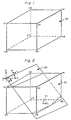
- FIG. 1 illustrates a single voxel element 52 with vertices V1 through V8.
- Each voxel element like element 52, spans two successive slices of data values.
- a data value which represents the measurement of at least one physical property which is associated with the corresponding spatial position within the three-dimensional body.
- the spatial positions are located in regular patterns defining regularly spaced grid locations within the body.
- the grid positions define a plurality of adjacent voxels like voxel 52 in FIG. 1.
- a plane of pixel locations is rotated and translated to coincide with the cut plane along which a cross-sectional view is to be displayed.
- An illustration of such a rotated and translated plane is shown in FIG. 2 for the same voxel as that shown in FIG. 1.
- FIG. 2 there is shown a portion 50 of a cut plane in the vicinity of voxel 52 of FIG. 1.
- the cut plane section 50 includes a single pixel location 51 within the interior of voxel 52.
- the density of the pixels is controllable and hence there might well be more than one pixel location within voxel 52, or there might be no pixel locations within voxel 52.
- the cut plane 50 makes an angle ⁇ with the x-axis and an angle ⁇ with the y-axis of the data coordinate system of which voxel 52 is a part. After angular rotation, the cut plane 50 is displaced in the vertical direction by a line segment length L z in the z direction (not shown in FIG. 2) from the origin of the coordinate system, usually taken as some location on the exterior of the data array coordinates.
- L z in the z direction not shown in FIG. 2
- the relationships necessary to rotate and translate three-dimensional coordinate positions are well known, and are disclosed in Fundamentals of Interactive Computer Graphics , by J.D. Foley and A. Van Dam, Addison-Wesley Publishing Co., Reading, Massachusetts, 1982, at pages 255-261.
- equation (7.42) at page 258 of the reference teaches a rotation and translation matrix of the following form: where x, y and z are the initial coordinates, M ij are the rotational coefficients, and t n are the translation coefficients.
- x, y and z are the initial coordinates
- M ij are the rotational coefficients
- t n are the translation coefficients.
- FIG. 3 shows a schematic, two-dimensional illustration of a plane of pixels rotated and displaced to lie along the desired arbitrary cut plane.
- a cut plane can be specified by an angular orientation and by a distance from the origin of the three-dimensional volume of the data voxels.
- the cut plane 10 (seen on edge for convenience) is uniquely identified by the length L z of line segment 13 and the angle 12 ( ⁇ ) line segment 13 makes with the x-axis of the coordinate system specifying the voxel locations.
- the selected cut plane 10 is that plane located at the end of vector 13 and making the angle ⁇ with the x-axis of the coordinate system of FIG. 3.
- the angular orientation of the cut plane is specified by two angles, the angle 12 with the x-z plane, corresponding to the angle ⁇ in FIG. 2, and a similar angle with the x-y plane, not visible in FIG. 3, but corresponding to the angle ⁇ in FIG. 2.
- the position and orientation of the cut plane 10 can therefore be uniquely specified by an angular orientation ( ⁇ and ⁇ ) and a vector length (L z ) from the origin of the data grid. In order to arbitrarily select cut planes, it is therefore necessary to provide a mechanism for specifying the angular orientation and the depth of the cut plane.
- the density of the pixel positions is controllable and corresponds to the desired resolution of the ultimately displayed image.
- the plane of pixel positions is then rotated and displaced in the z direction to coincide with the cut plane 10.
- each of dots 15 corresponds to one row of pixels in the cut plane 10.
- a pixel position x,y,z is rotated by rotation coefficients M ij and displaced in the z direction by the length L z to a point x ⁇ , y ⁇ , z ⁇ in the data space.
- the rotation operations of equations (2) are equivalent to the rotation matrix R of equation (1).
- the rotated plane is then translated in the z direction by a distance L z to coincide with cut plane 10 in FIG. 3 by subtracting the value L z from each of the z components.
- a plane of pixel positions which lies on the desired cut plane and which includes the pixel position density necessary to provide the desired resolution of the ultimate image.
- Each pixel position consists of the x ⁇ , y ⁇ , z ⁇ values given by equations (2), translated in the z direction by the value L z .
- each of these values is normalized to integer and fractional voxel edge units. That is, each of the transformed values has an integer part (i.e., before the decimal point) and a fractional part (i.e., after the decimal point), expressed in units equal to the length of one edge of a voxel.
- FIG. 4 there is shown a perspective view of one voxel of the three-dimensional data accumulated, for example, by CAT scan techniques.
- the voxel of FIG. 4 includes eight vertices V1 through V8.
- a data value is available for each of the grid positions corresponding to vertices V1-V8.
- a data value V for the pixel location 51 on the cut plane is interpolated in three dimensions by using the surrounding data values V1-V8 at the voxel vertices.
- the integer coordinate portions (l x ⁇ , l y ⁇ , l z ⁇ ) can be used to identify (and hence access) the corresponding voxel vertex values.
- the fractional coordinates (F x ⁇ , F y ⁇ , F z ⁇ ) can then be used to perform the three-dimensional interpolation necessary to obtain the data value at pixel position V. More specifically, using the nomenclature of FIG.
- edges V1-V2, V3-V4, V5-V6 and V7-V8 are divided in proportion to the fractional voxel coordinate F x ⁇ in the x direction to obtain points A1-A4.
- points B1 and B2 are located by interpolating between the line segments A1-A3 and A2-A4, using the data values at positions A1-A4 and the fractional voxel coordinate F y ⁇ in the y direction.
- the data value at the pixel position V is determined by interpolating between points B1 and B2, using the fractional voxel coordinate F z ⁇ in the z direction.
- the interpolation is linear, using the fractional coordinates (F x ⁇ , F y ⁇ , F z ⁇ ) obtained from the rotational operation of equations (2).
- FIG. 5 there is shown a cross-sectional image generation system comprising a three-dimensional memory storage system 20 for storing a three-dimensional array of values of at least one physical property at regular grid points in the interior of a physical body.
- the physical body may be a human body or any other body for which the internal structure is not readily seen, but for which internal physical data can be acquired by such non-intrusive means as CAT scanning or NMR imaging.
- the techniques for acquiring such three-dimensional data are well known and will not be further described here.
- a user-controlled cut plane orientation device 21 allows the user to specify the angular orientation of the cut plane along which the cross-sectional image is to be generated.
- This orientation can be specified by two angles, one from the x plane and the other from the y plane, as illustrated in FIG. 2.
- Such angular input can be specified by keyboard, rheostat, joy-stick, mouse, or any other analog input device.
- a track-ball having two degrees of angular freedom is used to specify cut plane orientation.
- Such track-balls are well known in the art and will not be further described here.
- the angular specification of the orientation of the cut plane is applied to a matrix storage device 22 which contains the rotational coefficients M 11 through M 33 of equations (2).
- matrix store 22 The function of matrix store 22 is to store all of the coefficients for each of the possible rotations, quantized to the granularity made possible with the orientation input device 21 and consonant with the resolution of the display device to be used. Orientation device 21 then operates to select the specific coefficients required for a particular set of orientation angles from an array of such coefficients. Alternatively, the necessary matrix coefficients can be calculated "on the fly", i.e., during ongoing operation, as needed, using the standard coordinate translating equations discussed in the before-mentioned Van Dam reference. These coefficients are supplied from matrix store 22 to a rotate operator circuit 23.
- a depth selection device 24 is used to select the depth (L z ) of the cut plane from the coordinate origin at the outer surface of the three-dimensional body. This depth indication is also supplied to rotate circuit 23 to provide a simple z-axis offset to the calculated cut plane position values.
- Depth generator 24 may comprise a keyboard, rheostat or other analog input device. A linear slide rheostat is the preferred depth input device to provide a sense of linear movement within the data space.
- a pixel generating device 25 is used to specify the pixel density on the cut plane.
- This pixel density generation is conveniently implemented by an x-axis counter and a y-axis counter.
- the x-axis counter is driven by clock pulses to sequentially generate x-axis pixel locations.
- the x-axis counter is reset at the pixel position corresponding to the end of each scanned horizontal line.
- the y-axis counter is advanced by one each time the x-axis counter is reset and thus provides the y-axis pixel locations.
- Pixel density is controlled by selecting only a subset of the generated x-axis and y-axis pixel locations (every count, every other count, every third count, etc.).
- the rotate circuit 23 of FIG. 5 implements the transformations specified by equations (2) and the linear translation in the z direction.
- Circuit 23 may comprise, for example, special purpose high speed integrated circuit chips to perform the multiplications, additions and subtractions in a parallel fashion.
- circuit 23 may be implemented by a programmed computer, either a high speed serial computer, or a parallel multiprocessor computer.
- the rotation operations specified by equations (2) are performed sufficiently rapidly to permit real time, interactive display of cross-sectional views as the user manipulates the orientation device 21 and the depth device 24.
- devices 21 and 24 may comprise any readily manipulated, continuously selective analog or digital input devices.
- the rotational transformation of x, y and z into x ⁇ , y ⁇ , and z ⁇ produces an integer portion and a fractional portion for each component.
- the integer portion of each component of the translated pixel position is fed to an address generator 26 which generates the address of the particular voxel within which the corresponding pixel is located. Since the voxels are cubical, and if the rotational arithmetic is carried out in units equal to a voxel edge length, then the integer portion of the resulting transformed coordinate is the address offset for that particular voxel in each coordinate direction.
- the address of the voxel in which the particular pixel is located is supplied to three-dimensional memory 20 to select the data values associated with the addressed voxel and place these data values in voxel register 27.
- interpolation circuit 29 uses the voxel data values in voxel register 27 and the fractional pixel component values in register 28 to implement the three-dimensional linear interpolation of equations (3).
- interpolation circuit 29 may comprise special purpose integrated circuit chips carrying out the arithmetic relationships of equations (3), or may comprise a high speed serial programmed digital computer or a parallel processor.
- interpolation circuit 29 supplies an interpolated data value for each of the pixel positions specified by pixel generator 25. These data values, along with the corresponding pixel positions from generator 25, are supplied to an image generator 30.
- the pixels can be immediately displayed by image generator 30. Indeed, if the pixel positions are supplied by pixel generator 25 in the same order as the pixel plane would be scanned by a raster scanner, then the cross-sectional image can be displayed as it is generated, without any intermediate storage. Since rapid display is one of the principal goals of the preferred embodiment of the invention, it provides such raster scanning sequence of pixel values.
- the pixel values can be stored as a matrix of intensity values to be displayed at a later time. Presumably, the desired cross-sectional image will be saved as a stored matrix in long term storage facilities for later reviewing.
- the pixel generator 25 supplies a sequence of pixel coordinates x, y and z to the rotate circuit 23.
- rotate circuit 23 (using orientation information from generator 21 and depth information from generator 24) generates the integer and fractional portions of the corresponding translated and rotated x ⁇ , y ⁇ and z ⁇ coordinates.
- the integer portion of these translated and rotated coordinates is supplied to address generator 26 while the fractional portion is supplied to register 28.
- the address provided by address generator 26 accesses three-dimensional memory 20 to retrieve the voxel data values corresponding to that voxel address.
- the retrieved data values are stored in voxel register 27 and used, together with the fractional voxel coordinates in register 28, to calculate the interpolated pixel value corresponding to the initially supplied pixel coordinates from pixel generator 25.
- the pixel coordinates from generator 25 and the pixel intensity values from interpolation circuit 29 are used by image generator circuit 30 to generate and display the corresponding pixel of the cross-sectional image.
- the cross section generator can be used interactively, in real time, to generate a plurality of cross-sectional images on device 30.
- the user can manipulate the orientation generator 21 and the depth generator 24 to search for the particular cross section desired.
- the pixel generator 25 can be manipulated, by gating the desired subset of pixel locations to rotate circuit 23, to control the resolution (pixels per square inch) of the resulting image. In this way, the resolution capacity of the image generation device 30 can be exactly matched by the pixel density of the cross-sectional image, thus optimizing the resolution of the overall system.
- the pixel location coordinates generated by pixel generator 25 in FIG. 5 can be selected to be within any desired range of x and y values. In this way, a window can be created in the cut plane to display only a portion of the cross section. By expanding the window to fill the entire screen of the display device, a "zoom" effect can be implemented. Moreover, the resolution within the enlarged window can be increased by increasing the pixel density in that window area, thus simultaneously providing a restricted viewing window and a concomitantly higher resolution image. Only the data values for the restricted area are generated since only these pixel locations are passed on to rotate circuit 23.
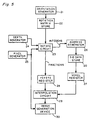
- FIG. 6 is a flowchart of the operations performed by the block diagram of FIG 5, with each box signifying a separate operation.
- box 60 of FIG. 6 the three-dimensional array of physical data values is obtained, either by searching a stored array of such values, or by generating values by non-intrusive body scanning techniques.
- box 61 the orientation and depth of the cut plane is selected in order to fully specify the cross section to be viewed.
- box 62 the pixel density is selected to control the resolution of the displayed image.
- the pixels thus specified are translated into the selected cut plane in box 63, using the translation formulae of equations (2).
- box 64 the pixel values are interpolated from the voxel vertex values of the voxel in which the translated pixel is located.
- box 65 the pixel locations and the pixel values are combined to form a cross-sectional image.
Landscapes
- Engineering & Computer Science (AREA)
- Computer Graphics (AREA)
- Physics & Mathematics (AREA)
- General Physics & Mathematics (AREA)
- Theoretical Computer Science (AREA)
- General Engineering & Computer Science (AREA)
- Computer Hardware Design (AREA)
- Software Systems (AREA)
- Apparatus For Radiation Diagnosis (AREA)
- Image Generation (AREA)
- Magnetic Resonance Imaging Apparatus (AREA)
- Image Processing (AREA)
- Image Analysis (AREA)
- Nuclear Medicine (AREA)
- Ultra Sonic Daignosis Equipment (AREA)
Applications Claiming Priority (3)
| Application Number | Priority Date | Filing Date | Title |
|---|---|---|---|
| US07/247,183 US4984157A (en) | 1988-09-21 | 1988-09-21 | System and method for displaying oblique planar cross sections of a solid body using tri-linear interpolation to determine pixel position dataes |
| EP89309414A EP0365141B1 (fr) | 1988-09-21 | 1989-09-15 | Système et méthode d'affichage de plans de coupes obliques dans la région intérieure d'un objet solide |
| US247183 | 2002-09-18 |
Related Parent Applications (2)
| Application Number | Title | Priority Date | Filing Date |
|---|---|---|---|
| EP89309414.4 Division | 1989-09-15 | ||
| EP89309414A Division EP0365141B1 (fr) | 1988-09-21 | 1989-09-15 | Système et méthode d'affichage de plans de coupes obliques dans la région intérieure d'un objet solide |
Publications (3)
| Publication Number | Publication Date |
|---|---|
| EP0791894A2 true EP0791894A2 (fr) | 1997-08-27 |
| EP0791894A3 EP0791894A3 (fr) | 1997-10-15 |
| EP0791894B1 EP0791894B1 (fr) | 2000-05-17 |
Family
ID=22933918
Family Applications (2)
| Application Number | Title | Priority Date | Filing Date |
|---|---|---|---|
| EP89309414A Expired - Lifetime EP0365141B1 (fr) | 1988-09-21 | 1989-09-15 | Système et méthode d'affichage de plans de coupes obliques dans la région intérieure d'un objet solide |
| EP97108438A Expired - Lifetime EP0791894B1 (fr) | 1988-09-21 | 1989-09-15 | Système et méthode d'affichage de plans de coupes obliques dans la région intérieure d'un objet solide |
Family Applications Before (1)
| Application Number | Title | Priority Date | Filing Date |
|---|---|---|---|
| EP89309414A Expired - Lifetime EP0365141B1 (fr) | 1988-09-21 | 1989-09-15 | Système et méthode d'affichage de plans de coupes obliques dans la région intérieure d'un objet solide |
Country Status (5)
| Country | Link |
|---|---|
| US (1) | US4984157A (fr) |
| EP (2) | EP0365141B1 (fr) |
| JP (1) | JP2885842B2 (fr) |
| DE (2) | DE68928979T2 (fr) |
| IL (1) | IL91435A (fr) |
Cited By (5)
| Publication number | Priority date | Publication date | Assignee | Title |
|---|---|---|---|---|
| EP1001379A3 (fr) * | 1998-11-12 | 2002-07-10 | TeraRecon, Inc., A Delaware Corporation | Région de plan de coupe calculée incrémentalement pour voir une portion d'un ensemble de données de volume en temps réel |
| WO2002043009A3 (fr) * | 2000-10-23 | 2002-08-29 | Siemens Corp Res Inc | Procede permettant d'accelerer la production et l'affichage de vues eclatees de rendus de volume d'images en trois dimensions |
| WO2002041256A3 (fr) * | 2000-11-20 | 2002-09-12 | Koninkl Philips Electronics Nv | Dispositif d'analyse medicale |
| WO2004008640A3 (fr) * | 2002-07-16 | 2004-08-19 | Koninkl Philips Electronics Nv | Unite de lecture de surface interne de reformatage plane |
| EP1914685A2 (fr) | 2006-10-16 | 2008-04-23 | Georg-Friedemann Dr. Rust | Représentation imagée de jeux de données tridimensionnels |
Families Citing this family (100)
| Publication number | Priority date | Publication date | Assignee | Title |
|---|---|---|---|---|
| JPH02173878A (ja) * | 1988-12-27 | 1990-07-05 | Toshiba Corp | 3次元断面表示装置 |
| US5113357A (en) * | 1989-05-18 | 1992-05-12 | Sun Microsystems, Inc. | Method and apparatus for rendering of geometric volumes |
| US5226113A (en) * | 1989-10-30 | 1993-07-06 | General Electric Company | Method and apparatus for volumetric projection rendering using reverse ray casting |
| FR2656129B1 (fr) * | 1989-12-20 | 1992-03-13 | Gen Electric Cgr | Procede de reconstruction multi-echelle de l'image de la structure d'un corps. |
| US5086401A (en) * | 1990-05-11 | 1992-02-04 | International Business Machines Corporation | Image-directed robotic system for precise robotic surgery including redundant consistency checking |
| US5359704A (en) * | 1991-10-30 | 1994-10-25 | International Business Machines Corporation | Method for selecting silhouette and visible edges in wire frame images in a computer graphics display system |
| US5355504A (en) * | 1991-11-19 | 1994-10-11 | Intel Corporation | Self-synchronizing data queues |
| US5734384A (en) * | 1991-11-29 | 1998-03-31 | Picker International, Inc. | Cross-referenced sectioning and reprojection of diagnostic image volumes |
| EP0549182A2 (fr) * | 1991-12-23 | 1993-06-30 | General Electric Company | Appareil et procédé pour l'affichage de coupes chirurgicales dans des modèles tri-dimensionnels |
| DE69233043T2 (de) * | 1991-12-23 | 2004-03-18 | General Electric Co. | Erzeugung von Festkörpermodellen mit dem Spannverfahren unter Anwendung von Würfelteilung |
| DE69233060T2 (de) * | 1991-12-23 | 2004-04-08 | General Electric Co. | System zur Anzeige von räumlichen Einschnitten für Festkörpermodellflächen |
| EP0549185A2 (fr) * | 1991-12-23 | 1993-06-30 | General Electric Company | Système pour la conversion à balayage tri-dimensionnel d'un modèle polygonal dans un format "point et normale", affiché avec l'utilisation d'un circuit accélérateur |
| US5428716A (en) * | 1991-12-26 | 1995-06-27 | International Business Machines Corporation | Solid-clip methodology and architecture for clipping solid models and displaying cross-sections using depth-buffers |
| US5274472A (en) * | 1992-05-21 | 1993-12-28 | Xerox Corporation | High addressability image generator using pseudo interpolation of video and screen data |
| US5646696A (en) * | 1992-12-23 | 1997-07-08 | Intel Corporation | Continuously changing image scaling performed by incremented pixel interpolation |
| US5497453A (en) * | 1993-01-05 | 1996-03-05 | International Business Machines Corporation | Method and apparatus for detecting and visualizing interferences between solids |
| US5898793A (en) * | 1993-04-13 | 1999-04-27 | Karron; Daniel | System and method for surface rendering of internal structures within the interior of a solid object |
| US5412563A (en) * | 1993-09-16 | 1995-05-02 | General Electric Company | Gradient image segmentation method |
| US5594842A (en) * | 1994-09-06 | 1997-01-14 | The Research Foundation Of State University Of New York | Apparatus and method for real-time volume visualization |
| WO1996007989A1 (fr) * | 1994-09-06 | 1996-03-14 | The Research Foundation Of State University Of New York | Appareil et procede de visualisation de volume en temps reel |
| US5570460A (en) * | 1994-10-21 | 1996-10-29 | International Business Machines Corporation | System and method for volume rendering of finite element models |
| US6694163B1 (en) | 1994-10-27 | 2004-02-17 | Wake Forest University Health Sciences | Method and system for producing interactive, three-dimensional renderings of selected body organs having hollow lumens to enable simulated movement through the lumen |
| US5920319A (en) * | 1994-10-27 | 1999-07-06 | Wake Forest University | Automatic analysis in virtual endoscopy |
| US5782762A (en) * | 1994-10-27 | 1998-07-21 | Wake Forest University | Method and system for producing interactive, three-dimensional renderings of selected body organs having hollow lumens to enable simulated movement through the lumen |
| JP3203160B2 (ja) * | 1995-08-09 | 2001-08-27 | 三菱電機株式会社 | ボリューム・レンダリング装置及び方法 |
| DE19541500A1 (de) * | 1995-11-07 | 1997-05-15 | Siemens Ag | Verfahren zur Bilderzeugung bei einem medizintechnischen bildgebenden System |
| US5602891A (en) * | 1995-11-13 | 1997-02-11 | Beth Israel | Imaging apparatus and method with compensation for object motion |
| US6331116B1 (en) | 1996-09-16 | 2001-12-18 | The Research Foundation Of State University Of New York | System and method for performing a three-dimensional virtual segmentation and examination |
| US7486811B2 (en) * | 1996-09-16 | 2009-02-03 | The Research Foundation Of State University Of New York | System and method for performing a three-dimensional virtual examination of objects, such as internal organs |
| US7194117B2 (en) * | 1999-06-29 | 2007-03-20 | The Research Foundation Of State University Of New York | System and method for performing a three-dimensional virtual examination of objects, such as internal organs |
| US8682045B2 (en) * | 1997-02-25 | 2014-03-25 | Wake Forest University Health Sciences | Virtual endoscopy with improved image segmentation and lesion detection |
| JP3896188B2 (ja) | 1997-06-13 | 2007-03-22 | 株式会社日立製作所 | 放射線治療計画のための画像処理装置 |
| US6041132A (en) * | 1997-07-29 | 2000-03-21 | General Electric Company | Computed tomography inspection of composite ply structure |
| US6246784B1 (en) | 1997-08-19 | 2001-06-12 | The United States Of America As Represented By The Department Of Health And Human Services | Method for segmenting medical images and detecting surface anomalies in anatomical structures |
| JPH11175710A (ja) * | 1997-12-16 | 1999-07-02 | Sharp Corp | 画像形成装置 |
| US6765570B1 (en) * | 1998-07-21 | 2004-07-20 | Magic Earth, Inc. | System and method for analyzing and imaging three-dimensional volume data sets using a three-dimensional sampling probe |
| DE19842239A1 (de) * | 1998-09-15 | 2000-03-16 | Siemens Ag | Medizintechnische Einrichtung |
| EP2302596A1 (fr) | 1998-11-25 | 2011-03-30 | Wake Forest University | Système amelioré d'endoscopie virtuelle à segmentation des images et détection des lésions |
| US6522906B1 (en) | 1998-12-08 | 2003-02-18 | Intuitive Surgical, Inc. | Devices and methods for presenting and regulating auxiliary information on an image display of a telesurgical system to assist an operator in performing a surgical procedure |
| US6799065B1 (en) * | 1998-12-08 | 2004-09-28 | Intuitive Surgical, Inc. | Image shifting apparatus and method for a telerobotic system |
| US8944070B2 (en) | 1999-04-07 | 2015-02-03 | Intuitive Surgical Operations, Inc. | Non-force reflecting method for providing tool force information to a user of a telesurgical system |
| US6211674B1 (en) | 1999-05-14 | 2001-04-03 | General Electric Company | Method and system for providing a maximum intensity projection of a non-planar image |
| US6898302B1 (en) * | 1999-05-21 | 2005-05-24 | Emory University | Systems, methods and computer program products for the display and visually driven definition of tomographic image planes in three-dimensional space |
| WO2000072273A1 (fr) * | 1999-05-21 | 2000-11-30 | Emory University | Systemes, procedes, et produits pour programmes d'ordinateur servant a la presentation de plans d'images tomographiques en trois dimensions |
| US6522786B1 (en) | 1999-06-14 | 2003-02-18 | General Electric Company | Gradient filter and method for three dimensional NMR data set |
| JP4792187B2 (ja) | 1999-10-07 | 2011-10-12 | コーニンクレッカ フィリップス エレクトロニクス エヌ ヴィ | オブジェクトデータセットからの横断面分布の導出 |
| US6544178B1 (en) | 1999-11-05 | 2003-04-08 | Volumetrics Medical Imaging | Methods and systems for volume rendering using ultrasound data |
| WO2001063561A1 (fr) * | 2000-02-25 | 2001-08-30 | The Research Foundation Of State University Of New York | Dispositif et procede de traitement et de rendu de volume |
| US7356367B2 (en) * | 2000-06-06 | 2008-04-08 | The Research Foundation Of State University Of New York | Computer aided treatment planning and visualization with image registration and fusion |
| US20020015038A1 (en) * | 2000-06-16 | 2002-02-07 | Patel Nehal Manhar | System and method for evaluating pockets in protein |
| AU2002211391A1 (en) | 2000-10-02 | 2002-04-15 | The Research Foundation Of State University Of New York | Enhanced virtual navigation and examination |
| US7006085B1 (en) | 2000-10-30 | 2006-02-28 | Magic Earth, Inc. | System and method for analyzing and imaging three-dimensional volume data sets |
| US6476607B1 (en) * | 2000-12-08 | 2002-11-05 | Koninklijke Philips Electronics N.V. | MRI method and apparatus for rapid acquisition of multiple views through a volume |
| US6690820B2 (en) * | 2001-01-31 | 2004-02-10 | Magic Earth, Inc. | System and method for analyzing and imaging and enhanced three-dimensional volume data set using one or more attributes |
| US7630750B2 (en) * | 2001-02-05 | 2009-12-08 | The Research Foundation For The State University Of New York | Computer aided treatment planning |
| WO2002077659A1 (fr) * | 2001-03-23 | 2002-10-03 | Koninklijke Philips Electronics N.V. | Procede d'imagerie par resonance magnetique pour plan de coupe angule |
| US7003175B2 (en) * | 2001-03-28 | 2006-02-21 | Siemens Corporate Research, Inc. | Object-order multi-planar reformatting |
| GB0109720D0 (en) * | 2001-04-20 | 2001-06-13 | Koninkl Philips Electronics Nv | Display apparatus and image encoded for display by such an apparatus |
| US7596256B1 (en) | 2001-09-14 | 2009-09-29 | The Research Foundation For The State University Of New York | Computer assisted detection of lesions in volumetric medical images |
| US7324104B1 (en) | 2001-09-14 | 2008-01-29 | The Research Foundation Of State University Of New York | Method of centerline generation in virtual objects |
| JP3717505B2 (ja) * | 2001-10-31 | 2005-11-16 | イマグノーシス株式会社 | 医用画像処理装置、方法および処理プログラム |
| DE10157268A1 (de) * | 2001-11-22 | 2003-06-12 | Philips Intellectual Property | Verfahren und Vorrichtung zur simultanten Darstellung von beliebig wählbaren komplementären Schnittbildern |
| US7260250B2 (en) * | 2002-09-30 | 2007-08-21 | The United States Of America As Represented By The Secretary Of The Department Of Health And Human Services | Computer-aided classification of anomalies in anatomical structures |
| SE0202864D0 (sv) * | 2002-09-30 | 2002-09-30 | Goeteborgs University Surgical | Device and method for generating a virtual anatomic environment |
| JP4302102B2 (ja) * | 2003-06-10 | 2009-07-22 | 富士通株式会社 | 3次元設計支援プログラム |
| JP4118786B2 (ja) * | 2003-11-14 | 2008-07-16 | ジーイー・メディカル・システムズ・グローバル・テクノロジー・カンパニー・エルエルシー | 画像撮影診断支援システム |
| US7714855B2 (en) * | 2004-05-17 | 2010-05-11 | Siemens Medical Solutions Usa, Inc. | Volume rendering processing distribution in a graphics processing unit |
| US8160337B2 (en) | 2004-10-11 | 2012-04-17 | Koninklijke Philips Electronics N.V. | Imaging system for the generation of high-quality X-ray projections |
| US7852335B2 (en) * | 2005-05-09 | 2010-12-14 | Siemens Medical Solutions Usa, Inc. | Volume rendering processing distribution in a graphics processing unit |
| US9789608B2 (en) | 2006-06-29 | 2017-10-17 | Intuitive Surgical Operations, Inc. | Synthetic representation of a surgical robot |
| US7826684B2 (en) * | 2005-09-21 | 2010-11-02 | Siemens Medical Solutions Usa, Inc. | Optimization and view dependency reduction for processing slice-based volumes |
| US20100260390A1 (en) * | 2005-11-30 | 2010-10-14 | The Research Foundation Of State University Of New York | System and method for reduction of false positives during computer aided polyp detection |
| WO2007064980A2 (fr) * | 2005-11-30 | 2007-06-07 | The Research Foundation Of State University Of New York | Procede de nettoyage electronique du colon pour coloscopie virtuelle |
| US7636463B2 (en) * | 2005-12-20 | 2009-12-22 | Siemens Aktiengesellschaft | Multi-planar reformating using a three-point tool |
| KR101477738B1 (ko) | 2006-06-13 | 2014-12-31 | 인튜어티브 서지컬 인코포레이티드 | 미소절개 수술 시스템 |
| JP2008009523A (ja) * | 2006-06-27 | 2008-01-17 | Fujitsu Ltd | 設計支援装置,設計支援方法,及び設計支援プログラム |
| US20090192523A1 (en) | 2006-06-29 | 2009-07-30 | Intuitive Surgical, Inc. | Synthetic representation of a surgical instrument |
| US10008017B2 (en) | 2006-06-29 | 2018-06-26 | Intuitive Surgical Operations, Inc. | Rendering tool information as graphic overlays on displayed images of tools |
| US10258425B2 (en) | 2008-06-27 | 2019-04-16 | Intuitive Surgical Operations, Inc. | Medical robotic system providing an auxiliary view of articulatable instruments extending out of a distal end of an entry guide |
| US9718190B2 (en) | 2006-06-29 | 2017-08-01 | Intuitive Surgical Operations, Inc. | Tool position and identification indicator displayed in a boundary area of a computer display screen |
| US12357400B2 (en) | 2006-06-29 | 2025-07-15 | Intuitive Surgical Operations, Inc. | Synthetic representation of a surgical robot |
| JP4464373B2 (ja) * | 2006-07-12 | 2010-05-19 | ジーイー・メディカル・システムズ・グローバル・テクノロジー・カンパニー・エルエルシー | Mri装置 |
| GB0700470D0 (en) * | 2007-01-10 | 2007-02-21 | Cambridge Entpr Ltd | Apparatus and method for acquiring sectional images |
| US8620473B2 (en) | 2007-06-13 | 2013-12-31 | Intuitive Surgical Operations, Inc. | Medical robotic system with coupled control modes |
| US9138129B2 (en) | 2007-06-13 | 2015-09-22 | Intuitive Surgical Operations, Inc. | Method and system for moving a plurality of articulated instruments in tandem back towards an entry guide |
| US9469034B2 (en) | 2007-06-13 | 2016-10-18 | Intuitive Surgical Operations, Inc. | Method and system for switching modes of a robotic system |
| US9084623B2 (en) | 2009-08-15 | 2015-07-21 | Intuitive Surgical Operations, Inc. | Controller assisted reconfiguration of an articulated instrument during movement into and out of an entry guide |
| US9089256B2 (en) | 2008-06-27 | 2015-07-28 | Intuitive Surgical Operations, Inc. | Medical robotic system providing an auxiliary view including range of motion limitations for articulatable instruments extending out of a distal end of an entry guide |
| US8243334B2 (en) * | 2008-06-06 | 2012-08-14 | Virginia Venture Industries, Llc | Methods and apparatuses for printing three dimensional images |
| US12239396B2 (en) | 2008-06-27 | 2025-03-04 | Intuitive Surgical Operations, Inc. | Medical robotic system providing an auxiliary view including range of motion limitations for articulatable instruments extending out of a distal end of an entry guide |
| US8864652B2 (en) | 2008-06-27 | 2014-10-21 | Intuitive Surgical Operations, Inc. | Medical robotic system providing computer generated auxiliary views of a camera instrument for controlling the positioning and orienting of its tip |
| US12266040B2 (en) | 2009-03-31 | 2025-04-01 | Intuitive Surgical Operations, Inc. | Rendering tool information as graphic overlays on displayed images of tools |
| US9492927B2 (en) | 2009-08-15 | 2016-11-15 | Intuitive Surgical Operations, Inc. | Application of force feedback on an input device to urge its operator to command an articulated instrument to a preferred pose |
| US8918211B2 (en) | 2010-02-12 | 2014-12-23 | Intuitive Surgical Operations, Inc. | Medical robotic system providing sensory feedback indicating a difference between a commanded state and a preferred pose of an articulated instrument |
| WO2012086152A1 (fr) * | 2010-12-24 | 2012-06-28 | パナソニック株式会社 | Appareil de génération d'image ultrasonore et procédé de génération d'image |
| US10507066B2 (en) | 2013-02-15 | 2019-12-17 | Intuitive Surgical Operations, Inc. | Providing information of tools by filtering image areas adjacent to or on displayed images of the tools |
| US10475227B1 (en) * | 2014-02-28 | 2019-11-12 | Ansys, Inc. | Systems and methods for three dimensional computation and visualization using a parallel processing architecture |
| US10380786B2 (en) * | 2015-05-29 | 2019-08-13 | General Electric Company | Method and systems for shading and shadowing volume-rendered images based on a viewing direction |
| US10650587B2 (en) | 2018-09-07 | 2020-05-12 | Canon U.S.A., Inc. | Isosurface generation method and visualization system |
| CN111228793B (zh) * | 2020-01-21 | 2021-11-19 | 腾讯科技(深圳)有限公司 | 交互界面的显示方法和装置、存储介质及电子装置 |
Family Cites Families (14)
| Publication number | Priority date | Publication date | Assignee | Title |
|---|---|---|---|---|
| US4280178A (en) * | 1979-08-24 | 1981-07-21 | General Electric Company | Computerized tomographic reconstruction method utilizing reflection |
| US4598369A (en) * | 1983-05-02 | 1986-07-01 | Picker International, Inc. | Tomography apparatus and method |
| US4694404A (en) * | 1984-01-12 | 1987-09-15 | Key Bank N.A. | High-speed image generation of complex solid objects using octree encoding |
| JPS60152942A (ja) * | 1984-01-23 | 1985-08-12 | Toshiba Corp | Nmr―ctスキャン計画装置 |
| US4710876A (en) * | 1985-06-05 | 1987-12-01 | General Electric Company | System and method for the display of surface structures contained within the interior region of a solid body |
| US4729098A (en) * | 1985-06-05 | 1988-03-01 | General Electric Company | System and method employing nonlinear interpolation for the display of surface structures contained within the interior region of a solid body |
| US4719585A (en) * | 1985-08-28 | 1988-01-12 | General Electric Company | Dividing cubes system and method for the display of surface structures contained within the interior region of a solid body |
| US4751643A (en) * | 1986-08-04 | 1988-06-14 | General Electric Company | Method and apparatus for determining connected substructures within a body |
| US4791934A (en) * | 1986-08-07 | 1988-12-20 | Picker International, Inc. | Computer tomography assisted stereotactic surgery system and method |
| JP2563298B2 (ja) * | 1987-01-28 | 1996-12-11 | 株式会社東芝 | 3次元画像処理装置 |
| US4789933A (en) * | 1987-02-27 | 1988-12-06 | Picker International, Inc. | Fractal model based image processing |
| US4868748A (en) * | 1987-11-25 | 1989-09-19 | General Electric Company | Rapid processing of three-dimensional graphical objects from tomographic data |
| AU3770989A (en) * | 1988-05-23 | 1989-12-12 | Lynn L. Augspurger | Method and system for making prosthetic device |
| US4914589A (en) * | 1988-10-24 | 1990-04-03 | General Electric Company | Three-dimensional images obtained from tomographic data using a variable threshold |
-
1988
- 1988-09-21 US US07/247,183 patent/US4984157A/en not_active Expired - Lifetime
-
1989
- 1989-08-25 IL IL9143589A patent/IL91435A/en not_active IP Right Cessation
- 1989-09-15 EP EP89309414A patent/EP0365141B1/fr not_active Expired - Lifetime
- 1989-09-15 DE DE68928979T patent/DE68928979T2/de not_active Expired - Fee Related
- 1989-09-15 DE DE68929214T patent/DE68929214T2/de not_active Expired - Fee Related
- 1989-09-15 EP EP97108438A patent/EP0791894B1/fr not_active Expired - Lifetime
- 1989-09-20 JP JP1242408A patent/JP2885842B2/ja not_active Expired - Lifetime
Cited By (8)
| Publication number | Priority date | Publication date | Assignee | Title |
|---|---|---|---|---|
| EP1001379A3 (fr) * | 1998-11-12 | 2002-07-10 | TeraRecon, Inc., A Delaware Corporation | Région de plan de coupe calculée incrémentalement pour voir une portion d'un ensemble de données de volume en temps réel |
| WO2002043009A3 (fr) * | 2000-10-23 | 2002-08-29 | Siemens Corp Res Inc | Procede permettant d'accelerer la production et l'affichage de vues eclatees de rendus de volume d'images en trois dimensions |
| US6573891B1 (en) | 2000-10-23 | 2003-06-03 | Siemens Corporate Research, Inc. | Method for accelerating the generation and display of volume-rendered cut-away-views of three-dimensional images |
| WO2002041256A3 (fr) * | 2000-11-20 | 2002-09-12 | Koninkl Philips Electronics Nv | Dispositif d'analyse medicale |
| WO2004008640A3 (fr) * | 2002-07-16 | 2004-08-19 | Koninkl Philips Electronics Nv | Unite de lecture de surface interne de reformatage plane |
| EP1914685A2 (fr) | 2006-10-16 | 2008-04-23 | Georg-Friedemann Dr. Rust | Représentation imagée de jeux de données tridimensionnels |
| EP1914685A3 (fr) * | 2006-10-16 | 2008-07-02 | Georg-Friedemann Dr. Rust | Représentation imagée de jeux de données tridimensionnels |
| US8115760B2 (en) | 2006-10-16 | 2012-02-14 | Georg-Friedemann Rust | Pictorial representation of three-dimensional data records |
Also Published As
| Publication number | Publication date |
|---|---|
| EP0791894A3 (fr) | 1997-10-15 |
| JP2885842B2 (ja) | 1999-04-26 |
| DE68929214D1 (de) | 2000-06-21 |
| EP0365141A2 (fr) | 1990-04-25 |
| DE68928979T2 (de) | 1999-12-02 |
| DE68929214T2 (de) | 2001-01-25 |
| EP0365141A3 (fr) | 1991-11-27 |
| EP0791894B1 (fr) | 2000-05-17 |
| IL91435A (en) | 1994-04-12 |
| EP0365141B1 (fr) | 1999-04-28 |
| IL91435A0 (en) | 1990-04-29 |
| US4984157A (en) | 1991-01-08 |
| JPH02125372A (ja) | 1990-05-14 |
| DE68928979D1 (de) | 1999-06-02 |
Similar Documents
| Publication | Publication Date | Title |
|---|---|---|
| EP0365141B1 (fr) | Système et méthode d'affichage de plans de coupes obliques dans la région intérieure d'un objet solide | |
| JP2744490B2 (ja) | 物体内部構造表面の2次元像を表示する装置と方法 | |
| EP0412748B1 (fr) | Méthodes et appareils pour générer des images tridimensionnelles | |
| EP0318176B1 (fr) | Appareil et méthodes de traitement d'images | |
| US4821210A (en) | Fast display of three-dimensional images | |
| US5170347A (en) | System to reformat images for three-dimensional display using unique spatial encoding and non-planar bisectioning | |
| US4989142A (en) | Three-dimensional images obtained from tomographic slices with gantry tilt | |
| US5166876A (en) | System and method for detecting internal structures contained within the interior region of a solid object | |
| Reynolds et al. | A dynamic screen technique for shaded graphics display of slice-represented objects | |
| US4729098A (en) | System and method employing nonlinear interpolation for the display of surface structures contained within the interior region of a solid body | |
| EP0968683B1 (fr) | Procede et appareil de formation et d'affichage d'une image a partir d'une pluralite d'images partielles | |
| US4885688A (en) | Minimization of directed points generated in three-dimensional dividing cubes method | |
| JPS6297074A (ja) | 3次元の面構造を表示する装置 | |
| EP0204225B1 (fr) | Dispositif et procédé pour la visualisation de structures de surface contenues dans la région intérieure d'un corps solide | |
| US4953087A (en) | Three-dimensional images obtained from tomographic data having unequally spaced slices | |
| EP0318293B1 (fr) | Dispositif et procédé de traitement de données tomographiques | |
| EP0549182A2 (fr) | Appareil et procédé pour l'affichage de coupes chirurgicales dans des modèles tri-dimensionnels | |
| EP0373854B1 (fr) | Système et méthode pour la détection de structures internes contenues à l'intérieur d'un objet solide | |
| US6191789B1 (en) | Ray casting method using hardware | |
| EP0318291B1 (fr) | Dispositif et méthode pour la génération d'images à partir de données tomographiques | |
| US5821942A (en) | Ray tracing through an ordered array | |
| Barrett et al. | A low-cost PC-based image workstation for dynamic interactive display of three-dimensional anatomy | |
| EP0549185A2 (fr) | Système pour la conversion à balayage tri-dimensionnel d'un modèle polygonal dans un format "point et normale", affiché avec l'utilisation d'un circuit accélérateur | |
| Rhodes et al. | A Simple Ray Tracing Method For Speeding 3-D Image Generation In Clinical Radiology |
Legal Events
| Date | Code | Title | Description |
|---|---|---|---|
| PUAI | Public reference made under article 153(3) epc to a published international application that has entered the european phase |
Free format text: ORIGINAL CODE: 0009012 |
|
| AC | Divisional application: reference to earlier application |
Ref document number: 365141 Country of ref document: EP |
|
| AK | Designated contracting states |
Kind code of ref document: A2 Designated state(s): DE FR GB NL |
|
| PUAL | Search report despatched |
Free format text: ORIGINAL CODE: 0009013 |
|
| AK | Designated contracting states |
Kind code of ref document: A3 Designated state(s): DE FR GB NL |
|
| 17P | Request for examination filed |
Effective date: 19980415 |
|
| 17Q | First examination report despatched |
Effective date: 19980724 |
|
| GRAG | Despatch of communication of intention to grant |
Free format text: ORIGINAL CODE: EPIDOS AGRA |
|
| GRAG | Despatch of communication of intention to grant |
Free format text: ORIGINAL CODE: EPIDOS AGRA |
|
| GRAH | Despatch of communication of intention to grant a patent |
Free format text: ORIGINAL CODE: EPIDOS IGRA |
|
| GRAH | Despatch of communication of intention to grant a patent |
Free format text: ORIGINAL CODE: EPIDOS IGRA |
|
| GRAA | (expected) grant |
Free format text: ORIGINAL CODE: 0009210 |
|
| AC | Divisional application: reference to earlier application |
Ref document number: 365141 Country of ref document: EP |
|
| AK | Designated contracting states |
Kind code of ref document: B1 Designated state(s): DE FR GB NL |
|
| PG25 | Lapsed in a contracting state [announced via postgrant information from national office to epo] |
Ref country code: NL Free format text: LAPSE BECAUSE OF FAILURE TO SUBMIT A TRANSLATION OF THE DESCRIPTION OR TO PAY THE FEE WITHIN THE PRESCRIBED TIME-LIMIT Effective date: 20000517 Ref country code: FR Free format text: LAPSE BECAUSE OF FAILURE TO SUBMIT A TRANSLATION OF THE DESCRIPTION OR TO PAY THE FEE WITHIN THE PRESCRIBED TIME-LIMIT Effective date: 20000517 |
|
| REF | Corresponds to: |
Ref document number: 68929214 Country of ref document: DE Date of ref document: 20000621 |
|
| PG25 | Lapsed in a contracting state [announced via postgrant information from national office to epo] |
Ref country code: GB Free format text: LAPSE BECAUSE OF NON-PAYMENT OF DUE FEES Effective date: 20000915 |
|
| EN | Fr: translation not filed | ||
| NLV1 | Nl: lapsed or annulled due to failure to fulfill the requirements of art. 29p and 29m of the patents act | ||
| PLBE | No opposition filed within time limit |
Free format text: ORIGINAL CODE: 0009261 |
|
| STAA | Information on the status of an ep patent application or granted ep patent |
Free format text: STATUS: NO OPPOSITION FILED WITHIN TIME LIMIT |
|
| GBPC | Gb: european patent ceased through non-payment of renewal fee |
Effective date: 20000915 |
|
| 26N | No opposition filed | ||
| PGFP | Annual fee paid to national office [announced via postgrant information from national office to epo] |
Ref country code: DE Payment date: 20071031 Year of fee payment: 19 |
|
| PG25 | Lapsed in a contracting state [announced via postgrant information from national office to epo] |
Ref country code: DE Free format text: LAPSE BECAUSE OF NON-PAYMENT OF DUE FEES Effective date: 20090401 |