EP0792003A1 - Dispositif de retenue pour cartes insérées - Google Patents
Dispositif de retenue pour cartes insérées Download PDFInfo
- Publication number
- EP0792003A1 EP0792003A1 EP96120311A EP96120311A EP0792003A1 EP 0792003 A1 EP0792003 A1 EP 0792003A1 EP 96120311 A EP96120311 A EP 96120311A EP 96120311 A EP96120311 A EP 96120311A EP 0792003 A1 EP0792003 A1 EP 0792003A1
- Authority
- EP
- European Patent Office
- Prior art keywords
- housing
- base frame
- plug
- holding
- holding device
- Prior art date
- Legal status (The legal status is an assumption and is not a legal conclusion. Google has not performed a legal analysis and makes no representation as to the accuracy of the status listed.)
- Withdrawn
Links
- 238000003780 insertion Methods 0.000 claims description 9
- 230000037431 insertion Effects 0.000 claims description 9
- 230000002349 favourable effect Effects 0.000 description 2
- 238000010276 construction Methods 0.000 description 1
- 238000009434 installation Methods 0.000 description 1
- 238000004519 manufacturing process Methods 0.000 description 1
- 238000000034 method Methods 0.000 description 1
Images




Classifications
-
- H—ELECTRICITY
- H05—ELECTRIC TECHNIQUES NOT OTHERWISE PROVIDED FOR
- H05K—PRINTED CIRCUITS; CASINGS OR CONSTRUCTIONAL DETAILS OF ELECTRIC APPARATUS; MANUFACTURE OF ASSEMBLAGES OF ELECTRICAL COMPONENTS
- H05K7/00—Constructional details common to different types of electric apparatus
- H05K7/14—Mounting supporting structure in casing or on frame or rack
- H05K7/1401—Mounting supporting structure in casing or on frame or rack comprising clamping or extracting means
- H05K7/1402—Mounting supporting structure in casing or on frame or rack comprising clamping or extracting means for securing or extracting printed circuit boards
- H05K7/1405—Mounting supporting structure in casing or on frame or rack comprising clamping or extracting means for securing or extracting printed circuit boards by clips or resilient members, e.g. hooks
Definitions
- the invention relates to a holding device for plug-in cards used in slots within a base frame or housing, which are provided with holding pieces and are secured against being released from the slots by means of fastening parts which can be coupled to the base frame or housing.
- a holding device of this type is specified in DE 44 03 907 A1.
- This known holding device is used to secure plug-in cards in a personal computer.
- the housing of the personal computer contains an essential part of a motherboard, on the slots with corresponding Connectors for plug-in cards are provided.
- the holding device is provided which is designed as a terminal strip and is clamped to the housing via holding pieces with holding flanges of the inserted plug-in cards in such a way that the plug-in cards are held in their slots in a non-detachable manner.
- the terminal strip is provided with the elastic tabs assigned to the plug-in cards, which are resiliently supported on the associated holding flanges of the plug-in cards.
- the terminal strip In this known holding device, all plug-in cards are locked or unlocked together, the terminal strip being removed for unlocking.
- the terminal strip is designed for a very specific number of slots, so that different terminal strips are required depending on the number of slots. Since the slots in the main board can be inserted with both horizontal and vertical insertion directions, the terminal strip can also be adapted to different housing walls with appropriate guide and holding elements.
- the invention has for its object to provide a holding device of the type mentioned, with which the individual plug-in cards are reliably secured and which is easy to handle.
- the fastening parts are designed as slide-card-specific sliders and that slide receptacles assigned to the sliders are formed or attached to the base frame or housing, into which the slides can be inserted in the plug-in direction of the plug-in cards and in which they can be latched.
- the fastening parts are designed as a card-specific lever device in the form of a two-joint system with a lower articulated leg in the plug-in direction of the plug-in card and a supporting leg supporting this against the base frame or the housing, and that the lower articulated leg in the supported state prevents the holding piece from moving secures the direction of insertion and in the swiveled-up state releases the holding piece and thus the plug-in card.
- the slide receptacles are formed in individual base parts attached to the base frame or housing or integrally formed for several or all slots.
- the base parts which may be in one piece, can easily be adapted to the required length in accordance with the area of the slots.
- the slider overlap the holding pieces attached to the side of the plug-in cards with a section directed transversely to the plug-in direction and that an angled nose in the plug-in direction is provided on the free end region of the section, which is provided in a between the holding piece and the facing edge of the plug-in card If there is a gap, the plug-in cards are held firmly in their slots and there is also no risk that they will come loose in the event of vibrations.
- a relatively large holding area is achieved in that the holding piece has a holding section which projects outward at right angles from the plug-in card and which, when the plug-in card is inserted, rests on an edge of the base frame or housing and is secured in its latched state by means of the lower section of the slide .
- the slider has two in the inserted state in the plug-in direction, perpendicular to an associated wall of the base frame or housing directed spring legs, which at their lower ends in the plug-in direction by means of a Connecting web are connected to each other, and that on the outside of the spring legs in In the direction of insertion, vertically outwardly projecting guide webs are provided, on the outer sides of which are directed away from the spring legs, latching elements are provided.
- the slider has at least one support element arranged between the spring legs, which in the inserted state of the slider to the inside of a front wall section of the slide receptacle facing away from the base frame or housing is directed.
- a design of the holding device such that the slide receptacle is limited by two lateral wall sections running in the plug-in direction and directed perpendicular to the associated wall of the base frame or housing, and that counter-latching elements are provided on the inside of the lateral wall sections results in good guiding and storage for the slide , whereby a reliable locking is guaranteed.
- the latching elements and the counter-latching elements are designed as serrations with flat flanks arranged in the plug-in direction and steep flanks arranged opposite to the plug-in direction, the slide can be latched in the receptacle in stages, and manufacturing or installation tolerances can be compensated for.
- the slide receptacle provided with lateral guide grooves has in its central lower region a central web aligned parallel to the lateral wall sections, which, to form a T-shaped securing hook on its front side, has a front extending vertically thereon Wall section bears.
- the measure that the slider is integrally connected to the slider receptacles via a flexible band prevents the slider from being lost.
- the fastening part is designed as a lever device, it is favorable for the support and fixing if the lower joint leg has on its underside an abutment leg, which lies flat on the holding piece in the supported state, and an overlying holding leg on which the supporting leg with its lower end region is articulated, and that the rear end region of the holding leg facing the base frame or housing is connected in an articulated manner to a base part attached to the base frame or the housing.
- the measure that the upwardly directed support leg can be supported with a fixing lug on a fixing receptacle that is fixed with respect to the base frame or the housing results in reliable support and fixing of the holding piece.
- a user-friendly handling of the holding device is further achieved in that the upper region of the support leg into one Base frame or housing directed fixing section runs out, which can be fixed with its hook-like underside in the swung-up state of the holding leg on an upper edge or support area of the base frame or housing.
- a simple definition of the slide receptacles or of the base parts on the base frame or housing is achieved in that the slide receptacles or the base part by means of locking hooks directed against each other in corresponding openings in the base frame or housing or by means of a provided on the base frame or the housing the upper edge of the base part engaging behind the tab and by means of a recess in the base part or housing receiving a cam in the lower region of the base part can be fixed.
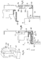
- FIG. 1A to 4D a first exemplary embodiment of a holding device is shown, with a slide 4 being shown in FIG.
- Slider receptacle 3.6 of a base part 3 shown in FIG. 1C can be inserted from top to bottom.
- the slide 4 in the inserted state defines with its lower region an angled holding section 5.1 of a holding piece 5 on a fold 1.3 of a housing 1.
- the holding piece 5 is connected to an edge of a circuit board 6, which is inserted in the direction of the arrow into a slot of a connector.
- the plug-in card 6 is secured against being released from the slot via the holding piece 5 and the slider 4 inserted into the slider receptacle 3.6, since the slider receptacle 3.6 is fixed to the base frame 1 with the base part 3.
- the slide 4 has two lateral spring legs 4.1 running in the plugging direction, which are directed perpendicular to the wall of the base frame 1 (cf., for example, FIG. 1B).
- the spring legs 4.1 are connected to one another on their underside via a connecting web 4.2.
- the connecting web 4.2 runs out into a substantially vertically downward nose 4.3 which, in the inserted state, projects into a gap 5.2 between the holding piece 5 and the facing edge of the plug-in card 6, so that the plug-in card 6 is also secured against lateral movement in the drawing plane, as can be seen in FIG. 1B.
- 1A also shows a guide web 4.8 which projects vertically on the outside of the spring legs 4.1 and points in the direction of insertion, as is provided on both spring legs 4.1.
- the guide web 4.8 On the outside facing away from the spring leg 4.1, the guide web 4.8 carries a locking element 4.4 designed as a toothing with flanks which are flat in the plugging direction and steep against the plugging direction.
- respective guide grooves 3.7 are formed in the base part 3 in the area of the slide receptacles 3.6, into which the guide webs 4.8 are inserted.
- the guide grooves 3.7 are formed by a rear wall section facing the base frame 1, by two lateral wall sections 3.9 running perpendicularly thereto and in the direction of insertion, and by front wall sections 3.1.
- counter-latching elements 3.3 which are designed as toothings, are also provided, which are adapted to the latching elements 4.4 and in which the latching elements 4.4 engage in the inserted state.
- the front wall sections 3.1 arranged in the lower, front area in the middle act as safety hooks which engage behind a section or behind a support element 4.7 of the slide 4, so that it also in the inserted state is fixed to the base part 3 in its lower region.
- the central front wall section 3.1 of the base part is connected to the rear wall section of the base part 3 via a central web 3.8.
- the lower region of the slide holder 3.6 is divided into two regions, each with two opposing guide grooves, the front wall section 3.1 leaving two recesses through which the two spring legs 4.1 protrude forwardly from the base part 3 in the inserted state.
- the spring legs 4.1 are compressed, so that the latching elements 4.4 disengage from the counter-latching elements 3.3 and the slider 4 can be pulled up out of the slider receptacle 3.6, as shown, for example, in FIG. 2.
- a tab 1.1 is bent out, which engages behind a securing section 3.4 on the upper edge of the base part 3.
- a cam 3.2 is provided, which projects into a corresponding recess 1.2 in the fold 1.3 of the base frame 1.
- Several securing elements 3.4 and corresponding tabs 1.1 as well as cams 3.2 and cutouts 1.2 are provided over the length of the base part 3.
- the base part 3 can be fixed to the base frame 1 by these measures in a kind of clip process.
- the slide 4 is integrally connected to the base part 3 via a flexible band 7.
- the flexible band 7 is connected to the slide 4 in the upper region between the two spring legs 4.1, this connection region simultaneously forming a V-shaped or U-shaped spring element 4.5.
- This leaf-shaped spring element 4.5 supports the two spring legs 4.1 against each other at their free edge, so that when the spring legs 4.1 are compressed, the legs are deflected relatively uniformly over their length and the final engagement is improved.
- the design of the spring element 4.5 can be clearly seen in particular in FIG. 3C. 3C also shows the connection of the band 7 to the base part 3 via an arcuate connection area. This design can also be seen in FIG. 4B.
- the upper outer sides of the spring legs 4.1 can also have a corrugation for better grip to form a grip area 4.6.
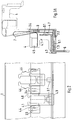
- FIGS. 5 to 7B show a further exemplary embodiment of the holding device 2.
- the fastening parts are designed as lever devices 8 in the form of a two-joint system for fixing individual cards.
- the holding section 5.1 of the holding piece 5 is overlapped by a lower joint leg 8.9 in the plugging direction of the plug-in card, which, as in the previous exemplary embodiment, has a nose 8.8 for gripping over the holding section 5.1 on its free end facing the plug-in card.
- the lower joint leg 8.9 is divided into a contact leg 8.91, which cooperates with the holding section 5.1, and a holding leg 8.92, a small, acute-angled gap being left between the contact leg 8.91 and the holding leg 8.92.
- the holding leg 8.92 is articulated at a first articulation point 8.9 to an upwardly directed support leg 8.3, which at its upper end merges into a fixing section 8.4 directed towards the base frame 1.
- the fixing section 8.4 has on its upper side at the end directed towards the base frame 1 a fixing lug 8.5 which, in the supported state, engages in a fixing receptacle 3.5 on the base part 3 (see FIGS. 5a) and 5b)).
- the holding leg 8.92 is also connected at its rear end to the lower end region of the base part 3 via a second hinge point 8.2, for example a film hinge.
- the fixing section 8.4 is snapped into the fixing receptacle 3.5, whereby the elasticity of the holding leg 8.92 and the support leg 8.3 are used.
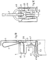
- the lever device for releasing the holding section 5.1 is pivoted upward and can be hung with a hook-like support 8.7 on an upper edge region or another suitable location on the base frame 1, so that the plug-in card can be removed or inserted unhindered.
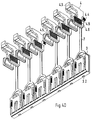
- the support 8.7 is integrally formed on the fixing section 8.4 via a web section 8.6. 6 shows in perspective several fastening parts in the form of lever devices 8, five lever devices being arranged in the support position and one lever device in the release position. These two positions are also shown in the cross-sectional representations according to FIGS. 7A and 7B.
- the base part 3 is in the form of latching hooks near the upper and lower edges of the base part by means of securing sections 3.4 ′ provided on its rear side fixed in corresponding recesses of the base frame 1, the securing portions 3.4 'having mutually directed locking hooks.
- the base frame 1 When reference is made here to the base frame 1, this expression is to be understood generally and includes various types of receptacles for plug-in cards, such as e.g. also a chassis.
- a wall or base plate of a housing can also be provided for the arrangement of slots.
Landscapes
- Engineering & Computer Science (AREA)
- Microelectronics & Electronic Packaging (AREA)
- Details Of Connecting Devices For Male And Female Coupling (AREA)
Applications Claiming Priority (2)
| Application Number | Priority Date | Filing Date | Title |
|---|---|---|---|
| DE19606797A DE19606797C2 (de) | 1995-09-07 | 1996-02-23 | Haltevorrichtung für Steckkarten |
| DE19606797 | 1996-02-23 |
Publications (1)
| Publication Number | Publication Date |
|---|---|
| EP0792003A1 true EP0792003A1 (fr) | 1997-08-27 |
Family
ID=7786233
Family Applications (1)
| Application Number | Title | Priority Date | Filing Date |
|---|---|---|---|
| EP96120311A Withdrawn EP0792003A1 (fr) | 1996-02-23 | 1996-12-18 | Dispositif de retenue pour cartes insérées |
Country Status (1)
| Country | Link |
|---|---|
| EP (1) | EP0792003A1 (fr) |
Cited By (3)
| Publication number | Priority date | Publication date | Assignee | Title |
|---|---|---|---|---|
| EP1811826A1 (fr) * | 2006-01-24 | 2007-07-25 | Hirschmann Car Communication GmbH | Boîtier d'un dispositif électronique d'un véhicule |
| CN100489733C (zh) * | 2006-06-28 | 2009-05-20 | 鸿富锦精密工业(深圳)有限公司 | 扩充卡固定装置 |
| CN114857389A (zh) * | 2022-05-06 | 2022-08-05 | 台州芮迪阀门股份有限公司 | 一种高强度分水器支架 |
Citations (4)
| Publication number | Priority date | Publication date | Assignee | Title |
|---|---|---|---|---|
| FR2618632A1 (fr) * | 1987-07-24 | 1989-01-27 | Cit Alcatel | Dispositif de verrouillage d'une carte imprimee |
| DE4403907A1 (de) | 1994-02-08 | 1995-08-10 | Vobis Microcomputer Ag | Personal-Computer mit einem Gehäuse, einer Hauptplatine, Steckkarten und einer Haltevorrichtung hierfür |
| DE19516428A1 (de) * | 1994-05-25 | 1995-11-30 | Siemens Ag | Anordnung zum Befestigen einer Steckbaugruppe |
| DE29520867U1 (de) * | 1995-09-07 | 1996-04-11 | Funk Dreidimensional Entwicklungs- und Vertriebsgesellschaft mbH, 72226 Simmersfeld | Personalcomputer mit Gehäuse, Hauptplatine, Steckkarten und einer Haltevorrichtung dafür |
-
1996
- 1996-12-18 EP EP96120311A patent/EP0792003A1/fr not_active Withdrawn
Patent Citations (4)
| Publication number | Priority date | Publication date | Assignee | Title |
|---|---|---|---|---|
| FR2618632A1 (fr) * | 1987-07-24 | 1989-01-27 | Cit Alcatel | Dispositif de verrouillage d'une carte imprimee |
| DE4403907A1 (de) | 1994-02-08 | 1995-08-10 | Vobis Microcomputer Ag | Personal-Computer mit einem Gehäuse, einer Hauptplatine, Steckkarten und einer Haltevorrichtung hierfür |
| DE19516428A1 (de) * | 1994-05-25 | 1995-11-30 | Siemens Ag | Anordnung zum Befestigen einer Steckbaugruppe |
| DE29520867U1 (de) * | 1995-09-07 | 1996-04-11 | Funk Dreidimensional Entwicklungs- und Vertriebsgesellschaft mbH, 72226 Simmersfeld | Personalcomputer mit Gehäuse, Hauptplatine, Steckkarten und einer Haltevorrichtung dafür |
Non-Patent Citations (2)
| Title |
|---|
| "ADAPTABLE CARD RETAINER", IBM TECHNICAL DISCLOSURE BULLETIN, vol. 33, no. 2, 1 July 1990 (1990-07-01), pages 103 - 105, XP000123550 * |
| "ADAPTABLE CARD RETAINER", IBM TECHNICAL DISCLOSURE BULLETIN, vol. 33, no. 2, 1 July 1990 (1990-07-01), pages 374 - 377, XP000123654 * |
Cited By (4)
| Publication number | Priority date | Publication date | Assignee | Title |
|---|---|---|---|---|
| EP1811826A1 (fr) * | 2006-01-24 | 2007-07-25 | Hirschmann Car Communication GmbH | Boîtier d'un dispositif électronique d'un véhicule |
| CN100489733C (zh) * | 2006-06-28 | 2009-05-20 | 鸿富锦精密工业(深圳)有限公司 | 扩充卡固定装置 |
| CN114857389A (zh) * | 2022-05-06 | 2022-08-05 | 台州芮迪阀门股份有限公司 | 一种高强度分水器支架 |
| CN114857389B (zh) * | 2022-05-06 | 2024-05-17 | 台州芮迪阀门股份有限公司 | 一种高强度分水器支架 |
Similar Documents
| Publication | Publication Date | Title |
|---|---|---|
| EP0017940B1 (fr) | Assemblage de connexion électrique | |
| DE2051228C3 (de) | Steckfassung für einen integrierten Schaltungsmodul | |
| DE69005665T2 (de) | An einer Oberfläche montierbarer elektrischer Verbinder. | |
| DE2800307C2 (de) | Verbindereinheit zum Verbinden mindestens eines Kontaktstifts mit einem Leiter beispielsweise eines flachen Schaltkreises | |
| DE19942753C2 (de) | Steckverbindung mit einem Befestigungshebel | |
| DE69105832T2 (de) | Elektrischer Zwischenverbinder für Leiterplatten. | |
| DE2417284C2 (de) | Rahmen zur Aufnahme von gedruckte Schaltungen aufweisenden Karten | |
| EP0793313A2 (fr) | Connecteur d'insérage à angle droit à insérer en force dans les trous d'un circuit imprimé | |
| DE2161637A1 (de) | Elektrisches Verbindungselement, insbesondere zur Anbringung an Leiterplatten | |
| DE1765441A1 (de) | Anschlussvorrichtung fuer gedruckte Schaltungen | |
| DE10150045B4 (de) | Anschlussleiste | |
| DE3435789A1 (de) | Halterungsblock zum verbinden von verbindungselementen mit der platte eines gedruckten schaltkreises | |
| DE4318509C2 (de) | Kontaktelement für elektrische Steckverbinder sowie eine Steckverbinderanordnung | |
| DE1929470A1 (de) | Elektrische Steckverbindung mit Befestigungsvorrichtung | |
| DE2835316C2 (fr) | ||
| EP0674828B1 (fr) | Dispositif a support plastique permettant de loger et de maintenir un module electronique | |
| EP0097228A1 (fr) | Mécanisme d'insertion et d'extraction pour cartes à modules électriques munies de connecteurs embrochables | |
| EP0780923B1 (fr) | Serrage pour relier une extrémité d'une âme de conducteur avec un contact | |
| DE69405883T2 (de) | Vorrichtung zum Kartenauswerfen | |
| DE2516746A1 (de) | Haltevorrichtung fuer eine auf einer gedruckten leiterplatte senkrecht angeordnete und mit dieser kontaktierten zweiten leiterplatte | |
| DE69121997T2 (de) | Metall-Raste für einen SIMM-Sockel | |
| EP3671966A1 (fr) | Connecteur enfichable direct pour une carte de circuit imprimé | |
| DE69808829T2 (de) | Elektrischer Steckverbinder | |
| DE19606797C2 (de) | Haltevorrichtung für Steckkarten | |
| DE102024134935A1 (de) | Federkraftklemmanschluss und Leiteranschlussklemme |
Legal Events
| Date | Code | Title | Description |
|---|---|---|---|
| PUAI | Public reference made under article 153(3) epc to a published international application that has entered the european phase |
Free format text: ORIGINAL CODE: 0009012 |
|
| AK | Designated contracting states |
Kind code of ref document: A1 Designated state(s): BE FR GB IE IT LU NL |
|
| 17P | Request for examination filed |
Effective date: 19980227 |
|
| STAA | Information on the status of an ep patent application or granted ep patent |
Free format text: STATUS: THE APPLICATION IS DEEMED TO BE WITHDRAWN |
|
| 18D | Application deemed to be withdrawn |
Effective date: 20030103 |