EP0792018A2 - Filtre à ondes acoustiques, filtre en échelle et radio comprenant le même, et procédé - Google Patents
Filtre à ondes acoustiques, filtre en échelle et radio comprenant le même, et procédé Download PDFInfo
- Publication number
- EP0792018A2 EP0792018A2 EP97102281A EP97102281A EP0792018A2 EP 0792018 A2 EP0792018 A2 EP 0792018A2 EP 97102281 A EP97102281 A EP 97102281A EP 97102281 A EP97102281 A EP 97102281A EP 0792018 A2 EP0792018 A2 EP 0792018A2
- Authority
- EP
- European Patent Office
- Prior art keywords
- reflector
- transducer
- shunt
- numbers
- substrate
- Prior art date
- Legal status (The legal status is an assumption and is not a legal conclusion. Google has not performed a legal analysis and makes no representation as to the accuracy of the status listed.)
- Withdrawn
Links
- 238000000034 method Methods 0.000 title claims abstract description 15
- 239000000758 substrate Substances 0.000 claims abstract description 24
- 230000008878 coupling Effects 0.000 claims description 22
- 238000010168 coupling process Methods 0.000 claims description 22
- 238000005859 coupling reaction Methods 0.000 claims description 22
- GQYHUHYESMUTHG-UHFFFAOYSA-N lithium niobate Chemical compound [Li+].[O-][Nb](=O)=O GQYHUHYESMUTHG-UHFFFAOYSA-N 0.000 claims description 5
- WSMQKESQZFQMFW-UHFFFAOYSA-N 5-methyl-pyrazole-3-carboxylic acid Chemical compound CC1=CC(C(O)=O)=NN1 WSMQKESQZFQMFW-UHFFFAOYSA-N 0.000 claims description 3
- 238000004519 manufacturing process Methods 0.000 claims description 2
- 238000003780 insertion Methods 0.000 description 14
- 230000037431 insertion Effects 0.000 description 14
- 230000004044 response Effects 0.000 description 14
- 239000000463 material Substances 0.000 description 13
- 238000013461 design Methods 0.000 description 12
- 229910003327 LiNbO3 Inorganic materials 0.000 description 7
- 230000007704 transition Effects 0.000 description 7
- 238000013459 approach Methods 0.000 description 5
- 229910012463 LiTaO3 Inorganic materials 0.000 description 4
- 238000004891 communication Methods 0.000 description 4
- 238000010586 diagram Methods 0.000 description 4
- 230000000694 effects Effects 0.000 description 4
- 230000006872 improvement Effects 0.000 description 4
- 239000003990 capacitor Substances 0.000 description 3
- 241000282320 Panthera leo Species 0.000 description 2
- 230000001413 cellular effect Effects 0.000 description 2
- PSHMSSXLYVAENJ-UHFFFAOYSA-N dilithium;[oxido(oxoboranyloxy)boranyl]oxy-oxoboranyloxyborinate Chemical compound [Li+].[Li+].O=BOB([O-])OB([O-])OB=O PSHMSSXLYVAENJ-UHFFFAOYSA-N 0.000 description 2
- 238000005516 engineering process Methods 0.000 description 2
- 238000001914 filtration Methods 0.000 description 2
- 229910052751 metal Inorganic materials 0.000 description 2
- 239000002184 metal Substances 0.000 description 2
- 238000012986 modification Methods 0.000 description 2
- 230000004048 modification Effects 0.000 description 2
- 238000005457 optimization Methods 0.000 description 2
- 230000005855 radiation Effects 0.000 description 2
- 238000002310 reflectometry Methods 0.000 description 2
- 230000003068 static effect Effects 0.000 description 2
- 238000010897 surface acoustic wave method Methods 0.000 description 2
- 230000006978 adaptation Effects 0.000 description 1
- 229910052782 aluminium Inorganic materials 0.000 description 1
- XAGFODPZIPBFFR-UHFFFAOYSA-N aluminium Chemical compound [Al] XAGFODPZIPBFFR-UHFFFAOYSA-N 0.000 description 1
- 238000004458 analytical method Methods 0.000 description 1
- 238000003491 array Methods 0.000 description 1
- 239000002131 composite material Substances 0.000 description 1
- 230000001010 compromised effect Effects 0.000 description 1
- 239000013078 crystal Substances 0.000 description 1
- 230000007547 defect Effects 0.000 description 1
- 238000000151 deposition Methods 0.000 description 1
- 230000007246 mechanism Effects 0.000 description 1
- 239000000203 mixture Substances 0.000 description 1
- 238000000059 patterning Methods 0.000 description 1
- 230000000737 periodic effect Effects 0.000 description 1
- 230000001737 promoting effect Effects 0.000 description 1
- 239000010453 quartz Substances 0.000 description 1
- 230000009467 reduction Effects 0.000 description 1
- VYPSYNLAJGMNEJ-UHFFFAOYSA-N silicon dioxide Inorganic materials O=[Si]=O VYPSYNLAJGMNEJ-UHFFFAOYSA-N 0.000 description 1
- 238000004088 simulation Methods 0.000 description 1
- 230000003595 spectral effect Effects 0.000 description 1
- 230000000638 stimulation Effects 0.000 description 1
Images


Classifications
-
- H—ELECTRICITY
- H03—ELECTRONIC CIRCUITRY
- H03H—IMPEDANCE NETWORKS, e.g. RESONANT CIRCUITS; RESONATORS
- H03H9/00—Networks comprising electromechanical or electro-acoustic elements; Electromechanical resonators
- H03H9/46—Filters
- H03H9/64—Filters using surface acoustic waves
- H03H9/6423—Means for obtaining a particular transfer characteristic
- H03H9/6433—Coupled resonator filters
- H03H9/6483—Ladder SAW filters
-
- H—ELECTRICITY
- H03—ELECTRONIC CIRCUITRY
- H03H—IMPEDANCE NETWORKS, e.g. RESONANT CIRCUITS; RESONATORS
- H03H9/00—Networks comprising electromechanical or electro-acoustic elements; Electromechanical resonators
- H03H9/25—Constructional features of resonators using surface acoustic waves
Definitions
- the present invention relates in general to surface acoustic wave filters, in particular to leaky surface wave/surface skimming bulk wave filters and more particularly to acoustic filters fabricated on high electromechanical coupling coefficient substrata.
- Filters are needed for a variety of such communications applications wherein small size, light weight and high performance are simultaneously required.
- Increasing numbers of products seek to employ fixed spectral resources, often to achieve tasks not previously envisioned. Examples include cellular telephones, inter- and intra-facility computer-computer and/or computer-ancillary equipment linkages as well as a host of other, increasingly complex inter-personal and/or -equipment information sharing requirements.
- the desire to render increasingly complicated communications nodes portable and even hand-held and/or -portable and/or pocket-sized places extreme demands on filtering technology in the context of increasingly crowded radio frequency resources.
- Acoustic wave devices provide filters meeting stringent performance requirements, which filters are (i) extremely robust, (ii) readily mass produced, (iii) adjustment-free over the life of the unit and (iv) which sharply increase the performance-to-size ratio achievable in the frequency range extending from a few tens of megahertz to about several gigahertz.
- need for low passband insertion loss simultaneously coupled with demand for high shape factor and high stopband attenuation pose filter design and performance requirements not easily met by a single acoustic wave filter alone.
- One approach to satisfying these needs and demands is to cascade two or more acoustic wave filters.
- This approach realizes increased stopband signal rejection but requires additional matching components (e.g., inductors and/or capacitors) and also multiplies the volume and weight of the acoustic wave filters by the number of such filters cascaded, when each filter is separately realized, impedance matched and packaged.
- Matching components additionally incur major size and weight penalties because each transducer generally requires at least two matching components, each of which is at least as large as an acoustic wave filter die.
- Another approach is to provide two or more such filters on a single substrate, wherein the filters are designed to have purely real impedances matched one to another without requiring intervening matching components.
- One realization includes a series-parallel arrangement of resonant elements having staggered center frequencies and arranged in a ladder structure, i.e., a structure known as a "ladder filter" and comprising cascaded sections, each including a series resonant element followed by a shunt resonant element.
- the antiresonant frequency of the shunt element is chosen to be equal to the resonant frequency of the accompanying series element.
- Disadvantages of this approach when implemented employing SAW resonators include a fixed bandwidth for the electromechanical coupling coefficient (k 2 ) associated with the chosen substrate material.
- conventional design approaches are such that when three of the filter material, impedance, selectivity and bandwidth characteristics are specified, the fourth is also determined.
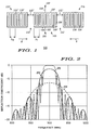
- Acoustic wave filters including ladder filters formed from groupings of resonators employ generally periodic arrays of electrodes configured to provide discrete elements such as transducers (for converting electrical to mechanical energy and vice versa), reflectors (for reversing the direction of propagation of an acoustic wave) and gaps for separating transducers and reflectors. These elements are grouped in a generally in-line configuration (e.g., reflector, gap, transducer, gap, reflector) along a principal axis of acoustic wave propagation on a suitable substrate material, with the entire array providing an electrical filtering function associated with the electrical port(s) of the individual transducer(s) and/or the composite filter.
- a generally in-line configuration e.g., reflector, gap, transducer, gap, reflector
- acoustic reflectors provide reduced insertion loss by trapping energy within a Fabry-Perot-like cavity formed about a transducer.
- Conventional acoustic reflectors include large numbers of reflection elements in order to increase the efficiency of the energy-trapping. This increases the physical size ("footprint") of the device and also reduces the bandwidth over which the reflector operates efficiently. Additionally this may result in increased ripple in the filter "skirt" regions, where the response is rapidly changing from low to high insertion loss (or vice versa) with frequency.
- the present invention provides a method and apparatus for improving tradeoffs between insertion loss and bandwidth of SAW (e.g., SAW, surface skimming bulk wave, leaky wave etc.) ladder-type filters or other acoustic wave devices fabricated on high electromechanical coupling coefficient substrata.
- SAW e.g., SAW, surface skimming bulk wave, leaky wave etc.
- ladder-type filters or other acoustic wave devices fabricated on high electromechanical coupling coefficient substrata e.g., SAW, surface skimming bulk wave, leaky wave etc.
- FIG. 1 illustrates acoustic wave resonator 100 comprising reflectors 115, 115' disposed at acoustic ports of transducer 105, one or more transducers 105 separated from reflectors 115, 115' by gaps 112, all collectively disposed in an in-line configuration along a preferred axis (e.g., as indicated by direction arrows 8, 9) of the substrate material and on a suitably-prepared surface thereof.
- reflective elements 1116, 116' may be electrically coupled together (if conductive) as illustrated or may be electrically isolated from one another or that reflectors 115, 115' may comprise a mixture of conductive or nonconductive features or may include recesses or grooves.
- Reflective elements 116, 116' are conveniently realized as metallized features formed at the same time as, and of the same material as, transducer 105.
- acoustic wavelength is taken to mean an acoustic wavelength at the filter center frequency, i.e., in the nominal center of the filter passband.
- Each transducer 105 comprises a series of periodically disposed electrodes 109, 109', often one-fourth of an acoustic wavelength in width, disposed on one-half acoustic wavelength centers, usually alternately coupled to their associated bus bars 107, 108, respectively, although other arrangements are possible and useful.
- Gaps 112 have gap breadth 112' chosen in accordance with design principles applicable to acoustic wave filters and the specifications relevant to the filter being designed. Gap breadths 112' influence passband characteristics such as bandwidth and passband ripple. Reflectors 115, 115' have a characteristic periodicity and therefore a characteristic wavelength ⁇ R while transducer 105 also has a characteristic periodicity and therefore a characteristic wavelength ⁇ T .
- both transducer 105 and reflectors 115, 115' comprises electrodes or fingers 109, 109' or 116, 116' one-fourth of a wavelength broad (as illustrated), providing two of electrodes 109, 109' or 116, 116' and two intervening gaps per wavelength, however, it will be appreciated that other arrangements are possible and in some applications are preferred.
- Resonator 100 may be constructed on suitably-prepared substrata capable of supporting acoustic wave propagation such as lithium tetraborate, 41 o rotated, Y-cut, X-propagating LiNbO 3 (lithium niobate), 64 o rotated, Y-cut, X-propagating LiNbO 3 and 36 o rotated, Y-cut, X-propagating LiTaO 3 (lithium tantalate).
- substrata capable of supporting acoustic wave propagation
- acoustic wave propagation such as lithium tetraborate, 41 o rotated, Y-cut, X-propagating LiNbO 3 (lithium niobate), 64 o rotated, Y-cut, X-propagating LiNbO 3 and 36 o rotated, Y-cut, X-propagating LiTaO 3 (lithium tantalate).
- Resonator 100 is typically fabricated by depositing and patterning a thin metal film, often comprising aluminum, in a thickness ranging from tens to hundreds of nanometers thick, by techniques similar to those employed in integrated circuit manufacturing, but are in some ways much more challenging to fabricate and much less forgiving of design rule variations and/or defects.
- the present invention is especially useful when low insertion loss is required together with wide passband width, for which higher electromechanical coupling coefficient substrata are particularly well suited.
- the designer of such a filter chooses gap widths (e.g., 112') for gaps (e.g., 112) disposed between the transducer (e.g., 105) and the reflectors (e.g., 115, 115') to provide an approximation to a combination of passband insertion loss, out-of-band rejection characteristics and bandwidth and then adjusts width(s) 112' of gap(s) 112 disposed between transducer 105 and reflectors 115, 115' to realize optimum bandwidth, insertion loss and other filter characteristics.
- Resonator 100 is conveniently modeled as a series RLC circuit (e.g., a resistor of resistance R having one lead coupled to terminal 101, in series with an inductor having inductance L, in turn coupled in series with a capacitor having capacitance C m and having a second lead coupled to terminal 102) bridged by a capacitor having capacitance C o (i.e., coupled from terminal 101 to terminal 102).
- a series RLC circuit e.g., a resistor of resistance R having one lead coupled to terminal 101, in series with an inductor having inductance L, in turn coupled in series with a capacitor having capacitance C m and having a second lead coupled to terminal 102
- C o i.e., coupled from terminal 101 to terminal 102
- Values for components C o , C m , L, R are found from Eqs. 1-3 (infra), the geometry of transducer 105 and relevant material constants. R may be usefully estimated as zero (i.e., ignored
- R represents bulk wave radiation, acoustic propagation away from the receiving transducer, metal resistivity, diffraction effects and other losses encountered in acoustic resonant elements.
- antiresonant frequency ⁇ a is always greater than resonant frequency ⁇ r by a ratio determined by electromechanical coupling coefficient k 2 (Eq. 7).
- electromechanical coupling coefficient k 2 Eq. 7
- an appropriate coupling coefficient value may need to be empirically determined because the assumptions employed in relating physical parameters (e.g., acoustic wavelength, radiation conductance, ⁇ a , ⁇ r etc.) to each other and to acoustic center frequencies are not entirely valid.
- coupling coefficients are generally usefully greater than 0.0001, more usefully greater than 0.01, generally desirably greater than 0.05, more desirably greater than 0.07 and preferably greater than 0.10.
- Ladder filters typically employ elements wherein the resonant frequencies of the series elements are chosen to be equal to the antiresonant frequencies of the shunt elements.
- electromechanical coupling coefficient k 2 is typically much smaller than 0.5%, limiting the fractional bandwidth (bandwidth divided by center frequency) achievable for such filters to very small values.
- FIG. 2 is a graph of frequency responses for several different acoustic reflectors.
- Trace 201 corresponds to a reflector 115, 115' including 100 reflective elements 116, 116';
- trace 203 corresponds to a reflector 115, 115' including 25 reflective elements 116, 116' and trace 205 corresponds to a reflector 115, 115' including only ten reflective elements 116, 116'.
- series and shunt elements' resonant ⁇ r and antiresonant ⁇ a frequencies are usefully determined via circuit optimization tools such as SuperCompact®, available from Compact Software of Paterson NJ.
- One method is to input a series of resonant ⁇ r and/or antiresonant ⁇ a frequencies in accordance with Eq. 7, with the shunt elements' antiresonant frequencies ⁇ a approximately equal to the series elements' resonant frequencies ⁇ r and to then enable the circuit optimization tools to determine a modified set of resonant ⁇ r and antiresonant ⁇ a frequencies.
- Ladder filters using surface acoustic wave resonators and especially resonators designed for relatively wide-band performance may be readily scaled in frequency by changing the pitch (periodicity) of the resonator transducer fingers (109, 109', FIG. 1) and reflection elements or fingers (116, 116') while maintaining the ratios of the resonant frequencies ⁇ r obtained from circuit analysis tools or other methods.
- FIG. 3 is a block diagram of ladder filter 400 in accordance with an exemplary embodiment of the instant invention.
- Ladder filter 400 includes electrical ports 401, 401' each coupled to transducer 403, 403', respectively, via interconnections 402, 402', respectively.
- Transducers 403, 403' each couple to shunt transducers 404, 404', respectively, and also each couple to series transducers 405, 405', respectively.
- Series transducers 405, 405' each couple to shunt transducers 406, 406', respectively, and also each couple to series transducer 410, coupling the two halves of filter 400 together.
- Transducers 403, 403', 404, 404', 405, 405', 406, 406', 410 each correspond to resonator 100, FIG. 1.
- FIG. 4 provides (i) a graphical depiction of measured frequency responses for ladder filters similar to that of FIG. 3, where the filters incorporate different sizes of gratings 115, 115' and (ii) a graph of a response for a device having no gratings.
- These devices each used nine resonators, five as series resonators 403, 403', 405, 405', 410 and four as shunt resonators 404, 404', 406, 406'.
- Series resonators 403, 403', 405, 405', 410 incorporated 251 transducer electrodes and shunt transducers 404, 404', 406, 406' incorporated 301 electrodes.
- Gaps 112 FIG.
- Trace 420 is a measured frequency response for a filter including no reflectors; trace 422 is a measured frequency response for a filter having ten reflection elements 116, 116' in each reflector 115, 115'; and trace 424 is a measured frequency response for a filter having twenty-five reflection elements 116, 116' in each reflector 115, 115'.
- Comparison of traces 420, 422, 424 shows that the first ten reflector elements 116, 116' provide the lion's share of the improvement in insertion loss, with the additional 15 elements in the device of trace 424 providing substantially less improvement in insertion loss.
- Experimentally measured passband width, high- and low-frequency band transition widths and number of reflectors are summarized below in Table I for the data of FIG. 4.
- Table I Bandwidths and number of reflection elements (all bandwidths are given in megahertz). No. of Elements Passband width High side transition width Low side transition width None 18.7 11.5 15.3 10 28.3 8.4 8.4 25 30.2 6.6 6.4 These filters were designed to meet a specification calling for less than 4.5 dB of insertion loss across a 19 MHz passband, increasing to > 10 dB of rejection within ⁇ 17.5 MHz on the high frequency side.
- the data of Table I show that the designs with optimized reflector structures have greater passband widths and narrower transition widths than the reflectorless design, giving them greater margins for meeting specifications.
- FIG. 5 is a graph of simulated frequency responses for ladder filters including differing numbers of reflection elements.
- Trace 501 is a simulation of a ladder filter response for a device having no reflectors; trace 502 corresponds to a device including 15 reflection elements 116, 116' (FIG. 1); and trace 503 corresponds to a device having 100 reflection elements 116, 116'.
- the majority or lion's share of the insertion loss reduction occurs (traces 501, 502) for the first few reflection elements 116, 116', with relatively little improvement resulting from inclusion of the remainder (see trace 503).
- the passband bandwidth and the transition band sharpness are both compromised in comparison to those of traces 501, 502. When transition bandwidth, passband insertion loss and passband bandwidth are all concerns, it is clear that an optimal number of reflection elements (e.g., 116, 116') may be chosen. For high coupling coefficient substrata, this may be determined as follows.
- BW R (Ak 2 / ⁇ )(1 + (2 ⁇ /N g k 2 ) 2 ) 0.5 .
- the number N g of reflection elements 116, 116' (FIG. 1) is usefully in a range of from five to seventy five, preferably in a range of from seven to seventy and desirably in a range of from nine to about fifty five.
- FIG. 6 is a block diagram of portion 1800 of a radio frequency receiver or other radio frequency apparatus including ladder filters in accordance with the present invention.
- Apparatus 1800 includes antenna 1801, by way of example, used to receive and/or transmit signals.
- antenna 1801 could be replaced by a fiber-optic link or cable or other signal transmissive media.
- Diplexer 1803 is coupled to antenna 1801 and to a transmitter portion (not shown).
- Diplexer 1803 is a special purpose filter which couples received signals (but not much larger signals from an attached transmitter) to filter 1807 via optional matching circuit 1805 according to the present invention.
- Filter 1807 is coupled to amplifier 1811 via optional matching element 1809.
- the output of amplifier 1811 is transmitted to filter 1815 via optional matching element 1813.
- Filter 1815 transmits its output to mixer 1819 via optional matching element 1817.
- the signal from filter 1815 is combined in mixer 1819 with another signal from local oscillator 1825 coupled via filter 1829.
- Matching elements 1827, 1831 and 1821 are optionally provided with filters 1823, 1829.
- the output signal from mixer 1819 is then filtered by filter 1823 to provide the IF output signal.
- the arrangement of the present invention may be used to provide any or all of filters 1803, 1807, 1815, 1823, 1829.
- An oscillator and filter analogous to LO 1825, filter 1829 may be employed together with a suitable amplifier and modulator to provide the signal "FROM TRANSMITTER” and this filter (known as a “transmit clean-up filter”) as well may be provided in accordance with the present invention.
- a ladder filter has been described which overcomes specific problems and accomplishes certain advantages relative to prior art methods and mechanisms. The improvements over known technology are significant. The expense, complexities, and high parts count of prior art cascaded filters are avoided. Further, real input and output impedances are realized for compact, lightweight, adjustment-free filters together with improved design flexibility.
Landscapes
- Physics & Mathematics (AREA)
- Acoustics & Sound (AREA)
- Surface Acoustic Wave Elements And Circuit Networks Thereof (AREA)
Applications Claiming Priority (2)
| Application Number | Priority Date | Filing Date | Title |
|---|---|---|---|
| US603523 | 1996-02-20 | ||
| US08/603,523 US6172582B1 (en) | 1996-02-20 | 1996-02-20 | Saw resonator and ladder filter with specified number of reflector electrode fingers |
Publications (2)
| Publication Number | Publication Date |
|---|---|
| EP0792018A2 true EP0792018A2 (fr) | 1997-08-27 |
| EP0792018A3 EP0792018A3 (fr) | 1998-05-20 |
Family
ID=24415801
Family Applications (1)
| Application Number | Title | Priority Date | Filing Date |
|---|---|---|---|
| EP97102281A Withdrawn EP0792018A3 (fr) | 1996-02-20 | 1997-02-13 | Filtre à ondes acoustiques, filtre en échelle et radio comprenant le même, et procédé |
Country Status (3)
| Country | Link |
|---|---|
| US (1) | US6172582B1 (fr) |
| EP (1) | EP0792018A3 (fr) |
| JP (1) | JPH09232905A (fr) |
Cited By (2)
| Publication number | Priority date | Publication date | Assignee | Title |
|---|---|---|---|---|
| EP1039633A3 (fr) * | 1999-03-19 | 2002-08-21 | Murata Manufacturing Co., Ltd. | Dispositif à ondes acoustiques de surface du type à réflection sur le bord |
| CN113964513A (zh) * | 2021-10-25 | 2022-01-21 | 国网天津市电力公司电力科学研究院 | 一种无线通信微波天线及其成型方法 |
Families Citing this family (46)
| Publication number | Priority date | Publication date | Assignee | Title |
|---|---|---|---|---|
| JP3432492B2 (ja) * | 2000-09-28 | 2003-08-04 | 富士通株式会社 | 弾性表面波共振器及びこれを用いた弾性表面波フィルタ |
| JP2003188675A (ja) * | 2001-12-19 | 2003-07-04 | Alps Electric Co Ltd | 表面弾性波素子及びそれを備えたデュプレクサ |
| JP2004165879A (ja) * | 2002-11-12 | 2004-06-10 | Alps Electric Co Ltd | 弾性表面波素子 |
| DE102004063121A1 (de) * | 2004-12-22 | 2006-07-13 | Junghans Uhren Gmbh | Funkarmbanduhr mit Metallzifferblatt |
| JP4148220B2 (ja) * | 2005-01-06 | 2008-09-10 | エプソントヨコム株式会社 | 弾性表面波デバイス、複合デバイス、発振回路およびモジュール |
| DE102006023165B4 (de) * | 2006-05-17 | 2008-02-14 | Infineon Technologies Ag | Verfahren zur Herstellung eines akustischen Spiegels aus alternierend angeordneten Schichten hoher und niedriger akustischer Impedanz |
| US11323090B2 (en) | 2018-06-15 | 2022-05-03 | Resonant Inc. | Transversely-excited film bulk acoustic resonator using Y-X-cut lithium niobate for high power applications |
| US12237826B2 (en) | 2018-06-15 | 2025-02-25 | Murata Manufacturing Co., Ltd. | Transversely-excited film bulk acoustic resonator with optimized electrode thickness, mark, and pitch |
| US11509279B2 (en) | 2020-07-18 | 2022-11-22 | Resonant Inc. | Acoustic resonators and filters with reduced temperature coefficient of frequency |
| US12040779B2 (en) * | 2020-04-20 | 2024-07-16 | Murata Manufacturing Co., Ltd. | Small transversely-excited film bulk acoustic resonators with enhanced Q-factor |
| US11929731B2 (en) | 2018-02-18 | 2024-03-12 | Murata Manufacturing Co., Ltd. | Transversely-excited film bulk acoustic resonator with optimized electrode mark, and pitch |
| US11323096B2 (en) | 2018-06-15 | 2022-05-03 | Resonant Inc. | Transversely-excited film bulk acoustic resonator with periodic etched holes |
| US11323089B2 (en) | 2018-06-15 | 2022-05-03 | Resonant Inc. | Filter using piezoelectric film bonded to high resistivity silicon substrate with trap-rich layer |
| US12088281B2 (en) | 2021-02-03 | 2024-09-10 | Murata Manufacturing Co., Ltd. | Transversely-excited film bulk acoustic resonator with multi-mark interdigital transducer |
| US11264966B2 (en) | 2018-06-15 | 2022-03-01 | Resonant Inc. | Solidly-mounted transversely-excited film bulk acoustic resonator with diamond layers in Bragg reflector stack |
| US11329628B2 (en) | 2020-06-17 | 2022-05-10 | Resonant Inc. | Filter using lithium niobate and lithium tantalate transversely-excited film bulk acoustic resonators |
| US11323095B2 (en) | 2018-06-15 | 2022-05-03 | Resonant Inc. | Rotation in XY plane to suppress spurious modes in XBAR devices |
| US12463619B2 (en) | 2018-06-15 | 2025-11-04 | Murata Manufacturing Co., Ltd. | Filter device |
| US10917072B2 (en) | 2019-06-24 | 2021-02-09 | Resonant Inc. | Split ladder acoustic wave filters |
| US12237827B2 (en) | 2018-06-15 | 2025-02-25 | Murata Manufacturing Co., Ltd. | Solidly-mounted transversely-excited film bulk acoustic filters with multiple piezoelectric plate thicknesses |
| US12155374B2 (en) | 2021-04-02 | 2024-11-26 | Murata Manufacturing Co., Ltd. | Tiled transversely-excited film bulk acoustic resonator high power filters |
| US11349452B2 (en) | 2018-06-15 | 2022-05-31 | Resonant Inc. | Transversely-excited film bulk acoustic filters with symmetric layout |
| US12341490B2 (en) | 2020-04-20 | 2025-06-24 | Murata Manufacturing Co., Ltd. | Low loss transversely-excited film bulk acoustic resonators and filters |
| US12278617B2 (en) | 2020-04-20 | 2025-04-15 | Murata Manufacturing Co., Ltd. | High Q solidly-mounted transversely-excited film bulk acoustic resonators |
| US11811391B2 (en) | 2020-05-04 | 2023-11-07 | Murata Manufacturing Co., Ltd. | Transversely-excited film bulk acoustic resonator with etched conductor patterns |
| US11271539B1 (en) | 2020-08-19 | 2022-03-08 | Resonant Inc. | Transversely-excited film bulk acoustic resonator with tether-supported diaphragm |
| US11405017B2 (en) | 2020-10-05 | 2022-08-02 | Resonant Inc. | Acoustic matrix filters and radios using acoustic matrix filters |
| US11728784B2 (en) | 2020-10-05 | 2023-08-15 | Murata Manufacturing Co., Ltd. | Transversely-excited film bulk acoustic resonator matrix filters with split die sub-filters |
| US11658639B2 (en) | 2020-10-05 | 2023-05-23 | Murata Manufacturing Co., Ltd. | Transversely-excited film bulk acoustic resonator matrix filters with noncontiguous passband |
| US11476834B2 (en) | 2020-10-05 | 2022-10-18 | Resonant Inc. | Transversely-excited film bulk acoustic resonator matrix filters with switches in parallel with sub-filter shunt capacitors |
| US12255617B2 (en) | 2020-11-11 | 2025-03-18 | Murata Manufacturing Co., Ltd. | Solidly-mounted transversely-excited film bulk acoustic resonators with low thermal impedance |
| US11496113B2 (en) | 2020-11-13 | 2022-11-08 | Resonant Inc. | XBAR devices with excess piezoelectric material removed |
| US12255626B2 (en) | 2020-11-13 | 2025-03-18 | Murata Manufacturing Co., Ltd. | Solidly-mounted transversely-excited film bulk acoustic filters with excess piezoelectric material removed |
| US12289099B2 (en) | 2021-03-24 | 2025-04-29 | Murata Manufacturing Co., Ltd. | Acoustic filters with shared acoustic tracks for series and shunt resonators |
| US12348216B2 (en) | 2021-03-24 | 2025-07-01 | Murata Manufacturing Co., Ltd. | Acoustic filters with shared acoustic tracks and cascaded series resonators |
| US12355426B2 (en) | 2021-03-24 | 2025-07-08 | Murata Manufacturing Co., Ltd. | Acoustic filters with shared acoustic tracks |
| CN120454674A (zh) | 2021-03-30 | 2025-08-08 | 株式会社村田制作所 | 使用横向激发薄膜体声谐振器的用于6 GHz WI-FI的滤波器 |
| US12249971B2 (en) | 2021-04-02 | 2025-03-11 | Murata Manufacturing Co., Ltd. | Transversely-excited film bulk acoustic resonators with solidly mounted resonator (SMR) pedestals |
| US12255633B2 (en) | 2021-04-16 | 2025-03-18 | Murata Manufacturing Co., Ltd. | Filter using transversely-excited film bulk acoustic resonators |
| US12160220B2 (en) | 2021-04-30 | 2024-12-03 | Murata Manufacturing Co., Ltd. | Transversely-excited film bulk acoustic resonator with oxide strip acoustic confinement structures |
| US12255630B2 (en) | 2021-04-30 | 2025-03-18 | Murata Manufacturing Co., Ltd. | Transversely-excited film bulk acoustic resonator with oxide strip acoustic confinement structures |
| US12255607B2 (en) | 2021-04-30 | 2025-03-18 | Murata Manufacturing Co., Ltd. | Transversely-excited film bulk acoustic resonator with buried oxide strip acoustic confinement structures |
| US12603639B2 (en) | 2021-08-02 | 2026-04-14 | Murata Manufacturing Co., Ltd. | Metal cavity for transversely-excited film bulk acoustic resonator (XBAR) |
| US12456962B2 (en) | 2021-09-24 | 2025-10-28 | Murata Manufacturing Co., Ltd. | Transversely-excited film bulk acoustic resonators wafer-level packaging using a dielectric cover |
| US12451864B2 (en) | 2021-09-29 | 2025-10-21 | Murata Manufacturing Co., Ltd. | Transversely-excited film bulk acoustic resonators with curved shaped ends of fingers or opposing busbars |
| US12407326B2 (en) | 2021-11-04 | 2025-09-02 | Murata Manufacturing Co., Ltd. | Stacked die transversely-excited film bulk acoustic resonator (XBAR) filters |
Family Cites Families (20)
| Publication number | Priority date | Publication date | Assignee | Title |
|---|---|---|---|---|
| US4048594A (en) * | 1976-01-02 | 1977-09-13 | Hughes Aircraft Company | Surface acoustic wave filter |
| US4144507A (en) | 1976-09-29 | 1979-03-13 | Texas Instruments Incorporated | Surface acoustic wave resonator incorporating coupling transducer into reflecting arrays |
| US4130813A (en) | 1977-05-23 | 1978-12-19 | Raytheon Company | Surface wave device having enhanced reflectivity gratings |
| US4410823A (en) | 1981-11-13 | 1983-10-18 | Zenith Radio Corporation | Surface acoustic wave device employing reflectors |
| US4454488A (en) * | 1982-07-08 | 1984-06-12 | R F Monolithics, Inc. | Surface acoustic wave resonator with middle grating |
| JPS59131213A (ja) | 1982-07-26 | 1984-07-28 | Toyo Commun Equip Co Ltd | 高周波狭帯域多重モ−ド・フイルタ |
| US4625208A (en) | 1983-06-30 | 1986-11-25 | X-Cyte Inc. | Surface acoustic wave passive transponder having acoustic wave reflectors |
| GB8327551D0 (en) | 1983-10-14 | 1983-11-16 | Secr Defence | Acoustic transducer |
| GB2149253A (en) | 1983-10-31 | 1985-06-05 | Philips Electronic Associated | Surface acoustic wave device |
| DE3485015D1 (de) | 1983-12-15 | 1991-10-10 | Toshiba Kawasaki Kk | Akustischer oberflaechenwellenresonator. |
| JPH0646692B2 (ja) | 1986-01-10 | 1994-06-15 | 株式会社日立製作所 | 弾性表面波共振子 |
| JPH01157109A (ja) | 1987-12-14 | 1989-06-20 | Hitachi Ltd | 弾性表面波共振器 |
| JPH0385807A (ja) | 1989-08-29 | 1991-04-11 | Murata Mfg Co Ltd | 弾性表面波発振子 |
| JPH03261210A (ja) * | 1990-03-12 | 1991-11-21 | Seiko Epson Corp | Saw共振子 |
| JP2645674B2 (ja) | 1990-10-15 | 1997-08-25 | 国際電気株式会社 | 弾性表面波共振子 |
| US5223762A (en) | 1990-12-27 | 1993-06-29 | Murata Manufacturing Co., Ltd. | Surface acoustic wave filter |
| JP2800905B2 (ja) * | 1991-10-28 | 1998-09-21 | 富士通株式会社 | 弾性表面波フィルタ |
| US5274345A (en) | 1992-05-13 | 1993-12-28 | Andersen Laboratories | Dual function reflector structures for interdigital saw transducer |
| DE4431612C2 (de) * | 1993-09-06 | 1998-07-16 | Sanyo Electric Co | Akustisches Oberflächenwellenfilter |
| US5471178A (en) * | 1994-02-03 | 1995-11-28 | Motorola, Inc. | Ladder filter and method for producing conjugately matched impedance |
-
1996
- 1996-02-20 US US08/603,523 patent/US6172582B1/en not_active Expired - Fee Related
-
1997
- 1997-02-13 EP EP97102281A patent/EP0792018A3/fr not_active Withdrawn
- 1997-02-18 JP JP9049885A patent/JPH09232905A/ja active Pending
Non-Patent Citations (1)
| Title |
|---|
| None |
Cited By (3)
| Publication number | Priority date | Publication date | Assignee | Title |
|---|---|---|---|---|
| EP1039633A3 (fr) * | 1999-03-19 | 2002-08-21 | Murata Manufacturing Co., Ltd. | Dispositif à ondes acoustiques de surface du type à réflection sur le bord |
| CN113964513A (zh) * | 2021-10-25 | 2022-01-21 | 国网天津市电力公司电力科学研究院 | 一种无线通信微波天线及其成型方法 |
| CN113964513B (zh) * | 2021-10-25 | 2024-01-26 | 国网天津市电力公司电力科学研究院 | 一种无线通信微波天线及其成型方法 |
Also Published As
| Publication number | Publication date |
|---|---|
| US6172582B1 (en) | 2001-01-09 |
| EP0792018A3 (fr) | 1998-05-20 |
| JPH09232905A (ja) | 1997-09-05 |
Similar Documents
| Publication | Publication Date | Title |
|---|---|---|
| US6172582B1 (en) | Saw resonator and ladder filter with specified number of reflector electrode fingers | |
| US5471178A (en) | Ladder filter and method for producing conjugately matched impedance | |
| US5933062A (en) | Acoustic wave ladder filter with effectively increased coupling coefficient and method of providing same | |
| US6201457B1 (en) | Notch filter incorporating saw devices and a delay line | |
| CN109600125B (zh) | 滤波器 | |
| US5638036A (en) | Acoustic wave ladder filter with unequal series and shunt transducer periodicities and method of making | |
| EP0718970B1 (fr) | Filtre à ondes acoustiques de surface | |
| US5854579A (en) | Saw filter using low-pass configuration and method of providing the same | |
| US5334960A (en) | Conjugately matched acoustic wave transducers and method | |
| EP0652637B1 (fr) | Filtre à ondes acoustiques de surface | |
| AU779050B2 (en) | Programmable surface acoustic wave (SAW) filter | |
| KR100290803B1 (ko) | 탄성표면파장치 | |
| US6034577A (en) | Integrated interdigital electrode saw filter with specified distances between input/output electrodes | |
| US7170370B2 (en) | Filter device capable of obtaining attenuation characteristic of sharpness in narrow band width and branching filter using the same | |
| CN1263647A (zh) | 具有改善的边缘陡度的表面声波滤波器 | |
| US5949306A (en) | Saw ladder filter with split resonators and method of providing same | |
| US5600287A (en) | Acoustic wave filter with reduced bulk-wave scattering loss, ladder filter incorporating same and method | |
| US5760664A (en) | Acoustic wave filter with double reflective gratings and method for producing the same | |
| WO2005050837A1 (fr) | Filtre d'onde elastique de surface | |
| US6828879B2 (en) | Longitudinal coupled multiple mode surface acoustic wave filter | |
| JPH10150342A (ja) | 弾性表面波フィルタおよび通過周波数帯域の形成方法 | |
| US5635883A (en) | Acoustic wave filter with filter-shaping element and method | |
| WO1998034345A1 (fr) | Resonateur couple en ligne comportant un filtre en treillis et procede afferent |
Legal Events
| Date | Code | Title | Description |
|---|---|---|---|
| PUAI | Public reference made under article 153(3) epc to a published international application that has entered the european phase |
Free format text: ORIGINAL CODE: 0009012 |
|
| AK | Designated contracting states |
Kind code of ref document: A2 Designated state(s): DE DK FI FR GB |
|
| PUAL | Search report despatched |
Free format text: ORIGINAL CODE: 0009013 |
|
| AK | Designated contracting states |
Kind code of ref document: A3 Designated state(s): DE DK FI FR GB |
|
| RBV | Designated contracting states (corrected) |
Designated state(s): DE DK FI FR GB |
|
| 17P | Request for examination filed |
Effective date: 19981120 |
|
| RAP1 | Party data changed (applicant data changed or rights of an application transferred) |
Owner name: CTS CORPORATION |
|
| 17Q | First examination report despatched |
Effective date: 20010730 |
|
| STAA | Information on the status of an ep patent application or granted ep patent |
Free format text: STATUS: THE APPLICATION IS DEEMED TO BE WITHDRAWN |
|
| 18D | Application deemed to be withdrawn |
Effective date: 20011211 |