EP0792034A2 - Optische Übertragungseinrichtung, WDM optische Übertragungsvorrichtung und optisches Übertragungssystem mit optischen RZ-Pulsen - Google Patents
Optische Übertragungseinrichtung, WDM optische Übertragungsvorrichtung und optisches Übertragungssystem mit optischen RZ-Pulsen Download PDFInfo
- Publication number
- EP0792034A2 EP0792034A2 EP97102682A EP97102682A EP0792034A2 EP 0792034 A2 EP0792034 A2 EP 0792034A2 EP 97102682 A EP97102682 A EP 97102682A EP 97102682 A EP97102682 A EP 97102682A EP 0792034 A2 EP0792034 A2 EP 0792034A2
- Authority
- EP
- European Patent Office
- Prior art keywords
- optical
- transmission
- pulses
- wavelength
- modulator
- Prior art date
- Legal status (The legal status is an assumption and is not a legal conclusion. Google has not performed a legal analysis and makes no representation as to the accuracy of the status listed.)
- Withdrawn
Links
Images



Classifications
-
- H—ELECTRICITY
- H04—ELECTRIC COMMUNICATION TECHNIQUE
- H04B—TRANSMISSION
- H04B10/00—Transmission systems employing electromagnetic waves other than radio-waves, e.g. infrared, visible or ultraviolet light, or employing corpuscular radiation, e.g. quantum communication
- H04B10/50—Transmitters
- H04B10/501—Structural aspects
- H04B10/503—Laser transmitters
- H04B10/505—Laser transmitters using external modulation
-
- H—ELECTRICITY
- H04—ELECTRIC COMMUNICATION TECHNIQUE
- H04B—TRANSMISSION
- H04B10/00—Transmission systems employing electromagnetic waves other than radio-waves, e.g. infrared, visible or ultraviolet light, or employing corpuscular radiation, e.g. quantum communication
- H04B10/50—Transmitters
- H04B10/501—Structural aspects
- H04B10/503—Laser transmitters
- H04B10/505—Laser transmitters using external modulation
- H04B10/5051—Laser transmitters using external modulation using a series, i.e. cascade, combination of modulators
-
- H—ELECTRICITY
- H04—ELECTRIC COMMUNICATION TECHNIQUE
- H04B—TRANSMISSION
- H04B10/00—Transmission systems employing electromagnetic waves other than radio-waves, e.g. infrared, visible or ultraviolet light, or employing corpuscular radiation, e.g. quantum communication
- H04B10/50—Transmitters
- H04B10/501—Structural aspects
- H04B10/506—Multiwavelength transmitters
-
- H—ELECTRICITY
- H04—ELECTRIC COMMUNICATION TECHNIQUE
- H04B—TRANSMISSION
- H04B10/00—Transmission systems employing electromagnetic waves other than radio-waves, e.g. infrared, visible or ultraviolet light, or employing corpuscular radiation, e.g. quantum communication
- H04B10/50—Transmitters
- H04B10/508—Pulse generation, e.g. generation of solitons
-
- H—ELECTRICITY
- H04—ELECTRIC COMMUNICATION TECHNIQUE
- H04J—MULTIPLEX COMMUNICATION
- H04J14/00—Optical multiplex systems
- H04J14/02—Wavelength-division multiplex systems
Definitions
- the present invention relates to an optical transmission device using return-to-zero optical pulses as transmission optical pulses, which is capable of enhancing a transmission distance as well as a wavelength range with satisfactory transmission characteristics and enabling an easy realization of the wavelength division multiplexing optical transmission.
- the present invention also relates to a wavelength division multiplexing (WDM) optical transmission apparatus and an optical transmission system formed by utilizing such an optical transmission device.
- WDM wavelength division multiplexing
- this optical soliton transmission is associated with a random variation of optical signal wavelength due to optical amplifier noises and a nonlinear effect of optical fibers, and a random jitter (known as Gordon Haus dynamic jitter) of pulse arrival time at a receiving terminal due to dispersion by optical fibers, and there has been a problem that a transmission distance is limited because of these random timing jitters.
- a random jitter known as Gordon Haus dynamic jitter
- this scheme limits the optimum wavelength range so that, in a case of multiple wavelengths transmission, the accumulated residual dispersion becomes large for long wavelength signals and it is difficult to realize a long distance transmission.
- this scheme causes an excessive spectrum spread, so that there is a need to use a large wavelength interval in order to avoid interferences among different wavelengths, even when the dispersion slope of optical fibers is compensated to realize a nearly optimum value for the residual dispersion at each wavelength, and for this reason, there is a problem that it is difficult to utilize the optical amplifier bandwidth efficiently.
- WDM wavelength division multiplexing
- an optical transmission device comprising: an optical transmitter for transmitting transmission optical pulses by superposing digital data signals onto return-to-zero optical pulses; and modulator means for applying one of a phase modulation and a frequency modulation in synchronization with a transmission rate of the transmission optical pulses, to the transmission optical pulses transmitted by the optical transmitter.
- a wavelength division multiplexing optical transmission apparatus comprising: a plurality of optical transmitters for generating respective transmission optical pulses in different wavelengths according to a wavelength division multiplexing scheme by superposing respective digital data signals onto return-to-zero optical pulses; and a plurality of modulator means, respectively connected with said plurality of optical transmitters, for applying one of a phase modulation and a frequency modulation in synchronization with transmission rates of the respective transmission optical pulses, to the respective transmission optical pulses transmitted by the respective optical transmitters.
- an optical transmission system comprising: an optical transmission device formed by an optical transmitter for transmitting transmission optical pulses by superposing digital data signals onto return-to-zero optical pulses, and modulator means for applying one of a phase modulation and a frequency modulation in synchronization with a transmission rate of the transmission optical pulses, to the transmission optical pulses transmitted by the optical transmitter; an optical receiver for receiving the transmission optical pulses transmitted from the optical transmission device; transmission optical fibers for connecting the optical transmission device and the optical receiver: and a plurality of optical amplifier repeaters provided on the transmission optical fibers, for compensating a loss of the transmission optical fibers.
- an optical transmission system comprising: a plurality of optical transmission devices formed by a plurality of optical transmitters for transmitting respective transmission optical pulses in different wavelengths according to a wavelength division multiplexing scheme by superposing respective digital data signals onto return-to-zero optical pulses, and a plurality of modulator means, respectively connected with said plurality of optical transmitters, for applying one of a phase modulation and a frequency modulation in synchronization with transmission rates of the respective transmission optical pulses, to the respective transmission optical pulses transmitted by the respective optical transmitters; a plurality of optical receivers, provided in correspondence to said plurality of optical transmission devices, for receiving the transmission optical pulses in respective wavelengths transmitted from the respective optical transmission devices; transmission optical fibers for connecting said plurality of optical transmission devices and said plurality of optical receivers; and a plurality of optical amplifier repeaters provide on the transmission optical fibers, for compensating a loss of the transmission optical fibers.
- Fig. 1 is a block diagram of an overall configuration of an optical transmission system according to the first embodiment of the present invention.
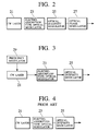
- Fig. 2 is a block diagram of one exemplary internal configuration of an optical pulse transmitter in the optical transmission system of Fig. 1.
- Fig. 3 is a block diagram of another exemplary internal configuration of an optical pulse transmitter in the optical transmission system of Fig. 1.
- Fig. 4 is a block diagram of a conventional optical transmitter for comparison purpose.
- Fig. 5 is a graph of a transmission distance versus a system mean dispersion value for a case of using the optical pulse transmitter of Fig. 2 and a case of using the conventional optical transmitter of Fig. 4.
- Fig. 6 is a block diagram of an overall configuration of an optical transmission system according to the second embodiment of the present invention.
- Fig. 7 is a graph showing an optical transmission wavelength characteristic of a Fabry-Pérot type optical filter used in the optical transmission system of Fig. 6.
- Fig. 1 shows an overall configuration of the optical transmission system in this first embodiment, where transmission optical pulses transmitted from a 20 Gbit/s return-to-zero (RZ) optical pulse transmitter 1 (hereafter simplified as optical pulse transmitter) are propagated through transmission optical fibers 5, optical amplifier repeaters 7, and dispersion compensation optical fibers 9, and received by a 20 Gbit/s optical receiver 11.
- RZ return-to-zero
- the optical pulse transmitter 1 can have an internal configuration as shown in Fig. 2 or Fig. 3, where Fig. 2 shows an exemplary configuration using an optical phase modulator 27 which will be described in detail first, while Fig. 3 shows an exemplary configuration using a frequency modulator 29 which will be described in detail later.
- Fig. 4 shows a typical configuration of a conventional optical transmitter for the sake of comparison. In these Fig. 2, Fig. 3, and Fig. 4, the similar components are identified by the same labels and reference numerals.
- the optical pulse transmitter 1 comprises a CW (Continuous Wave) laser 21, an electro-absorption type optical modulator 23, an optical intensity modulator 25, and an optical phase modulator 27, which are connected in series in this order.
- the optical phase modulator 27 is provided by a phase modulator using monocrystalline LiNbO 3 , which is driven by sinusoidal waves of 20 GHz.
- the electro-absorption type optical modulator 23 is provided by InGaAsP electro-absorption type optical modulator, which is modulated by sinusoidal waves of 20 GHz.
- this configuration of Fig. 2 differs from the conventional optical transmitter of Fig. 4 by incorporating the optical phase modulator 27.
- the DFB (Distributed FeedBack) laser output light which is continuously oscillating at 1550 nm wavelength band is outputted from the CW laser 21, and this DFB laser output light is converted into the return-to-zero optical pulse sequence which is repeating at 20 GHz by the electro-absorption type optical modulator 23, and 20 Gbit/s digital data signals are superposed onto the return-to-zero optical pulse sequence by the optical intensity modulator 25, so as to generate 20 Gbit/s pseudo-random optical signals.
- the transmission optical pulses transmitted from the 20 Gbit/s return-to-zero optical pulse transmitter 1 are the return-to-zero optical pulses having a timewise waveform with a full width at half maximum equal to 10 ps.
- the transmission optical fibers 5 have a total length equal to approximately 9000 km, and a mean zero dispersion wavelength equal to 1553.7 nm which is shorter than the signal light wavelength of 1558 nm.
- the transmission optical fibers 5 also have a mean wavelength dispersion value D equal to 0.3 ps/km/nm at the wavelength 1558 nm, and a dispersion slope (or a third-order wavelength dispersion) equal to 0.07 ps/km/nm 2 .
- each optical amplifier repeater 7 is provided on the transmission optical fibers 5 at an interval of approximately 30 km in order to compensate for the loss of the optical fibers.
- the main line of each optical amplifier repeater 7 is formed by an erbium-doped optical fiber, a WDM (Wavelength Division Multiplexing) coupler, and an optical isolator, where the erbium-doped optical fiber is pumped backward by the continuous wave laser beam at the wavelength of 1480 nm as the pumping light which is supplied through the WDM coupler.
- a sectional average optical power into each span of the transmission optical fibers 5 is approximately 1 dBm.
- the dispersion compensation fiber 9 is an optical fiber of 900 m length which has the wavelength dispersion value equal to -100 ps/km/nm at the wavelength of 1558 nm. This dispersion compensation fiber 9 is inserted after every ten repeats on the transmission optical fibers 5 in order to compensate for the accumulated wavelength dispersion value of 90 ps/km/nm per ten repeats on the transmission optical fibers 5.
- optical amplifier repeaters 7 used in this first embodiment does not have a built-in optical filter, while the optical amplifier repeater 7 provided immediately behind the dispersion compensation optical fiber 9 has a built-in optical band-pass filter with the full width at half maximum equal to 3 nm.
- the 20 Gbit/s optical receiver 11 has a function for converting received 20 Gbit/s transmission optical signals into electric signals.
- Fig. 5 shows a result of the experiment to check the transmission distance for which the bit error rate of 10 -9 is obtainable by changing the central wavelengths of the signal wavelength and the optical filter wavelength simultaneously, using the optical pulse transmitter 1 of Fig. 2 described above (which incorporates the optical phase modulator 27) and the conventional optical transmitter of Fig. 4 (which does not incorporate the optical phase modulator 27).
- the wavelengths for which the transmission over 9000 km is possible are limited to a range between 1558.2 nm to 1558,7 nm (corresponding to a range between 0.014 ps/km/nm to 0.05 ps/km/nm in terms of the mean dispersion of the system as a whole).
- the optical pulse transmitter 1 of Fig. in a case of using the optical pulse transmitter 1 of Fig.
- the wavelengths for which the transmission over 9000 km is possible are ranging from 1558 nm to 1559 nm (corresponding to a range between 0 to 0.07 ps/km/nm in terms of the mean dispersion of the system as a whole).
- this wavelength range is approximately 0.5 nm (an interval d indicated in Fig. 5) in a case of using the conventional optical transmitter, whereas this wavelength range is enhanced twice as much to 1 nm (an interval D indicated in Fig. 5) in a case of using the optical pulse transmitter of the present invention in which the phase modulation is made at the transmitting side.
- the optical pulse transmitter 1 may have an internal configuration as shown in Fig. 3, which incorporates the frequency modulator 29 instead of the optical phase modulator 27.
- the CW laser 21 is directly modulated by the frequency modulator 29 using small signals of 20 GHz, so as to apply the frequency modulation in synchronization with the transmission pulses.
- the similar effect as in a case of using the configuration of Fig. 2 described above can also be achieved.
- the single wavelength laser and the electro-absorption type optical modulator are used as a short pulse light source in the above description, but it is also possible to use any other return-to-zero (RZ) pulse light source such as the mode locking laser, the gain switching laser, etc.
- the 20 Gbit/s optical pulse transmitter 1 has a configuration for directly transmitting 20 Gbit/s optical signals in the above description, but it is also possible to realize 20 Gbit/s optical signals by using the optical time division multiplexing in two parts, four parts, eight parts, etc.
- the optical amplifier repeater 7 containing the optical band-pass filter with 3 nm bandwidth is used in the above description for the purpose of removing the non-soliton components, but the bandwidth, the shape, and the insertion interval of the optical band-pass filter are not necessarily limited to those described above, and first-order optical filters, second-order Butterworth filters, or second-order Bessel filters, which have the bandwidth other than that used in the above description may be provided after every several repeats on the transmission optical fibers.
- an element having the similar function as the optical filter described above such as a saturable absorber may be used instead of, or in conjunction with, the optical filter used in the above description.
- Fig. 6 shows an overall configuration of the optical transmission system in this second embodiment, in which one 20 Gbit/s return-to-zero optical pulse transmitter 31A for the wavelength 1558.7 nm and another 20 Gbit/s return-to-zero optical pulse transmitter 31B for the wavelength 1559.7 nm are provided in parallel, and connected with optical phase modulators 33A and 33B, respectively, where the optical phase modulators 33A and 33B are modulated at 20 GHz in synchronization with the optical signals outputted from the optical pulse transmitters 31A and 31B, respectively.
- each 20 Gbit/s return-to-zero optical pulse transmitter 31 and a corresponding optical phase modulator 33 form an optical transmission device 30 similar to the optical pulse transmitter of Fig. 2 or Fig. 3 used in the first embodiment described above, and these two optical transmission devices 30A and 30B form a wavelength division multiplexing optical transmission apparatus.
- the transmission optical pulses transmitted from these two optical transmission devices 30A and 30B are propagated through transmission optical fibers 35, optical amplifier repeaters 37, dispersion compensation optical fibers 39, and dispersion slope compensation devices 43, and received by two 20 Gbit/s optical receivers 41A and 41B for the wavelengths 1558.7 nm and 1559.7 nm, respectively.
- the transmission optical fibers 35 have a total length equal to approximately 9000 km, and a mean zero dispersion wavelength equal to 1553.7 nm which is shorter than the signal light wavelengths of 1558.7 nm and 1559.7 nm.
- the transmission optical fibers 5 also have a mean wavelength dispersion value D equal to 0.3 ps/km/nm at the wavelength 1558 nm, and a dispersion slope (or a third-order wavelength dispersion) equal to 0.07 ps/km/nm 2 .
- 300 sets of the optical amplifier repeaters 37 are provided on the transmission optical fibers 35 at an interval of approximately 30 km in order to compensate for the loss of the optical fibers, similarly as in the first embodiment described above.
- the dispersion compensation fiber 39 is an optical fiber of 900 m length which has the wavelength dispersion value equal to -100 ps/km/nm at the wavelength of 1558 nm. This dispersion compensation fiber 39 is inserted after every ten repeats on the transmission optical fibers 35 in order to compensate for the accumulated wavelength dispersion value of 90 ps/km/nm per ten repeats on the transmission optical fibers 35, similarly as in the first embodiment described above.
- a Fabry-Pérot type optical filter having FSR (Free Spectral Range) equal to 1 nm as indicated in the optical transmission wavelength characteristic of the Fabry-Pérot type optical filter shown in Fig. 7 is also provided at every ten repeats on the transmission optical fibers 35.
- FSR Free Spectral Range
- the dispersion slope compensation device 43 is a fiber type chirped fiber grating which has the zero dispersion wavelength equal to 1558.7 nm and the dispersion slope equal to -21 ps/km/nm 2 . This dispersion slope compensation device 43 is inserted after every ten repeats on the transmission optical fibers 35. This dispersion slope compensation device 43 is set to compensate the dispersion slope of the optical fibers such that the mean dispersion value at each wavelength takes a nearly uniform value of 0.05 ps/km/nm after passing through this dispersion slope compensation device 43.
- dispersion flatterned fibers with chromatic dispersion of 0.47 ps/km/nm and dispersion slope equal to almost zero can be used instead of the transmission fibers and dispersion slope compensators.
- the 20 Gbit/s optical receiver 41A for the wavelength 1558.7 nm and the 20 Gbit/s optical receiver 41B for the wavelength 1559.7 nm are used for receiving 20 Gbit/s transmission optical signals transmitted from the optical transmission devices 30A and 30B, respectively.
- the second embodiment is described for a specific case of wavelength division multiplexing for two wavelengths in the above description, but the present invention is not limited to this particular case alone, and the wavelength division multiplexing of any desired number of wavelengths can be similarly realized.
- the possible transmission distance in the single wavelength transmission can be enhanced by adding the phase modulation or the frequency modulation to the return-to-zero optical pulses.
- the optimum wavelength range that has conventionally been limited by the residual wavelength dispersion can be enhanced, so that the wavelengths without the excessive spectrum spread and with nearly uniform residual dispersion values can be selected as new optimum wavelengths for the wavelength division multiplexing purpose, and therefore the conventionally encountered problem of the interferences among channels in the wavelength division multiplexing can be reduced and it becomes possible to realize the multiple wavelength transmission.
- the timing jitter can be suppressed and the available wavelength range can be enhanced.
- the single wavelength transmission characteristic can be improved.
- the wavelengths for which the residual dispersions are nearly uniform and the excessive spectrum spread is absent can be set by carrying out the dispersion slope compensation, so that it becomes possible to realize a high density wavelength division multiplexing transmission.
- the present invention it is possible to realize the multiple wavelength multiplexing transmission while maintaining the channel bit rate between 10 Gbit/s to 20 Gbit/s, and therefore it is possible to realize a very large capacity, long distance optical transmission system.
Landscapes
- Physics & Mathematics (AREA)
- Engineering & Computer Science (AREA)
- Computer Networks & Wireless Communication (AREA)
- Signal Processing (AREA)
- Electromagnetism (AREA)
- Optics & Photonics (AREA)
- Optical Communication System (AREA)
- Dc Digital Transmission (AREA)
Applications Claiming Priority (3)
| Application Number | Priority Date | Filing Date | Title |
|---|---|---|---|
| JP3675996 | 1996-02-23 | ||
| JP03675996A JP3464867B2 (ja) | 1996-02-23 | 1996-02-23 | 光送信装置およびこれを適用した波長多重光送信装置および光伝送システム |
| JP36759/96 | 1996-02-23 |
Publications (2)
| Publication Number | Publication Date |
|---|---|
| EP0792034A2 true EP0792034A2 (de) | 1997-08-27 |
| EP0792034A3 EP0792034A3 (de) | 2003-01-15 |
Family
ID=12478687
Family Applications (1)
| Application Number | Title | Priority Date | Filing Date |
|---|---|---|---|
| EP97102682A Withdrawn EP0792034A3 (de) | 1996-02-23 | 1997-02-19 | Optische Übertragungseinrichtung, WDM optische Übertragungsvorrichtung und optisches Übertragungssystem mit optischen RZ-Pulsen |
Country Status (3)
| Country | Link |
|---|---|
| US (1) | US6005702A (de) |
| EP (1) | EP0792034A3 (de) |
| JP (1) | JP3464867B2 (de) |
Cited By (1)
| Publication number | Priority date | Publication date | Assignee | Title |
|---|---|---|---|---|
| EP1257852A4 (de) * | 2000-01-28 | 2004-07-21 | Mci Worldcom Inc | Zusammengesetzte faseroptische übertragungsleitung und zugehöriges verfahren |
Families Citing this family (68)
| Publication number | Priority date | Publication date | Assignee | Title |
|---|---|---|---|---|
| GB9524203D0 (en) | 1995-11-27 | 1996-01-31 | British Tech Group | Optical communications |
| FR2764451B1 (fr) * | 1997-06-05 | 1999-07-30 | Alsthom Cge Alcatel | Systeme de transmission a fibre optique a signaux solitons, a multiplexage de longueur d'onde et a absorbants saturables |
| US6191854B1 (en) * | 1997-06-23 | 2001-02-20 | Pirelli Cavi E Sistemi S.P.A. | Optical telecommunications system |
| GB9716230D0 (en) * | 1997-07-31 | 1997-10-08 | British Tech Group | Optical fibre communication system |
| KR100269171B1 (ko) * | 1997-08-28 | 2000-10-16 | 윤종용 | 광선로의 광섬유 분산보상장치 |
| JP3567763B2 (ja) * | 1998-06-12 | 2004-09-22 | Kddi株式会社 | 光送信装置 |
| JP3682374B2 (ja) * | 1998-07-07 | 2005-08-10 | 古河電気工業株式会社 | 光ファイバ型光部品 |
| US6567577B2 (en) * | 1998-07-14 | 2003-05-20 | Tyco Telecommunications (Us) Inc. | Method and apparatus for providing chromatic dispersion compensation in a wavelength division multiplexed optical transmission system |
| JP2000151506A (ja) * | 1998-11-06 | 2000-05-30 | Kdd Corp | Wdm光伝送システム及び光伝送路 |
| US6549311B1 (en) * | 1999-07-14 | 2003-04-15 | Lucent Technologies Inc. | Wave division multiplexing channel telemetry by phase modulation |
| US6606178B1 (en) * | 1999-09-23 | 2003-08-12 | Corning Incorporated | Method and system to reduce FWM penalty in NRZ WDM systems |
| US6366390B1 (en) * | 1999-12-13 | 2002-04-02 | Nortel Networks Corporation | Pulse interleaver |
| US6792209B1 (en) * | 1999-12-22 | 2004-09-14 | At&T Corp. | Method and system for reducing non-linear cross talk in low dispersion optical fiber |
| EP1256193A4 (de) * | 2000-01-26 | 2006-08-16 | Lockheed Corp | Verwendung von phasensprungmodulierter kohärenter optischer signalisierung in optischen glasfaserverbindungen mit wellenlängenmultiplex |
| US20010015837A1 (en) * | 2000-02-23 | 2001-08-23 | Micro Photonix Integration Corporation | EDFL multiple wavelelngth laser source |
| WO2001063802A1 (en) * | 2000-02-23 | 2001-08-30 | Tedram Optical Networks, Inc. | Multiple wavelength laser source |
| WO2001063818A1 (en) * | 2000-02-23 | 2001-08-30 | Tedram, Optical Networks, Inc. | Distributed amplification edfl multiple wavelength laser source |
| US6876818B1 (en) | 2000-08-18 | 2005-04-05 | Futurewei Technologies, Inc. | Method and system for transmitting signals with spectrally enriched optical pulses |
| JP3423680B2 (ja) * | 2000-10-18 | 2003-07-07 | 安藤電気株式会社 | 低コヒーレントリフレクトメータ |
| US7340174B2 (en) * | 2001-12-28 | 2008-03-04 | Nortel Networks Limited | Programmable OADM with chromatic dispersion, dispersion slope and amplitude ripple compensation, and method |
| US6522450B2 (en) | 2001-04-25 | 2003-02-18 | Corning Incorporated | Loss-less tunable per-channel dispersion compensator |
| US6941078B1 (en) * | 2001-05-10 | 2005-09-06 | Fujitsu Limited | Method and system for communicating a clock signal over an optical link |
| US7200344B1 (en) * | 2001-05-10 | 2007-04-03 | Fujitsu Limited | Receiver and method for a multichannel optical communication system |
| US7035543B1 (en) | 2001-05-10 | 2006-04-25 | Fujitsu Limited | Method and system for demultiplexing non-intensity modulated wavelength division multiplexed (WDM) signals |
| US7483639B2 (en) * | 2001-05-10 | 2009-01-27 | Fujitsu Limited | Method and system for transmitting information in an optical communication system using distributed amplification |
| US7599627B2 (en) | 2001-05-31 | 2009-10-06 | Teradvance Communications, Llc | Method and system for a polarization mode dispersion tolerant optical homodyne detection system with optimized transmission modulation |
| US7068948B2 (en) * | 2001-06-13 | 2006-06-27 | Gazillion Bits, Inc. | Generation of optical signals with return-to-zero format |
| US20030007216A1 (en) * | 2001-06-21 | 2003-01-09 | Chraplyvy Andrew Roman | Long haul transmission in a dispersion managed optical communication system |
| US6775424B2 (en) | 2001-11-12 | 2004-08-10 | Fujitsu Network Communications, Inc. | Modulation and filtration of optical signals |
| US6990296B2 (en) * | 2001-12-21 | 2006-01-24 | Fujitsu Limited | Optical phase modulation |
| US20040208436A1 (en) * | 2002-01-16 | 2004-10-21 | Teraphase Technologies, Inc. | Forming optical signals having soliton pulses with certain spectral band characteristics |
| US6819478B1 (en) | 2002-03-15 | 2004-11-16 | Xtera Communications, Inc. | Fiber optic transmission system with low cost transmitter compensation |
| US7197245B1 (en) | 2002-03-15 | 2007-03-27 | Xtera Communications, Inc. | System and method for managing system margin |
| US7058311B1 (en) * | 2002-03-15 | 2006-06-06 | Xtera Communications, Inc. | System and method for dispersion compensation in an optical communication system |
| US7505687B2 (en) * | 2002-03-29 | 2009-03-17 | Pivotal Decisions Llc | Distributed terminal optical transmission system |
| US7164692B2 (en) | 2002-04-08 | 2007-01-16 | Jeffrey Lloyd Cox | Apparatus and method for transmitting 10 Gigabit Ethernet LAN signals over a transport system |
| CA2481678A1 (en) * | 2002-04-12 | 2003-10-23 | Corvis Corporation | Optical communication systems including optical amplifiers and amplification methods |
| US7305189B2 (en) * | 2002-04-15 | 2007-12-04 | Telefonaktiebolaget Lm Ericsson (Publ) | Phase modulation for an optical transmission system |
| US6965738B2 (en) * | 2002-04-16 | 2005-11-15 | Eiselt Michael H | Chromatic dispersion compensation system and method |
| WO2003090035A2 (en) * | 2002-04-22 | 2003-10-30 | Celion Networks, Inc. | Automated optical transport system |
| US6847678B2 (en) * | 2002-04-25 | 2005-01-25 | Raytheon Company | Adaptive air interface waveform |
| US8494372B2 (en) | 2002-04-30 | 2013-07-23 | Pivotal Decisions Llc | Apparatus and method for optimizing optical and electrical filtering of optical signals |
| US7593637B2 (en) * | 2002-04-30 | 2009-09-22 | Angela Chiu | Optical transport system architecture for remote terminal connectivity |
| US7206516B2 (en) | 2002-04-30 | 2007-04-17 | Pivotal Decisions Llc | Apparatus and method for measuring the dispersion of a fiber span |
| US7460296B2 (en) * | 2002-04-30 | 2008-12-02 | Pivotal Decisions Llc | Compensation for spectral power tilt from scattering |
| US7711271B2 (en) * | 2002-04-30 | 2010-05-04 | Eiselt Michael H | Wave division multiplexed optical transport system utilizing optical circulators to isolate an optical service channel |
| US20040208651A1 (en) * | 2002-05-23 | 2004-10-21 | Farhad Hakimi | Optical signal receiver |
| US6920277B2 (en) | 2002-06-04 | 2005-07-19 | Marvin R. Young | Optical bypass method and architecture |
| US7440164B2 (en) * | 2002-06-04 | 2008-10-21 | Pivotal Decisions Llc | Apparatus and method for Raman gain spectral control |
| US7924496B2 (en) * | 2002-06-04 | 2011-04-12 | Pivotal Decisions Llc | Apparatus and method for Raman gain control |
| AU2003273529A1 (en) | 2002-06-04 | 2003-12-19 | Celion Networks, Inc. | Flexible, dense line card architecture |
| US20050226630A1 (en) * | 2003-06-03 | 2005-10-13 | Celion Networks Inc. | Optical bypass method and architecture |
| US7603042B2 (en) * | 2002-06-04 | 2009-10-13 | Eiselt Michael H | Apparatus and method for optimum decision threshold setting |
| US7460745B2 (en) * | 2002-06-04 | 2008-12-02 | Pivotal Decisions Llc | Configurable dispersion compensation trimmer |
| US20030228095A1 (en) * | 2002-06-10 | 2003-12-11 | Farhad Hakimi | System for and method of replicating optical pulses |
| US7133621B1 (en) * | 2002-07-12 | 2006-11-07 | Sprint Communications Company L.P. | Optical communication with phase encoding and phase shifting |
| US20040208627A1 (en) * | 2002-08-02 | 2004-10-21 | Farhad Hakimi | Optical signal transmission method |
| US20040057734A1 (en) * | 2002-09-25 | 2004-03-25 | Lucent Technologies, Inc. | Method and system for reducing transmission penalties associated with ghost pulses |
| US7421207B2 (en) | 2002-12-13 | 2008-09-02 | Pivotal Decisions Llc | Single fiber duplex optical transport |
| US7656905B2 (en) | 2002-12-24 | 2010-02-02 | Samir Sheth | Apparatus and method for aggregation and transportation of gigabit ethernet and other packet based data formats |
| US7782778B2 (en) | 2002-12-24 | 2010-08-24 | Samir Satish Sheth | Apparatus and method for fibre channel distance extension embedded within an optical transport system |
| US6898347B2 (en) * | 2003-05-30 | 2005-05-24 | Intel Corporation | Monitoring power in optical networks |
| US7573902B2 (en) | 2003-08-28 | 2009-08-11 | The Boeing Company | Fibre channel interface unit |
| US7729374B2 (en) * | 2003-08-28 | 2010-06-01 | The Boeing Company | Fibre channel interface apparatus and methods |
| US20050053022A1 (en) * | 2003-08-28 | 2005-03-10 | The Boeing Company | Encoding and merging multiple data streams of fibre channel network |
| US7929860B2 (en) * | 2007-10-15 | 2011-04-19 | Motorola Mobility, Inc. | System and method for sonet equipment fault management |
| US8837947B2 (en) | 2010-01-20 | 2014-09-16 | Nec Corporation | Apparatus for pseudo-return-to-zero modulation |
| US10727937B1 (en) * | 2019-03-01 | 2020-07-28 | Huawei Technologies Co., Ltd. | Multi-layer encoding of optical signals |
Citations (1)
| Publication number | Priority date | Publication date | Assignee | Title |
|---|---|---|---|---|
| GB2131567A (en) * | 1982-10-22 | 1984-06-20 | Standard Telephones Cables Ltd | Integrated optic arrangement |
Family Cites Families (7)
| Publication number | Priority date | Publication date | Assignee | Title |
|---|---|---|---|---|
| US5392147A (en) * | 1991-10-21 | 1995-02-21 | Nec Corporation | Optical trunk transmission system and an optical repeater circuit |
| AU664449B2 (en) * | 1992-06-22 | 1995-11-16 | Nec Corporation | Optical communication transmission system |
| US5477375A (en) * | 1993-04-30 | 1995-12-19 | At&T Corp. | Optical soliton generator |
| JP3028906B2 (ja) * | 1994-01-27 | 2000-04-04 | ケイディディ株式会社 | ソリトン光通信システム及びその光送信装置と光受信装置 |
| US5473458A (en) * | 1994-12-27 | 1995-12-05 | At&T Corp. | Soliton data transmission using non-soliton transmitter |
| JP3299101B2 (ja) * | 1995-12-15 | 2002-07-08 | 日本電気株式会社 | 波長多重光通信装置 |
| US5781673A (en) * | 1997-02-05 | 1998-07-14 | Lucent Technologies Inc. | WDM optical fiber communication system with improved dispersion compensation |
-
1996
- 1996-02-23 JP JP03675996A patent/JP3464867B2/ja not_active Expired - Fee Related
-
1997
- 1997-02-19 EP EP97102682A patent/EP0792034A3/de not_active Withdrawn
- 1997-02-19 US US08/802,698 patent/US6005702A/en not_active Expired - Fee Related
Patent Citations (1)
| Publication number | Priority date | Publication date | Assignee | Title |
|---|---|---|---|---|
| GB2131567A (en) * | 1982-10-22 | 1984-06-20 | Standard Telephones Cables Ltd | Integrated optic arrangement |
Cited By (1)
| Publication number | Priority date | Publication date | Assignee | Title |
|---|---|---|---|---|
| EP1257852A4 (de) * | 2000-01-28 | 2004-07-21 | Mci Worldcom Inc | Zusammengesetzte faseroptische übertragungsleitung und zugehöriges verfahren |
Also Published As
| Publication number | Publication date |
|---|---|
| JP3464867B2 (ja) | 2003-11-10 |
| EP0792034A3 (de) | 2003-01-15 |
| US6005702A (en) | 1999-12-21 |
| JPH09230290A (ja) | 1997-09-05 |
Similar Documents
| Publication | Publication Date | Title |
|---|---|---|
| US6005702A (en) | Optical transmission device, WDM optical transmission apparatus, and optical transmission system using return-to-zero optical pulses | |
| Bergano et al. | Wavelength division multiplexing in long-haul transmission systems | |
| US5946119A (en) | Wavelength division multiplexed system employing optimal channel modulation | |
| US6141127A (en) | High capacity chirped-pulse wavelength-division multiplexed communication method and apparatus | |
| EP1059758B1 (de) | Optischer Sender und Verfahren zur Steuerung des optischen Senders, die die Einstellung eines variablen Tastverhältnisses und die wechselnde Phaseninvertierung für optische Taktsignale verwendet | |
| US7373040B2 (en) | Optical transmission system including dispersion slope compensation | |
| US8958666B2 (en) | Methods of achieving optimal communications performance | |
| EP1624595B1 (de) | Übertragung optischer Signale mit verschiedenen Modulationsformaten in diskreten Wellenlängenbändern | |
| US5886804A (en) | Optical transmission system employing single mode optical transmission fiber | |
| US6607311B1 (en) | Method and system transmitting optical signals generated by multi-line sources via WDM optical network | |
| US6014479A (en) | High channel density wavelength division multiplex (WDM) optical transmission system and method with negligible four-wave mixing (FWM) penalty | |
| EP1416654B1 (de) | Optische duobinäre Übertragung | |
| US20040208436A1 (en) | Forming optical signals having soliton pulses with certain spectral band characteristics | |
| US7251417B2 (en) | Method and apparatus for optimization of dispersion-managed return-to-zero transmission by employing optical pulses having variable widths | |
| CA2598119A1 (en) | System and method for suppression of stimulated brillouin scattering in optical transmission communications | |
| US20040047633A1 (en) | System and method for high bit-rate optical time division multiplexing (OTDM) | |
| US20030219259A1 (en) | Phase modulation for an optical transmission system | |
| US20030043431A1 (en) | Simultaneous demultiplexing and clock recovery of high-speed OTDM signals using a tandem electro-absorption modulator | |
| US7319823B2 (en) | Modulation scheme and transmission system for NRZ signals with left and right side filtering | |
| EP1355435B1 (de) | Phasenmodulation zum optischen Übertragungssystem | |
| JP2004282735A (ja) | 波長分割多重方式のメトロ光通信網 | |
| WO2001071951A2 (en) | Method and system for non-soliton transmission of short pulse signals via an optical fiber | |
| LV14107B (lv) | Viļņgarumdales blīvēšanas sakaru sistēma ar šaurjoslas filtru |
Legal Events
| Date | Code | Title | Description |
|---|---|---|---|
| PUAI | Public reference made under article 153(3) epc to a published international application that has entered the european phase |
Free format text: ORIGINAL CODE: 0009012 |
|
| 17P | Request for examination filed |
Effective date: 19970219 |
|
| AK | Designated contracting states |
Kind code of ref document: A2 Designated state(s): FR GB |
|
| PUAL | Search report despatched |
Free format text: ORIGINAL CODE: 0009013 |
|
| AK | Designated contracting states |
Kind code of ref document: A3 Designated state(s): FR GB |
|
| 17Q | First examination report despatched |
Effective date: 20031203 |
|
| STAA | Information on the status of an ep patent application or granted ep patent |
Free format text: STATUS: THE APPLICATION IS DEEMED TO BE WITHDRAWN |
|
| 18D | Application deemed to be withdrawn |
Effective date: 20060131 |