EP0792423B1 - Dispositif amortisseur du type a compression hydrostatique d'elastomere et ses applications - Google Patents
Dispositif amortisseur du type a compression hydrostatique d'elastomere et ses applications Download PDFInfo
- Publication number
- EP0792423B1 EP0792423B1 EP95940291A EP95940291A EP0792423B1 EP 0792423 B1 EP0792423 B1 EP 0792423B1 EP 95940291 A EP95940291 A EP 95940291A EP 95940291 A EP95940291 A EP 95940291A EP 0792423 B1 EP0792423 B1 EP 0792423B1
- Authority
- EP
- European Patent Office
- Prior art keywords
- piston
- passages
- threshold
- washer
- cylinder
- Prior art date
- Legal status (The legal status is an assumption and is not a legal conclusion. Google has not performed a legal analysis and makes no representation as to the accuracy of the status listed.)
- Expired - Lifetime
Links
- 229920001971 elastomer Polymers 0.000 title claims description 45
- 239000000806 elastomer Substances 0.000 title claims description 40
- 238000013016 damping Methods 0.000 claims abstract description 13
- 229910000831 Steel Inorganic materials 0.000 claims abstract description 8
- 239000010959 steel Substances 0.000 claims abstract description 8
- 238000006243 chemical reaction Methods 0.000 claims description 25
- 230000035939 shock Effects 0.000 claims description 18
- 238000006073 displacement reaction Methods 0.000 claims description 14
- 239000006096 absorbing agent Substances 0.000 claims description 8
- 230000006835 compression Effects 0.000 claims description 7
- 238000007906 compression Methods 0.000 claims description 7
- 230000000694 effects Effects 0.000 claims description 7
- 230000004048 modification Effects 0.000 claims description 7
- 238000012986 modification Methods 0.000 claims description 7
- 230000009471 action Effects 0.000 claims description 6
- 230000009467 reduction Effects 0.000 claims description 5
- 230000000284 resting effect Effects 0.000 claims description 5
- 238000010521 absorption reaction Methods 0.000 claims description 4
- 230000000903 blocking effect Effects 0.000 claims description 4
- 230000004044 response Effects 0.000 claims description 2
- 230000000295 complement effect Effects 0.000 claims 1
- 238000010276 construction Methods 0.000 claims 1
- 238000003475 lamination Methods 0.000 claims 1
- 238000011144 upstream manufacturing Methods 0.000 claims 1
- 230000001133 acceleration Effects 0.000 abstract 1
- 230000003938 response to stress Effects 0.000 abstract 1
- 238000005096 rolling process Methods 0.000 description 8
- 230000008901 benefit Effects 0.000 description 5
- 230000007423 decrease Effects 0.000 description 3
- 239000007787 solid Substances 0.000 description 3
- XEEYBQQBJWHFJM-UHFFFAOYSA-N Iron Chemical compound [Fe] XEEYBQQBJWHFJM-UHFFFAOYSA-N 0.000 description 2
- PXHVJJICTQNCMI-UHFFFAOYSA-N Nickel Chemical compound [Ni] PXHVJJICTQNCMI-UHFFFAOYSA-N 0.000 description 2
- 230000008878 coupling Effects 0.000 description 2
- 238000010168 coupling process Methods 0.000 description 2
- 238000005859 coupling reaction Methods 0.000 description 2
- 230000006837 decompression Effects 0.000 description 2
- 230000007704 transition Effects 0.000 description 2
- VYZAMTAEIAYCRO-UHFFFAOYSA-N Chromium Chemical compound [Cr] VYZAMTAEIAYCRO-UHFFFAOYSA-N 0.000 description 1
- 241000446313 Lamella Species 0.000 description 1
- ZOKXTWBITQBERF-UHFFFAOYSA-N Molybdenum Chemical compound [Mo] ZOKXTWBITQBERF-UHFFFAOYSA-N 0.000 description 1
- 230000001154 acute effect Effects 0.000 description 1
- 238000005452 bending Methods 0.000 description 1
- 230000008859 change Effects 0.000 description 1
- 238000010586 diagram Methods 0.000 description 1
- 230000002706 hydrostatic effect Effects 0.000 description 1
- 229910052742 iron Inorganic materials 0.000 description 1
- 238000004519 manufacturing process Methods 0.000 description 1
- 229910052751 metal Inorganic materials 0.000 description 1
- 239000002184 metal Substances 0.000 description 1
- 238000000034 method Methods 0.000 description 1
- 229910052750 molybdenum Inorganic materials 0.000 description 1
- 239000011733 molybdenum Substances 0.000 description 1
- 229910052759 nickel Inorganic materials 0.000 description 1
- 238000003825 pressing Methods 0.000 description 1
- 230000008569 process Effects 0.000 description 1
- 230000001737 promoting effect Effects 0.000 description 1
- 230000036632 reaction speed Effects 0.000 description 1
- 230000035484 reaction time Effects 0.000 description 1
- 230000003068 static effect Effects 0.000 description 1
- 239000002436 steel type Substances 0.000 description 1
- 239000000725 suspension Substances 0.000 description 1
Images



Classifications
-
- F—MECHANICAL ENGINEERING; LIGHTING; HEATING; WEAPONS; BLASTING
- F16—ENGINEERING ELEMENTS AND UNITS; GENERAL MEASURES FOR PRODUCING AND MAINTAINING EFFECTIVE FUNCTIONING OF MACHINES OR INSTALLATIONS; THERMAL INSULATION IN GENERAL
- F16F—SPRINGS; SHOCK-ABSORBERS; MEANS FOR DAMPING VIBRATION
- F16F9/00—Springs, vibration-dampers, shock-absorbers, or similarly-constructed movement-dampers using a fluid or the equivalent as damping medium
- F16F9/30—Springs, vibration-dampers, shock-absorbers, or similarly-constructed movement-dampers using a fluid or the equivalent as damping medium with solid or semi-solid material, e.g. pasty masses, as damping medium
- F16F9/303—Springs, vibration-dampers, shock-absorbers, or similarly-constructed movement-dampers using a fluid or the equivalent as damping medium with solid or semi-solid material, e.g. pasty masses, as damping medium the damper being of the telescopic type
-
- E—FIXED CONSTRUCTIONS
- E04—BUILDING
- E04H—BUILDINGS OR LIKE STRUCTURES FOR PARTICULAR PURPOSES; SWIMMING OR SPLASH BATHS OR POOLS; MASTS; FENCING; TENTS OR CANOPIES, IN GENERAL
- E04H9/00—Buildings, groups of buildings or shelters adapted to withstand or provide protection against abnormal external influences, e.g. war-like action, earthquake or extreme climate
- E04H9/02—Buildings, groups of buildings or shelters adapted to withstand or provide protection against abnormal external influences, e.g. war-like action, earthquake or extreme climate withstanding earthquake or sinking of ground
- E04H9/021—Bearing, supporting or connecting constructions specially adapted for such buildings
- E04H9/0235—Anti-seismic devices with hydraulic or pneumatic damping
-
- F—MECHANICAL ENGINEERING; LIGHTING; HEATING; WEAPONS; BLASTING
- F16—ENGINEERING ELEMENTS AND UNITS; GENERAL MEASURES FOR PRODUCING AND MAINTAINING EFFECTIVE FUNCTIONING OF MACHINES OR INSTALLATIONS; THERMAL INSULATION IN GENERAL
- F16F—SPRINGS; SHOCK-ABSORBERS; MEANS FOR DAMPING VIBRATION
- F16F9/00—Springs, vibration-dampers, shock-absorbers, or similarly-constructed movement-dampers using a fluid or the equivalent as damping medium
- F16F9/32—Details
- F16F9/34—Special valve constructions; Shape or construction of throttling passages
- F16F9/348—Throttling passages in the form of annular discs or other plate-like elements which may or may not have a spring action, operating in opposite directions or singly, e.g. annular discs positioned on top of the valve or piston body
-
- F—MECHANICAL ENGINEERING; LIGHTING; HEATING; WEAPONS; BLASTING
- F16—ENGINEERING ELEMENTS AND UNITS; GENERAL MEASURES FOR PRODUCING AND MAINTAINING EFFECTIVE FUNCTIONING OF MACHINES OR INSTALLATIONS; THERMAL INSULATION IN GENERAL
- F16F—SPRINGS; SHOCK-ABSORBERS; MEANS FOR DAMPING VIBRATION
- F16F2224/00—Materials; Material properties
- F16F2224/02—Materials; Material properties solids
- F16F2224/025—Elastomers
-
- F—MECHANICAL ENGINEERING; LIGHTING; HEATING; WEAPONS; BLASTING
- F16—ENGINEERING ELEMENTS AND UNITS; GENERAL MEASURES FOR PRODUCING AND MAINTAINING EFFECTIVE FUNCTIONING OF MACHINES OR INSTALLATIONS; THERMAL INSULATION IN GENERAL
- F16F—SPRINGS; SHOCK-ABSORBERS; MEANS FOR DAMPING VIBRATION
- F16F2228/00—Functional characteristics, e.g. variability, frequency-dependence
Definitions
- the subject of the invention is a device forming shock absorber and / or shock absorber spring of the type using minus one piston that moves in a filled cylinder an elastomeric gum that is trapped there under pressure and whose amortization / recall effect is essentially ensured by the compression of the elastomer and its rolling in the cylinder when the piston moves.
- piston head 3 divides the chamber into two parts 4a, 4b, 4'a, 4'b which communicate by an annular passage 7 or by leakage orifices (not shown) produced in the plunger, forming a leak and rolling path for the elastomer.
- Friction viscous which are generated by the rolling of the elastomer through the plunger / tank ring clearance or through the passages provided in the piston are all the more important that the displacement speed of the piston is high.
- the object of the invention is to modify the existing systems by allowing them to react in a way very different depending on travel speeds piston / cylinder to which they may be subjected.
- the device conforms to the invention forming shock absorber and limiter movements of the type using at least one piston which moves in a cylinder filled with an elastomer gum under high pressure, the damping effect of which possibly recall is basically provided by the compression of the elastomer and its rolling in passages of reduced section provided in the device for allow the gum to pass from one side to the other of the piston during operation of the device, the device further comprising means, such as in particular valves which, when operated, reduce or leave free the section of the aforementioned passages, this device is characterized in that above a threshold of determined speed of displacement of the piston in the cylinder, the device reacts almost instantaneously by delivering the maximum collection force that it is likely to provide, while for some at least values below this threshold, the device does not oppose than a minimal reaction force.
- the device object of the invention thus allows reach completely new applications of the system in the field of very high energies, and especially in the field of engineering structures, bridges and buildings, offering earthquake protection, in the railway sector to absorb transmitted efforts to the track by a convoy braking brutally or in the case accidents.
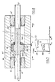
- Seals 26 prevent elastomer leaks between the ring 25 and the chamber of the cylinder 24.
- the two chambers 24a, 24b, separated in the cylinder 24 by the head 23 of the piston may, under certain conditions, communicate with each other by passages 28 formed in the piston head on the in part.
- the washer 29 is not an elastic washer in the sense that it is understood usually made of thick steel relatively large, as will be indicated more specifically below.
- the washer will be plated against the front face of the piston 23 closing in this case the holes 28.
- the implementation is such that the device will somehow work by all or nothing, damping very little effort if the washer is not plated against the passages, and damping them considerably if the washer is pressed on the front face of the piston, the pressing the washer against the front face of the piston taking place almost instantly from the moment the effort, and more generally the speed, of load on the device increases by exceeding one predetermined threshold.
- the device somehow matches to a device of the prior art and which has been modified from in such a way that it practically comes into line that from a determined minimum threshold, below which it is almost inoperative, and beyond which it enters almost instantly when actuated at its level predetermined operation.
- Such a device can in particular be used on safety devices that need to come into action when shocks of intensity greater than a certain threshold appear.
- the applications are numerous, in particular in rail transport, for engineering structures, for shock absorption of machines or machines very heavy, to achieve earthquake protection of buildings, for bridge spans, etc.
- FIG 5 there is illustrated a particular application to the stability of a structure such than a railway bridge made up of several sleepers mounted end to end and resting on piles.
- aprons which are usually metallic, to expand freely according to temperature variations to which they may be subject.
- the aprons rest on the pile 33 by means of supports, such as the supports shown diagrammatically in 35 and 36.
- An interval 37 separates the two aprons from so as to allow the required expansion play.
- the problem is that, for example, if a convoy of railway engaged on the bridge must brake suddenly, the kinetic energy of braking returned on the track may cause the batteries of the bridge which are going to be subjected to the training effort which is transmitted to them by the apron.
- the problem is resolved by placing, between the adjacent deck members, coupling devices 38 constituted by shock absorber devices according to the invention and for example of the type illustrated in FIGS. 3 and 4.
- the deck elements can therefore expand freely according to the temperature conditions prevailing on the bridge, the expansion efforts being very significant, but the travel speeds extremely reduced by example less than 1 mm / min.
- the apron by reaction will be trained at a certain speed, for example greater than 3 mm / min which will be sufficient to operate during closing almost instantaneously the washer 29 of the device associated coupler.
- the bridge deck reacts to such solicitation as if it were made in one piece unique going to the bridge abutments.
- the braking force will be distributed in cascade from pile to pile so as to distribute it on a sufficient number of batteries to absorb the effort.
- the threshold indicated by the valve closing operation device may be more important than that indicated, for example 30 mm / min, or even 300 mm / min.
- the operating characteristics of the device will be chosen in correspondence.
- Washer 49 is full and leaves some passage clearance 51 behind it with passages 48, while the washer 50 is perforated as seen in 52.
- the washer 49 will come to be pressed against the front face of the piston 43 closing the passages 48.
- the elastomer tends to pass from the chamber 44a to chamber 44b essentially through passages 52 and the annular passage 47; we find us substantially in the operating situation of a damping device of the prior art as illustrated in FIG. 1.
- the modification of system operation is performed brutally, the device passing from a minimum effort threshold to a second threshold determined.
- the washer 50 will also flex, and passages 52 will be closed (by application against the washer 49).
- the device will therefore operate with two closing levels following a level of no intervention.
- two such slats mounted in crosses could close the first two orifices 48 arranged in opposition, and the second two other orifices 48 also arranged diametrically in opposition (for balancing reasons), the two lamellae having different flexibilities, for example taking one a steel thickness of 2 mm and for the other, one steel thickness of 3.5 mm.
- Such a device operating with two closing levels following a level of no intervention will allow free expansion of the system for low speed, damping with a determined effort for a second speed threshold, and a quasi blocking for a third upper speed threshold.
- the device in question was of the threshold illustrated in figure 3.
- a washer metallic 29 steel type 35 NCD 16 (nickel chrome, molybdenum) 5 mm thick with an axial clearance between washers and piston of 2 mm, the bore diameter of the cylinder chamber 24 was 103 mm and the diameter of the piston head 23 was 100 mm thus leaving a play annular 27 of 1.5 mm for rolling the rubber during operation of the device.
- the head of the piston 23 was perforated by three passages 28 regularly distributed (therefore at 120 ° C. each others) around the piston, the diameter of each passage 28 being 24 mm and the center of each passage being located 80 mm from the central axis x'x of the device. The finally the diameter of the piston rod 22 was 42 mm.
- An application of the device to this case of figure could be that of wagon wagons railway.
- the reaction of the device is illustrated by the curve C2.
- the force applied by the elastomer caused the washer 29 closing the passages 28, the elastomer does not can pass more than through the ring clearance left between the chamber and the periphery of the piston 23.
- Figure 7 shows clearly the advantage of the device of the invention which allows practically from the start of the run to operate the device under the maximum collection effort desired, which increases the efficiency of the device.
- the piston 62 passes through the two ends of the chamber 64 in rings 65, 65 'screwed to each end of the cylinder 64, the seals 66, 66 'preventing elastomer leakage to the outside.
- Each piston 63 has a number of axial passages 68, for example three in number, distributed at 120 ° around the x'x axis of the device.
- the washer 71 is held in place on the piston head by means of a nut 72 screwed on a part corresponding threaded rod 62 of the piston.
- the device is to be double acting, that is to say in both directions, provision is advantageously made symmetrical mounting around the head 63 of the piston with a washer 71 'and a nut 72' as shown in lines dotted.
- the nut 72 (72 ') forms a shield for the washer 71 (71 ') when the system is actuated.
- the washers 71, 71 ' are not practically not deformed, that the device moves in the direction F or in the opposite direction F '.
- the pressure of the elastomer on the washers depending on the direction of movement (washer 71 if the piston moves in the direction F, or the washer 71 'if the piston moves in direction F') deforms the washer and the plate against the passages 68.
- the two curves C1 and C2 correspond to reaction forces F of the shock absorber for the speeds respective operating V1 and V2, and this depending of the passing clearance left to the eraser.
- the curve T in dashed lines indicates the curve obtained with the device which results in a reduction of play under the deflection of the washer 29.
- the two points t1 and t2 of the curve T correspond to the device clearance values for operating speeds V1 and V2.
- the washer 29 of Figure 3 has not sagged; the play is maximum, and the reaction force of the device is minimal; everything is passes substantially as if no device depreciation was present.
- the reaction force of the device takes place at level F1.
- the device will be able to act with a damping force not harmful to personnel or goods transported, up to a certain threshold of speed, and with a higher damping force in serious accident so as to reduce as much as do can damage it.
- the device used will generally be a single threshold, for example of the type illustrated in FIGS. 3, 4 and 8, allowing free expansion and free movement for very low speeds (generally for absorb thermal expansion play) and providing on the other hand, for a higher speed, exceeding a threshold determined, a collection at the maximum threshold which may correspond to a quasi blocking.
- a piston rod 82 of the device (which has been shown here as a through device, like that of FIG. 8), is equipped on the front face of the device (assuming F indicates the meaning of displacement of the piston in the cylinder) of a washer deformable 85, in front of passages 88 crossing the piston head.
- the ring game formed was referenced between the cylinder chamber 84 and the piston head ensuring the rolling of the rubber as in the device previously described.
- the washer 85 is pressed against the front face of the piston head 83, for example by means of a nut 89 further forming a shield for adapting the device at a determined tripping speed and improving all-or-nothing operation of the closing of the washer 85, as explained previously.
- the angle is actually used to have a good support for ensure that the washer stays in place.
- the washer as well shaped and supported by the nut 29 forming the shield reacts almost instantly in flexion, so that the device passes almost without transition from a position in which it allows free expansion of the system at a position in which it applies a force maximum reaction.
- the nut 89 forming the shield can advantageously be shaped with a groove such as illustrated 89a which reduces the response time by actuation of the device by promoting from the start of the deflection of the washer the establishment of the overpressure of the elastomer under the shield.
- Such a device could react for example by allowing the deformation to take place substantially freely when the speed does not exceed a determined threshold, and by providing a considerable effort on the contrary, without significant displacement of the piston in its cylinder, from that the speed will exceed the threshold value which can be chosen at will, for example in a range going from 3 mm / min (very low speed) to 300 mm / min (speed somewhat larger), depending on the applications.
- reaction forces of the device of the order of 1,750 kN for a speed actuation value greater than 3 mm / min with a very limited displacement of the order of 1 to 3 mm the same device for a movement speed of around 1 mm / min letting the device move freely for example over a stroke of 100 mm with a maximum reaction force not exceeding 30 kN.
- the almost linear curve S1 illustrates the reaction force of a damping device such as example as the one illustrated in figure 8 but which would be devoid of the washer forming a shutter valve referenced 71.
- the operating curve becomes the S3 curve shown broken line.
- curve S3 practically follows the S1 curve at the start, and when the loading speed reaches 3 mm / min, the curve deforms and catches up mounted almost vertically parallel to the axis ordinates, curve S2.
- the system therefore reacts initially for low speeds as if the passages 68 through the head of the piston were free, reacting on the other hand brutally and working by letting the elastomer pass only through the annular passage between piston and cylinder as soon as the speed reaches or exceeds 3 mm / min.
- such a device can react for example by letting the deformation take place substantially free when the speed does not exceed a determined threshold, and on the contrary providing a considerable effort, corresponding to a quasi blocking and almost immediately as soon as the speed exceeds one threshold speed which can be chosen arbitrarily as weak as desired.
- the means of modifying the cross section were deformable mechanical resistant means such as reactive steel washers or lamellae directly, depending on their configuration, depending on deformation and / or displacement efforts which their were applied directly by the elastomer.
- means forming a shield allowed to adapt the effort to the washer or lamella and to increase this effort from the start of deformation of the means resistant in order to speed up the closing process of valves thus formed.
- these means could be valves controlled from the outside by detectors associated with the device and which would close the flaps partially or totally depending on the measures noted.
- the advantage of the device of the invention is that regardless of the size of the shock in question, the device can return to its original position and is not not destroyed by shock.
- the device can absorb non only the first seismic wave, but afterwards, its aftershocks.
- such strips will have the shaped like rectilinear or cruciform tabs.
- Devices can be piston crossing or not; the advantage of through devices is that they work both ways; the advantage of non-through devices is that the pressure of the elastomer automatically performs the recall function of the device after operation.
Landscapes
- Engineering & Computer Science (AREA)
- General Engineering & Computer Science (AREA)
- Architecture (AREA)
- Mechanical Engineering (AREA)
- Environmental & Geological Engineering (AREA)
- Emergency Management (AREA)
- Business, Economics & Management (AREA)
- Civil Engineering (AREA)
- Structural Engineering (AREA)
- Fluid-Damping Devices (AREA)
- Springs (AREA)
- Processing And Handling Of Plastics And Other Materials For Molding In General (AREA)
- Press Drives And Press Lines (AREA)
- Vibration Prevention Devices (AREA)
- Polyurethanes Or Polyureas (AREA)
- Solid-Sorbent Or Filter-Aiding Compositions (AREA)
- Vibration Dampers (AREA)
Description
- de la nature de l'élastomère utilisé (et notamment de sa viscosité plus ou moins importante),
- de l'importance du jeu laissé entre la tête du piston et le cylindre dans lequel il coulisse,
- de la longueur de la course de déplacement du piston,
- de la pression de compression initiale de remplissage de la chambre, etc.
Claims (10)
- Dispositif formant amortisseur de chocs et limiteur de mouvement du type utilisant au moins un piston qui se déplace dans un cylindre rempli d'une gomme élastomère sous pression élevée dont l'effet d'amortissement et éventuellement de rappel est essentiellement assuré par la compression de l'élastomère et son laminage dans des passages de sections réduites ménagés dans ledit dispositif pour permettre le passage de la gomme d'un côté à l'autre du piston lors du fonctionnement du dispositif, dispositif comportant en outre des moyens, tels notamment que des clapets qui, lorsqu'ils sont actionnés, réduisent ou laissent libre la section des passages susmentionnés, ledit dispositif étant caractérisé en ce que, au dessus d'un seuil de vitesse déterminé de déplacement du piston dans le cylindre, le dispositif réagit de façon quasi instantanée en délivrant la force maximale d'encaissement qu'il est susceptible de fournir, tandis que pour certaines au moins des valeurs inférieures à ce seuil, le dispositif n'oppose qu'une force minimale de réaction.
- Dispositif selon la revendication 1 caractérisé en ce qu'entre le seuil maximum et les valeurs de faible niveau d'actionnement, le dispositif présente un seuil intermédiaire de fonctionnement en "amortisseur" pour lequel la section des passages est réduite seulement partiellement par rapport à la réduction de cette section lors du fonctionnement du dispositif à son seuil maximum de fonctionnement.
- Dispositif selon la revendication 1 ou la revendication 2 caractérisé en ce que lesdits moyens de modification de la section de passages réagissent en fonction des efforts de déformation et/ou de déplacement appliqués sur eux par l'élastomère.
- Dispositif selon l'une quelconque des revendications précédentes caractérisé en ce que lesdits moyens de modification de la section de passage sont disposés en regard de certains au moins desdits passages (28, 48, 68, 88) ménagés pour que la gomme puisse passer d'un côté à l'autre de la tête du piston (23, 43, 63, 83) lors du fonctionnement du dispositif).
- Dispositif selon l'une des revendications précédentes caractérisé en ce que la réduction des sections de passage est réalisée au moyen de rondelles ou lamelles élastiques déformables par exemple en acier de plusieurs millimètres d'épaisseur (29, 49, 50, 71, 85).
- Dispositif selon la revendication 5 caractérisé en ce que, en avant desdites rondelles ou lamelles, est monté un moyen formant bouclier (72, 89), limitant l'action de l'élastomère sur la rondelle au début de sa déformation sur une partie seulement de sa surface, l'élastomère agissant ensuite sur la surface dégagée de la rondelle après fléchissement de celle-ci.
- Dispositif selon l'une des revendications précédentes caractérisé en ce qu'à partir d'un accroissement d'effort donné, la diminution de la section de passage est limitée, ainsi qu'en correspondance, l'effort encaissé qui est limité à une valeur maximale.
- Dispositif selon l'une quelconque des revendications précédentes caractérisé en ce qu'après encaissement d'un effort au seuil maximum, il comporte des passages complémentaires agissant en fin de l'action exercée réduisant cet effort.
- Dispositif selon l'une quelconque des revendications précédentes caractérisé en ce que plusieurs moyens de modification de la section de passage, tels que rondelles ou lamelles formant clapets obturant simultanément ou successivement pour des seuils différents d'effort un ou plusieurs passage(s), sont montés en série ou en parallèle pour déformer à volonté la courbe de fonctionnement du dispositif.
- Application d'un dispositif selon l'une quelconque des revendications 1 à 8, à la stabilité d'un ouvrage tel qu'un pont de chemin de fer constitué de plusieurs traverses montées bout à bout et reposant sur des piles, caractérisée en ce que les divers tabliers (31, 32) sont réunis entre eux et/ou aux piles (33) par des dispositifs (38) du type précité, dans lesquels lesdits moyens de modification de la section de passage (29) sont ouverts à l'état de repos du pont et obturent lesdits passages (28) dès qu'est dépassé un seuil de vitesse déterminé de déplacement du piston dans son cylindre.
Applications Claiming Priority (3)
| Application Number | Priority Date | Filing Date | Title |
|---|---|---|---|
| FR9413618A FR2726874B1 (fr) | 1994-11-14 | 1994-11-14 | Dispositif amortisseur du type a compression hydrostatique d'elastomere et ses applications |
| FR9413618 | 1994-11-14 | ||
| PCT/FR1995/001475 WO1996015389A1 (fr) | 1994-11-14 | 1995-11-08 | Dispositif amortisseur du type a compression hydrostatique d'elastomere et ses applications |
Publications (2)
| Publication Number | Publication Date |
|---|---|
| EP0792423A1 EP0792423A1 (fr) | 1997-09-03 |
| EP0792423B1 true EP0792423B1 (fr) | 1999-03-03 |
Family
ID=9468777
Family Applications (1)
| Application Number | Title | Priority Date | Filing Date |
|---|---|---|---|
| EP95940291A Expired - Lifetime EP0792423B1 (fr) | 1994-11-14 | 1995-11-08 | Dispositif amortisseur du type a compression hydrostatique d'elastomere et ses applications |
Country Status (10)
| Country | Link |
|---|---|
| US (1) | US5829556A (fr) |
| EP (1) | EP0792423B1 (fr) |
| JP (1) | JP4130698B2 (fr) |
| AT (1) | ATE177172T1 (fr) |
| CA (1) | CA2202766A1 (fr) |
| DE (1) | DE69508106T2 (fr) |
| FR (1) | FR2726874B1 (fr) |
| GR (1) | GR3029588T3 (fr) |
| PL (1) | PL320113A1 (fr) |
| WO (1) | WO1996015389A1 (fr) |
Families Citing this family (25)
| Publication number | Priority date | Publication date | Assignee | Title |
|---|---|---|---|---|
| DE19819712A1 (de) * | 1998-05-02 | 1999-11-11 | Daimler Chrysler Ag | Stellzylinder für eine Lenkungsanordnung eines Kraftfahrzeugs |
| US6364078B1 (en) * | 1998-08-27 | 2002-04-02 | Bose Corporation | Wheel damping |
| DE10161972B4 (de) * | 2001-12-17 | 2010-09-09 | Maurer Söhne Gmbh & Co. Kg | Energieabsorptionsvorrichtung |
| DE10204590B4 (de) * | 2002-02-05 | 2004-05-13 | Thyssenkrupp Bilstein Gmbh | Federbein |
| NL1031880C2 (nl) * | 2006-05-24 | 2007-11-30 | Koni Bv | Eenwegklep voor een schokdemper. |
| JP2008151294A (ja) * | 2006-12-19 | 2008-07-03 | Railway Technical Res Inst | 緩衝用のシリンダ装置 |
| DE102008001097A1 (de) * | 2008-04-09 | 2009-10-22 | Zf Friedrichshafen Ag | Elastisches Verbindungselement mit veränderlicher Steifigkeit |
| US9249558B2 (en) | 2009-09-15 | 2016-02-02 | Robert S. Bierwith | Hydraulic locking mechanism for securing teeth and tooth carrying adapters to excavating buckets of excavating equipment |
| CN102606665A (zh) * | 2012-03-27 | 2012-07-25 | 北京工业大学 | 高耗能间隙被动调节粘滞阻尼器 |
| JP5803008B2 (ja) * | 2012-06-21 | 2015-11-04 | Smc株式会社 | 両ロッド型ショックアブソーバ |
| DE102012106626B3 (de) | 2012-07-20 | 2013-09-26 | Krauss-Maffei Wegmann Gmbh & Co. Kg | Waffenplattform, militärisches Fahrzeug mit einer Waffenplattform und Verfahren zum Betrieb einer Waffenplattform |
| US9187881B2 (en) | 2013-09-20 | 2015-11-17 | Berkeley Forge & Tool, Inc. | Reliable connection system and assemblies and methods for using the reliable connections |
| EP3077605A4 (fr) * | 2013-12-02 | 2017-08-23 | The Governing Council of the University of Toronto | Système pour atténuer les effets d'un événement sismique |
| CN107002810B (zh) * | 2014-11-25 | 2019-06-07 | Kyb株式会社 | 阻尼阀和缓冲器 |
| JP6442248B2 (ja) * | 2014-11-25 | 2018-12-19 | Kyb株式会社 | 減衰バルブ及び緩衝器 |
| JP6514492B2 (ja) * | 2014-11-25 | 2019-05-15 | Kyb株式会社 | 減衰バルブ及び緩衝器 |
| DE102016212654A1 (de) * | 2016-07-12 | 2018-01-18 | Stabilus Gmbh | Gleisbremsdämpfer |
| CN106197979B (zh) * | 2016-07-28 | 2019-04-16 | 煤炭科学技术研究院有限公司 | 一种压力自缓冲的大流量安全阀试验装置 |
| US9890828B1 (en) * | 2016-10-28 | 2018-02-13 | Teraflex, Inc. | Through-shaft steering damper |
| RU2661562C1 (ru) * | 2017-01-27 | 2018-07-17 | Общество с ограниченной ответственностью Научно-производственная фирма "МКТ-АСДМ" | Обратный клапан |
| CN110777640A (zh) * | 2019-11-07 | 2020-02-11 | 湘潭大学 | 一种悬浮腔体结构高耗能桥梁抗震挡块 |
| CN111851281B (zh) * | 2020-08-04 | 2022-06-10 | 江苏景然生态建设集团有限公司 | 一种用于钢-混组合桥梁的防共振装置的工作方法 |
| DE102020130252A1 (de) | 2020-11-17 | 2021-11-18 | Audi Aktiengesellschaft | Sicherungsvorrichtung zum Abbremsen einer Relativgeschwindigkeit zweier Bauteile zueinander sowie Kraftfahrzeug mit einer solchen Sicherungsvorrichtung |
| CN113294404B (zh) * | 2021-04-20 | 2022-11-11 | 上海机电工程研究所 | 橡胶与胶泥共用的动量及能量吸收装置 |
| US12679530B2 (en) * | 2022-10-26 | 2026-07-14 | Safran Landing Systems Canada Inc. | Landing gear main fitting with integral shock absorber |
Family Cites Families (19)
| Publication number | Priority date | Publication date | Assignee | Title |
|---|---|---|---|---|
| US3053526A (en) * | 1958-12-31 | 1962-09-11 | Menasco Mfg Company | Dampers and damped springs |
| GB1033810A (en) * | 1963-07-15 | 1966-06-22 | Woodhead Monroe Ltd | Improvements relating to vibration dampers |
| US3368697A (en) * | 1966-03-22 | 1968-02-13 | Miner Inc W H | Cushioning device |
| GB1137219A (en) * | 1967-07-31 | 1968-12-18 | Alinari Carlo | Valve piston device |
| US3831626A (en) * | 1972-12-14 | 1974-08-27 | Peddinghaus Carl Ullrich Dr | Piston for a shock absorber |
| US3819060A (en) * | 1973-08-17 | 1974-06-25 | Menasco Mfg Co | Damping apparatus |
| JPS5131377A (ja) * | 1974-09-10 | 1976-03-17 | Yokohama Rubber Co Ltd | Kanshotai |
| PL122000B1 (en) * | 1979-11-08 | 1982-06-30 | Polskie Koleje Panstwowe Centralny Osrodek Badan I Rozwoju Techniki Kolejnictwa | Elastomeric shock absorber |
| JPS6123943Y2 (fr) * | 1980-12-26 | 1986-07-18 | ||
| US4867286A (en) * | 1984-01-25 | 1989-09-19 | Tayco Developments, Inc. | Shock absorber having fluid amplified piston head with relief valve which provides second stage of fluid amplification |
| DE3508574A1 (de) * | 1985-03-11 | 1986-09-18 | Karlheinz 5800 Hagen Menkhoff | Elastomer federsystem mit ventilgesteuerter federkennlinie |
| JPS61165037A (ja) * | 1985-12-27 | 1986-07-25 | Sanwa Tekki Corp | 微振動防振装置 |
| US5277283A (en) * | 1988-09-19 | 1994-01-11 | Atsugi Unisia Corporation | Variable damping-characteristics shock absorber with adjustable orifice construction variable of fluid flow restriction depending upon fluid pressure difference |
| JPH0547310Y2 (fr) * | 1988-09-29 | 1993-12-13 | ||
| DE3842158A1 (de) * | 1988-12-15 | 1990-06-21 | Karlheinz Menkhoff | Elastomer spannpaket mit ventilkolben |
| US5265392A (en) * | 1989-07-05 | 1993-11-30 | Tesit S.P.A. | Aseismatic support for constructions subject to high thermal deformations |
| US5207300A (en) * | 1990-06-29 | 1993-05-04 | Boge Aktiengesellschaft | Hydraulic, adjustable vibration damper for motor vehicles |
| JPH04101831U (ja) * | 1991-02-13 | 1992-09-02 | 株式会社昭和製作所 | 油圧緩衝器のバルブ構造 |
| PL170036B1 (pl) * | 1993-04-28 | 1996-10-31 | Urzadzen Mechanicznych Kamax S | Amortyzator elastomerowy PL |
-
1994
- 1994-11-14 FR FR9413618A patent/FR2726874B1/fr not_active Expired - Fee Related
-
1995
- 1995-11-08 DE DE69508106T patent/DE69508106T2/de not_active Expired - Fee Related
- 1995-11-08 US US08/809,623 patent/US5829556A/en not_active Expired - Lifetime
- 1995-11-08 EP EP95940291A patent/EP0792423B1/fr not_active Expired - Lifetime
- 1995-11-08 WO PCT/FR1995/001475 patent/WO1996015389A1/fr not_active Ceased
- 1995-11-08 CA CA002202766A patent/CA2202766A1/fr not_active Abandoned
- 1995-11-08 PL PL95320113A patent/PL320113A1/xx unknown
- 1995-11-08 JP JP51578796A patent/JP4130698B2/ja not_active Expired - Lifetime
- 1995-11-08 AT AT95940291T patent/ATE177172T1/de not_active IP Right Cessation
-
1999
- 1999-03-05 GR GR990400675T patent/GR3029588T3/el unknown
Also Published As
| Publication number | Publication date |
|---|---|
| FR2726874B1 (fr) | 1996-12-20 |
| FR2726874A1 (fr) | 1996-05-15 |
| US5829556A (en) | 1998-11-03 |
| ATE177172T1 (de) | 1999-03-15 |
| DE69508106T2 (de) | 1999-08-12 |
| CA2202766A1 (fr) | 1996-05-23 |
| WO1996015389A1 (fr) | 1996-05-23 |
| JP4130698B2 (ja) | 2008-08-06 |
| GR3029588T3 (en) | 1999-06-30 |
| PL320113A1 (en) | 1997-09-15 |
| JPH10512942A (ja) | 1998-12-08 |
| DE69508106D1 (de) | 1999-04-08 |
| EP0792423A1 (fr) | 1997-09-03 |
Similar Documents
| Publication | Publication Date | Title |
|---|---|---|
| EP0792423A1 (fr) | Dispositif amortisseur du type a compression hydrostatique d'elastomere et ses applications | |
| EP0666967B1 (fr) | Dispositif amortisseur pour systeme mecanique | |
| EP0446338B1 (fr) | Procede de suspension de roue de vehicule | |
| FR2625277A1 (fr) | Amortisseur hydraulique | |
| FR2481771A1 (fr) | Agencement de montage d'un moteur dans un vehicule | |
| EP2417376B1 (fr) | Dispositif a glissement avec friction controlee, tel qu'un amortisseur, pouvant fonctionner dans les deux sens | |
| EP0873457A1 (fr) | Dispositif d'amortissement pour des elements d'une structure de genie civil | |
| EP0479647A1 (fr) | Galet tendeur fonctionnant par cisaillement autour d'un centre de rotation fictif et présentant une double rigidité par l'intervention d'une butée | |
| EP0360350A1 (fr) | Palier à film fluide et son procédé de réalisation | |
| FR2805872A1 (fr) | Clapet de laminage a raideur reglable et amortisseur associe | |
| EP0363271B1 (fr) | Ressort de compression monobloc | |
| CA2261360A1 (fr) | Dispositif mecanique a deplacement bimodal | |
| FR2540206A1 (fr) | Amortisseur hydraulique | |
| FR2777614A1 (fr) | Amortisseur de chocs du type a compression de fluide elastomere presentant au moins deux plages differentes de fonctionnement | |
| FR2821654A1 (fr) | Amortisseur ou limiteur d'efforts en particulier pour ouvrages de genie civil | |
| FR2463328A3 (fr) | Amortisseur de chocs pour dispositifs d'accrochage automatique de wagons de chemin de fer | |
| EP1431600A1 (fr) | Palier à roulement muni d'un "squeeze film" pour l'absorption de charge en cas de perte d'aube | |
| EP2917605B1 (fr) | Piston d'amortisseur et amortisseur le comportant | |
| BE500265A (fr) | ||
| EP3816474B1 (fr) | Dispositif de dissipation hydraulique pour ouvrage d'art | |
| EP0693995A1 (fr) | Dispositif de transmission d'energie de commande mecanique | |
| EP1171724A1 (fr) | Dispositif formant amortisseur dissymetrique pour une suspension de vehicule automobile | |
| CH642166A5 (fr) | Amortisseur de recul d'une arme automatique a tir rapide. | |
| FR2860851A1 (fr) | Butee de compresion, notamment pour amortisseur de suspension de vehicule automobile | |
| FR2811389A1 (fr) | Frein a disque perfectionne a rappel et rattrapage d'usure de plaquette par deformation elastique et plastique, et procede |
Legal Events
| Date | Code | Title | Description |
|---|---|---|---|
| PUAI | Public reference made under article 153(3) epc to a published international application that has entered the european phase |
Free format text: ORIGINAL CODE: 0009012 |
|
| 17P | Request for examination filed |
Effective date: 19970325 |
|
| AK | Designated contracting states |
Kind code of ref document: A1 Designated state(s): AT DE FR GB GR IT PT |
|
| GRAG | Despatch of communication of intention to grant |
Free format text: ORIGINAL CODE: EPIDOS AGRA |
|
| 17Q | First examination report despatched |
Effective date: 19980518 |
|
| GRAG | Despatch of communication of intention to grant |
Free format text: ORIGINAL CODE: EPIDOS AGRA |
|
| GRAG | Despatch of communication of intention to grant |
Free format text: ORIGINAL CODE: EPIDOS AGRA |
|
| GRAH | Despatch of communication of intention to grant a patent |
Free format text: ORIGINAL CODE: EPIDOS IGRA |
|
| GRAH | Despatch of communication of intention to grant a patent |
Free format text: ORIGINAL CODE: EPIDOS IGRA |
|
| GRAA | (expected) grant |
Free format text: ORIGINAL CODE: 0009210 |
|
| AK | Designated contracting states |
Kind code of ref document: B1 Designated state(s): AT DE FR GB GR IT PT |
|
| REF | Corresponds to: |
Ref document number: 177172 Country of ref document: AT Date of ref document: 19990315 Kind code of ref document: T |
|
| GBT | Gb: translation of ep patent filed (gb section 77(6)(a)/1977) |
Effective date: 19990303 |
|
| REF | Corresponds to: |
Ref document number: 69508106 Country of ref document: DE Date of ref document: 19990408 |
|
| REG | Reference to a national code |
Ref country code: PT Ref legal event code: SC4A Free format text: AVAILABILITY OF NATIONAL TRANSLATION Effective date: 19990312 |
|
| PGFP | Annual fee paid to national office [announced via postgrant information from national office to epo] |
Ref country code: AT Payment date: 19991102 Year of fee payment: 5 |
|
| PGFP | Annual fee paid to national office [announced via postgrant information from national office to epo] |
Ref country code: PT Payment date: 19991109 Year of fee payment: 5 |
|
| PLBE | No opposition filed within time limit |
Free format text: ORIGINAL CODE: 0009261 |
|
| STAA | Information on the status of an ep patent application or granted ep patent |
Free format text: STATUS: NO OPPOSITION FILED WITHIN TIME LIMIT |
|
| 26N | No opposition filed | ||
| PG25 | Lapsed in a contracting state [announced via postgrant information from national office to epo] |
Ref country code: AT Free format text: LAPSE BECAUSE OF NON-PAYMENT OF DUE FEES Effective date: 20001108 |
|
| PG25 | Lapsed in a contracting state [announced via postgrant information from national office to epo] |
Ref country code: PT Free format text: LAPSE BECAUSE OF NON-PAYMENT OF DUE FEES Effective date: 20010531 |
|
| REG | Reference to a national code |
Ref country code: PT Ref legal event code: MM4A Free format text: LAPSE DUE TO NON-PAYMENT OF FEES Effective date: 20010531 |
|
| PGFP | Annual fee paid to national office [announced via postgrant information from national office to epo] |
Ref country code: GR Payment date: 20011129 Year of fee payment: 7 |
|
| REG | Reference to a national code |
Ref country code: GB Ref legal event code: IF02 |
|
| PGFP | Annual fee paid to national office [announced via postgrant information from national office to epo] |
Ref country code: DE Payment date: 20021114 Year of fee payment: 8 |
|
| PG25 | Lapsed in a contracting state [announced via postgrant information from national office to epo] |
Ref country code: GR Free format text: LAPSE BECAUSE OF NON-PAYMENT OF DUE FEES Effective date: 20030609 |
|
| PGFP | Annual fee paid to national office [announced via postgrant information from national office to epo] |
Ref country code: GB Payment date: 20031105 Year of fee payment: 9 |
|
| PG25 | Lapsed in a contracting state [announced via postgrant information from national office to epo] |
Ref country code: DE Free format text: LAPSE BECAUSE OF NON-PAYMENT OF DUE FEES Effective date: 20040602 |
|
| PG25 | Lapsed in a contracting state [announced via postgrant information from national office to epo] |
Ref country code: GB Free format text: LAPSE BECAUSE OF NON-PAYMENT OF DUE FEES Effective date: 20041108 |
|
| GBPC | Gb: european patent ceased through non-payment of renewal fee |
Effective date: 20041108 |
|
| REG | Reference to a national code |
Ref country code: FR Ref legal event code: TP |
|
| PG25 | Lapsed in a contracting state [announced via postgrant information from national office to epo] |
Ref country code: IT Free format text: LAPSE BECAUSE OF NON-PAYMENT OF DUE FEES;WARNING: LAPSES OF ITALIAN PATENTS WITH EFFECTIVE DATE BEFORE 2007 MAY HAVE OCCURRED AT ANY TIME BEFORE 2007. THE CORRECT EFFECTIVE DATE MAY BE DIFFERENT FROM THE ONE RECORDED. Effective date: 20051108 |
|
| PGFP | Annual fee paid to national office [announced via postgrant information from national office to epo] |
Ref country code: FR Payment date: 20100819 Year of fee payment: 16 |
|
| REG | Reference to a national code |
Ref country code: FR Ref legal event code: ST Effective date: 20120731 |
|
| PG25 | Lapsed in a contracting state [announced via postgrant information from national office to epo] |
Ref country code: FR Free format text: LAPSE BECAUSE OF NON-PAYMENT OF DUE FEES Effective date: 20111130 |