EP0792618B1 - Bildaufnahmesystem zur Erfassung von krankem Gewebe mit nativer Fluoreszenz in Verdauungs- und Atemwegen - Google Patents
Bildaufnahmesystem zur Erfassung von krankem Gewebe mit nativer Fluoreszenz in Verdauungs- und Atemwegen Download PDFInfo
- Publication number
- EP0792618B1 EP0792618B1 EP97300654A EP97300654A EP0792618B1 EP 0792618 B1 EP0792618 B1 EP 0792618B1 EP 97300654 A EP97300654 A EP 97300654A EP 97300654 A EP97300654 A EP 97300654A EP 0792618 B1 EP0792618 B1 EP 0792618B1
- Authority
- EP
- European Patent Office
- Prior art keywords
- light
- autofluorescence
- tissue
- excitation light
- color
- Prior art date
- Legal status (The legal status is an assumption and is not a legal conclusion. Google has not performed a legal analysis and makes no representation as to the accuracy of the status listed.)
- Expired - Lifetime
Links
- 238000003384 imaging method Methods 0.000 title claims description 20
- 210000001035 gastrointestinal tract Anatomy 0.000 title description 3
- 210000002345 respiratory system Anatomy 0.000 title description 3
- 230000002496 gastric effect Effects 0.000 title 1
- 230000005284 excitation Effects 0.000 claims description 46
- 230000003595 spectral effect Effects 0.000 claims description 26
- 230000002159 abnormal effect Effects 0.000 claims description 15
- QSHDDOUJBYECFT-UHFFFAOYSA-N mercury Chemical compound [Hg] QSHDDOUJBYECFT-UHFFFAOYSA-N 0.000 claims description 6
- 229910052753 mercury Inorganic materials 0.000 claims description 6
- 230000001419 dependent effect Effects 0.000 claims description 3
- 238000001530 Raman microscopy Methods 0.000 claims 2
- 230000003287 optical effect Effects 0.000 claims 2
- 206010028980 Neoplasm Diseases 0.000 description 27
- 201000011510 cancer Diseases 0.000 description 22
- 238000001514 detection method Methods 0.000 description 17
- 239000003814 drug Substances 0.000 description 12
- 229940079593 drug Drugs 0.000 description 12
- 238000010586 diagram Methods 0.000 description 11
- 238000012545 processing Methods 0.000 description 11
- 238000005286 illumination Methods 0.000 description 10
- 230000003902 lesion Effects 0.000 description 10
- 239000000835 fiber Substances 0.000 description 9
- 238000001228 spectrum Methods 0.000 description 9
- 210000000056 organ Anatomy 0.000 description 8
- 210000001072 colon Anatomy 0.000 description 7
- 239000000523 sample Substances 0.000 description 7
- 239000003086 colorant Substances 0.000 description 6
- 238000000799 fluorescence microscopy Methods 0.000 description 6
- 230000004044 response Effects 0.000 description 6
- 238000004364 calculation method Methods 0.000 description 5
- 230000008859 change Effects 0.000 description 5
- 238000005259 measurement Methods 0.000 description 4
- 238000000034 method Methods 0.000 description 4
- 241000282412 Homo Species 0.000 description 3
- 238000001574 biopsy Methods 0.000 description 3
- 230000000694 effects Effects 0.000 description 3
- 238000012216 screening Methods 0.000 description 3
- 210000002784 stomach Anatomy 0.000 description 3
- 208000009458 Carcinoma in Situ Diseases 0.000 description 2
- 230000008901 benefit Effects 0.000 description 2
- 230000007423 decrease Effects 0.000 description 2
- 230000003247 decreasing effect Effects 0.000 description 2
- 238000011161 development Methods 0.000 description 2
- 230000002708 enhancing effect Effects 0.000 description 2
- 230000006872 improvement Effects 0.000 description 2
- 201000004933 in situ carcinoma Diseases 0.000 description 2
- 210000004072 lung Anatomy 0.000 description 2
- 230000003211 malignant effect Effects 0.000 description 2
- 238000004519 manufacturing process Methods 0.000 description 2
- 230000005855 radiation Effects 0.000 description 2
- 238000012360 testing method Methods 0.000 description 2
- OAICVXFJPJFONN-UHFFFAOYSA-N Phosphorus Chemical compound [P] OAICVXFJPJFONN-UHFFFAOYSA-N 0.000 description 1
- 238000004458 analytical method Methods 0.000 description 1
- 239000008280 blood Substances 0.000 description 1
- 210000004369 blood Anatomy 0.000 description 1
- 239000011248 coating agent Substances 0.000 description 1
- 238000000576 coating method Methods 0.000 description 1
- 238000012790 confirmation Methods 0.000 description 1
- 230000008878 coupling Effects 0.000 description 1
- 238000010168 coupling process Methods 0.000 description 1
- 238000005859 coupling reaction Methods 0.000 description 1
- 230000006378 damage Effects 0.000 description 1
- 238000013461 design Methods 0.000 description 1
- 210000003238 esophagus Anatomy 0.000 description 1
- 238000001914 filtration Methods 0.000 description 1
- 238000002073 fluorescence micrograph Methods 0.000 description 1
- 238000000338 in vitro Methods 0.000 description 1
- 238000001727 in vivo Methods 0.000 description 1
- 239000011159 matrix material Substances 0.000 description 1
- 238000002156 mixing Methods 0.000 description 1
- 238000010606 normalization Methods 0.000 description 1
- 230000007170 pathology Effects 0.000 description 1
- 230000008569 process Effects 0.000 description 1
- 210000000664 rectum Anatomy 0.000 description 1
- 230000000241 respiratory effect Effects 0.000 description 1
- 230000000717 retained effect Effects 0.000 description 1
- 238000004611 spectroscopical analysis Methods 0.000 description 1
- 230000003685 thermal hair damage Effects 0.000 description 1
- 238000002834 transmittance Methods 0.000 description 1
- 230000000007 visual effect Effects 0.000 description 1
Images



Classifications
-
- A—HUMAN NECESSITIES
- A61—MEDICAL OR VETERINARY SCIENCE; HYGIENE
- A61B—DIAGNOSIS; SURGERY; IDENTIFICATION
- A61B5/00—Measuring for diagnostic purposes; Identification of persons
- A61B5/42—Detecting, measuring or recording for evaluating the gastrointestinal, the endocrine or the exocrine systems
-
- A—HUMAN NECESSITIES
- A61—MEDICAL OR VETERINARY SCIENCE; HYGIENE
- A61B—DIAGNOSIS; SURGERY; IDENTIFICATION
- A61B1/00—Instruments for performing medical examinations of the interior of cavities or tubes of the body by visual or photographical inspection, e.g. endoscopes; Illuminating arrangements therefor
- A61B1/00002—Operational features of endoscopes
- A61B1/00004—Operational features of endoscopes characterised by electronic signal processing
- A61B1/00009—Operational features of endoscopes characterised by electronic signal processing of image signals during a use of endoscope
-
- A—HUMAN NECESSITIES
- A61—MEDICAL OR VETERINARY SCIENCE; HYGIENE
- A61B—DIAGNOSIS; SURGERY; IDENTIFICATION
- A61B1/00—Instruments for performing medical examinations of the interior of cavities or tubes of the body by visual or photographical inspection, e.g. endoscopes; Illuminating arrangements therefor
- A61B1/00163—Optical arrangements
- A61B1/00186—Optical arrangements with imaging filters
-
- A—HUMAN NECESSITIES
- A61—MEDICAL OR VETERINARY SCIENCE; HYGIENE
- A61B—DIAGNOSIS; SURGERY; IDENTIFICATION
- A61B1/00—Instruments for performing medical examinations of the interior of cavities or tubes of the body by visual or photographical inspection, e.g. endoscopes; Illuminating arrangements therefor
- A61B1/04—Instruments for performing medical examinations of the interior of cavities or tubes of the body by visual or photographical inspection, e.g. endoscopes; Illuminating arrangements therefor combined with photographic or television appliances
- A61B1/042—Instruments for performing medical examinations of the interior of cavities or tubes of the body by visual or photographical inspection, e.g. endoscopes; Illuminating arrangements therefor combined with photographic or television appliances characterised by a proximal camera, e.g. a CCD camera
-
- A—HUMAN NECESSITIES
- A61—MEDICAL OR VETERINARY SCIENCE; HYGIENE
- A61B—DIAGNOSIS; SURGERY; IDENTIFICATION
- A61B1/00—Instruments for performing medical examinations of the interior of cavities or tubes of the body by visual or photographical inspection, e.g. endoscopes; Illuminating arrangements therefor
- A61B1/04—Instruments for performing medical examinations of the interior of cavities or tubes of the body by visual or photographical inspection, e.g. endoscopes; Illuminating arrangements therefor combined with photographic or television appliances
- A61B1/043—Instruments for performing medical examinations of the interior of cavities or tubes of the body by visual or photographical inspection, e.g. endoscopes; Illuminating arrangements therefor combined with photographic or television appliances for fluorescence imaging
-
- A—HUMAN NECESSITIES
- A61—MEDICAL OR VETERINARY SCIENCE; HYGIENE
- A61B—DIAGNOSIS; SURGERY; IDENTIFICATION
- A61B1/00—Instruments for performing medical examinations of the interior of cavities or tubes of the body by visual or photographical inspection, e.g. endoscopes; Illuminating arrangements therefor
- A61B1/06—Instruments for performing medical examinations of the interior of cavities or tubes of the body by visual or photographical inspection, e.g. endoscopes; Illuminating arrangements therefor with illuminating arrangements
- A61B1/0646—Instruments for performing medical examinations of the interior of cavities or tubes of the body by visual or photographical inspection, e.g. endoscopes; Illuminating arrangements therefor with illuminating arrangements with illumination filters
-
- A—HUMAN NECESSITIES
- A61—MEDICAL OR VETERINARY SCIENCE; HYGIENE
- A61B—DIAGNOSIS; SURGERY; IDENTIFICATION
- A61B5/00—Measuring for diagnostic purposes; Identification of persons
- A61B5/0059—Measuring for diagnostic purposes; Identification of persons using light, e.g. diagnosis by transillumination, diascopy, fluorescence
- A61B5/0071—Measuring for diagnostic purposes; Identification of persons using light, e.g. diagnosis by transillumination, diascopy, fluorescence by measuring fluorescence emission
-
- A—HUMAN NECESSITIES
- A61—MEDICAL OR VETERINARY SCIENCE; HYGIENE
- A61B—DIAGNOSIS; SURGERY; IDENTIFICATION
- A61B5/00—Measuring for diagnostic purposes; Identification of persons
- A61B5/0059—Measuring for diagnostic purposes; Identification of persons using light, e.g. diagnosis by transillumination, diascopy, fluorescence
- A61B5/0082—Measuring for diagnostic purposes; Identification of persons using light, e.g. diagnosis by transillumination, diascopy, fluorescence adapted for particular medical purposes
- A61B5/0084—Measuring for diagnostic purposes; Identification of persons using light, e.g. diagnosis by transillumination, diascopy, fluorescence adapted for particular medical purposes for introduction into the body, e.g. by catheters
-
- A—HUMAN NECESSITIES
- A61—MEDICAL OR VETERINARY SCIENCE; HYGIENE
- A61B—DIAGNOSIS; SURGERY; IDENTIFICATION
- A61B5/00—Measuring for diagnostic purposes; Identification of persons
- A61B5/42—Detecting, measuring or recording for evaluating the gastrointestinal, the endocrine or the exocrine systems
- A61B5/4222—Evaluating particular parts, e.g. particular organs
- A61B5/4255—Intestines, colon or appendix
Definitions
- the present invention relates to cancer detection systems, and in particular to cancer detection systems that measure the native fluorescence response of normal, precancerous and cancerous tissue.
- fluorescence imaging This imaging mode provides different information than the conventionally used reflectance imaging mode.
- the physician inserts an endoscope or fiber optic bundle into the body cavity which conducts illumination into the cavity from a light source.
- the light source is typically white light whereas in fluorescence, a specific excitation wavelength(s) is used.
- the reflectance or fluorescence image is captured by the imaging fiber bundle of the endoscope and viewed by the physician through the ocular of the endoscope.
- a camera can be attached to the ocular so that the image can be displayed on a monitor.
- a physician typically prepares a patient by administering a photosensitive drug that binds to cancerous tissue.
- the photosensitive drugs cause the cancerous tissue to contrast with the surrounding tissue, thereby allowing the physician to visually detect the presence of cancer.
- the problem with the use of photosensitive drugs to detect cancer is that most drugs have significant side effects. The most serious side effect is that the patients become hyper sun sensitive while the drugs are active. Therefore, patients who receive these drugs must be kept in darkened rooms for several days after the administration of the drugs. This method of cancer detection is therefore not suited for screening applications where it is desired to test as many patients as possible in the least amount of time.
- Another cancer detection method based on fluorescence imaging that eliminates the need to administer photosensitive drugs is based on the fact that cancerous or precancerous tissue responds differently to applied light than does normal tissue.
- monochromatic light When monochromatic light is applied to living tissue, a portion of the absorbed light will be re-emitted at different wavelengths in a process termed autofluorescence (also referred to as native fluorescence).
- autofluorescence also referred to as native fluorescence.
- the intensity or number of autofluorescence photons released by the abnormal tissue in the green portion of the visible light spectrum differs relative to the intensity or number of photons released by healthy tissue. In the red region of the visible light spectrum, the number of photons released by the healthy and abnormal tissue are closer to being similar.
- Examples of prior art systems which utilize the difference in fluorescence and autofluorescence intensity to detect the presence of cancer cells include U. S. Patent No. 4,786,813 to Svanberg et al.; U.S. Patent No. 4,930,516 ('516) to Alfano et al.; U.S. Patent No. 5,042,494 ('494) to Alfano; U.K. Patent Application No. 2,203,831, by Zeng Kun; U.S. Patent No. 5,131,398 ('398) to Alfano et al.; and PCT Application No. WO 90/10219 by Andersson-Engles.
- the systems described in each of these patents generally fall into two categories in order to discriminate between cancerous and non-cancerous cells.
- the first category one utilizes single point, narrow band spectroscopy measurements to detect cancerous tissue, while the second utilizes broad band imaging systems.
- Examples of the systems in the first category are the Alfano patents, '516, '494 and '398, which describe single point measurement systems. These systems use a ratiometric comparison of the narrow band intensity of autofluorescence light produced by healthy and suspect tissue, as well as a detection of a change in spectral peaks (i.e., a shift towards the blue) to indicate the presence of cancerous cells.
- Examples of the second category are illustrated by the Svanberg et al. and Andersson-Engles patents, which disclose systems for producing images of diseased tissue.
- the fluorescence or autofluorescence light produced by the tissue is divided into four beams that are filtered with a broadband filter before being applied to an intensified CCD camera.
- the output of the intensified CCD camera is used to compute ratios of the intensity of the four broad spectral bands.
- the ratio calculations are then displayed, typically as pseudo colors, on a monitor so that a physician can visually detect the presence of cancerous lesions.
- the calculation of ratios or the requirement for image processing is not desirable in a medical diagnostic aid system because the physician loses information that is, in our experience, necessary for diagnostic judgment. Such information is only retained by presenting the physician with a view of the tissue directly and not a mathematical representation of the tissue.
- the present invention is directed to address the problems of prior art cancer imaging systems and to improve the systems disclosed in the '494 and '662 applications in order to facilitate the detection of cancerous or precancerous tissue in the respiratory and gastrointestinal tracts.
- the present invention is an imaging system for detecting the presence of cancerous or precancerous lesions in vivo.
- a light source produces (e.g. blue) excitation light that is directed into an illumination guide of a fiber optic endoscope in order to illuminate a portion of tissue to be examined.
- the endoscope returns some reflected excitation light as well as autofluorescence light produced by the tissue under examination.
- Light received from the endoscope, through the imaging fiber bundle, is divided into two beams by a beam splitter.
- the first beam comprises autofluorescence light in the green portion of the visible light spectrum as well as any reflected blue excitation light.
- the second beam comprises autofluorescence light in the red portion of the spectrum.
- Light in the two beams is filtered and applied to a pair of image intensified CCD cameras.
- Real time images (i.e., 30 frames/s), produced by the CCD cameras, are applied to the red, green and blue color inputs of a color video monitor. Still images can be captured from the real time images and stored by means of a frame grabber in a computer.
- the blue and green color inputs of the video monitor are connected to receive the images produced by the camera that detects green autofluorescence light, while the red color input, of the color video monitor is connected to receive the image produced by the camera that detects the red autofluorescence light.
- the video monitor produces a display whereby normal tissue appears as approximately cyan in color, while potentially cancerous tissue appears reddish in color. It turns out that the perceived colors on the monitor represent the ratio of the two acquisition channels. This is an important aspect of the present invention since the ratio is displayed without calculations or digital image processing but by simply mixing the three color channels.
- a further aspect of the invention is a pair of controls that allow a physician to adjust the brightness and color contrast of the video display image by adjusting the gain of the red and green intensified CCD cameras in a specific proportion to compensate for the changes in autofluorescence from patient to patient, from organ to organ, and from location to location.
- a mercury arc lamp is used to produce the blue excitation light at the strong atomic line of 436 nanometers.
- Light from the arc lamp is gathered by an elliptical mirror and filtered by a dichroic mirror and a bandpass filter before it is directed into the illumination guide of the endoscope.
- This filtered light source gives high illumination power and is inexpensive to manufacture and is relatively easy to maintain.
- the present invention is a system for detecting cancerous or precancerous tissues using autofluorescence images that does not require the use of tumor enhancing drugs or intensive image processing.
- FIGURE 1 is a graph showing the differences in autofluorescence light intensity for normal and cancerous or precancerous tissue in humans. As indicated above, when blue excitation light is shined on tissue, some of the light will be absorbed and reemitted as autofluorescence light. The autofluorescence light has an intensity and spectral shape that is indicative of whether the tissue is normal or diseased. A spectral curve 10 represents the response of normal, healthy tissue, while a spectral curve 20 represents the response of tissue that is cancerous or precancerous. As can be seen, there is a significant difference in the intensity of the two curves in a first green channel 30, while the differences between the healthy and abnormal tissue in a second red channel 40 is small.
- the magnitude of the curves 10 and 20 shown in FIGURE 1 not only vary with wavelength, but also with the distance between a probe and the tissue under examination as well as the intensity of the light source. Therefore, in a practical sense it is not possible to determine whether tissue is cancerous by simply detecting the magnitude of the autofluorescence light in the (first) green channel. However, the ratios of the autofluorescence light intensities taken at two different wavelengths remain constant despite variations in the distance of the fiber optic probe to the tissue and the angle of the probe to the tissue. This is true since the intensities of the (first) green and (second) red channel change proportionally for the same kind of tissue.
- the intensity of red autofluorescence light for normal tissue R n divided by the intensity of the green autofluorescence light for normal tissue G n remains substantially constant despite variations in the distance and angle of the tip of the endoscope to the tissue under consideration.
- the ratio of the intensity of the red autofluorescence light R cis (CIS for carcinoma in situ) divided by the intensity of the green autofluorescence light GCIS remains substantially constant despite variations in the position and orientation of the endoscope.
- the inventors For healthy tissue, the inventors have found that the ratio of the response of the red channel to the green channel is approximately 0:54 for colon tissue and 0.16 for lung tissue, while for carcinoma in situ, the ratio of the red to green channel is approximately 1.6 for colon tissue and 0.6 for lung tissue. These values are given as examples only and they are highly dependent on the system, i.e., the spectral response of the imaging system. However, by calculating or by representing the ratio of the red channel autofluorescence light and the green channel autofluorescence light, a determination can be made whether the tissue under consideration is healthy or potentially cancerous when interpreted along with the contextual information of the image.
- FIGURE 2 shows the range of wavelengths used by the present invention to determine whether tissue is potentially cancerous or precancerous.
- the (second) red channel 60 is limited to wavelengths longer than 630 nanometers, while the (first) green channel 50 comprises wavelengths extending from approximately 490 to 560 nanometers.
- the areas in the red band have been normalized so that, in this part of the spectrum, the ratio of the normal and cancerous tissue is one. This normalization still results in a significant difference in the green band. Therefore, the ratio or a representation of the ratio will discriminate between normal and cancerous tissue.
- the present invention allows a physician to determine whether the tissue under consideration is potentially cancerous or precancerous.
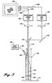
- the endoscope autofluorescence imaging system of the present invention includes an excitation light source 100 and a fiber optic endoscope 102, which may be a gastroscope, duodenoscope, choledochoscope, bronchoscope or colonoscope depending on the type of tissue to be examined.
- the endoscope may be an Olympus BF-20D for the respiratory tract, an Olympus GIF-XQ30 for the esophagus and stomach and an Olympus CF-30L for the rectum and colon.
- the light source 100 produces blue excitation light 104 which is fed through the incoherent illumination guide 106 of the fiber optic endoscope.
- the excitation light is focused by an outer lens 108 that is disposed at the distal end of the endoscope.
- the blue excitation light illuminates a portion of tissue 110 that is to be examined.
- the tissue is excited by the blue light and emits photons (autofluorescence light) 112 having a longer wavelength in the visible portion of the light spectrum.
- the autofluorescence light emitted by the. tissue along with some reflected blue excitation light is gathered by a lens 114 at the distal end of the endoscope and channeled through an imaging guide portion 116 of the endoscope through a number of conventional imaging lenses (not shown).
- autofluorescence light is applied to a dichroic mirror beam splitter 120.
- the beam splitter 120 has a cutoff wavelength between 565 and 575 nanometers.
- the beam splitter divides the autofluorescence light from the imaging guide into two spectral bands, namely a first, green band, and a second, red band.
- the autofluorescence light having wavelengths longer than the cutoff wavelength of the beam splitter 120 is directed toward a reflection mirror 122 that directs the autofluorescence light into a filter 124.
- the filter 124 is positioned in front of a red channel, image intensified CCD camera 126.
- Autofluorescence light having wavelengths less than the cutoff wavelength of the beam splitter 120 passes through the beam splitter toward a filter 128 that is positioned in front of a green channel image intensified CCD camera 130.
- the intensity of the red autofluorescence wavelength band that is applied to the camera 126 is substantially the same for normal tissue and abnormal tissue.
- the intensity of the green autofluorescence wavelength band applied to the camera 130 is substantially different for normal and abnormal tissue.
- the images produced by both CCD cameras 126 and 130 are combined on a color video monitor 150 that allows any abnormal tissue to be easily identified. Because a high power blue excitation light is employed and all the photons in the spectral bands are applied to the image intensified CCD cameras 126 and 130, the images produced by the cameras 126 and 130 are bright enough to distinguish between normal and abnormal tissue, even in the larger organs such as in the gastrointestinal tract, without the need for tumor enhancing photosensitive drugs.
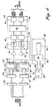
- FIGURE 4 is a more detailed block diagram of the imaging portion of the cancer detection system according to the present invention.
- the light is directed to the filters 124 and 128.
- the filter 124 is a long pass filter that blocks light having wavelengths less than 630 nanometers.
- the red autofluorescence light is directed onto the surface of a GEN II image intensifier 132 such as a DEP XX 1700 manufactured by Delft Instruments.
- the output of the image intensifier 132 is coupled through a fiber optic bundle 134 to the surface of a CCD image sensor 136 within the CCD camera 126.
- the green autofluorescence light passes through a bandpass filter 128 that removes any blue excitation light that may have been reflected off the surface of the tissue 110.
- the bandpass filter 128 removes light having wavelengths less than 490 nanometers or greater than 560 nanometers.
- the out of band attenuation of the filters 124 and 128 must be sufficient to ensure that virtually all of the reflected blue excitation light is blocked from reaching the CCD cameras.
- the green autofluorescence light is directed to a GEN II image intensifier 140.
- the output of the image intensifier 140 is coupled via a fiber optic bundle 142 to the surface of a CCD image sensor 144 within the green CCD camera 130.
- a genlock 149 within the camera 130 maintains the synchronization of the red CCD camera 126 to the green CCD camera 130.
- the analog output signals of the red and green image intensified CCD cameras 126 and 130 are fed to a pair of amplifiers 152, 154.
- the output of the amplifiers is fed into a video image processing board 155 that is part of a controlling computer 200.
- the controlling computer 200 includes an Intel 486/100MHz CPU 202 and 16 US of internal memory 204. However, other high speed digital computers could also be used.
- the video image processing board 155 includes a pair of analog-to-digital converters 156, 157, that receive the amplified video signals from the red and green CCD cameras, respectively.
- the analog-to-digital converters convert the analog video signals into a corresponding digital format.
- a pair of look up tables 158 and 160 are used to modify the relative gain of the digital video signals in a manner that will be described below. For each discrete value of the digital video signal, the CPU 202 reads up a corresponding digital value having the correct relative gain from the look up tables.
- the values of the digitized video signals read from the look up tables 158, 160, that are part of a random access memory 162 where they can be retrieved by the central processing unit for analysis at a later time.
- the digital video signals are continuously retrieved from the random access memory 162 and reconverted into an analog format by a pair of digital-to-analog converters 166 and 164.
- the two converters correspond respectively to the green and red channel images.
- the outputs of the digital to analog converters 164, 166 are applied directly to the red, green and blue inputs of the color monitor 150 shown in FIGURE 3. This means that the video signal from the green CCD camera 130 is coupled to a green input 150G of the color monitor as well as a blue input 150B.
- a red input 150R of the color monitor receives the video signal from the red CCD camera 126.
- the color video monitor 150 receives the video signals and produces a color image, whereby the healthy tissue is approximately cyan in color and any abnormal or potentially cancerous tissue appears reddish in color and is therefore easily identifiable by a trained physician.
- the direct coupling of the video signals from the video input/output board of cameras 126, 130 through the video image processing board 155 to the color video monitor 150 is accomplished without any significant digital signal processing other than a minor change in the gain as will be described below.
- This allows a physician to view as true a representation of the data from the intensified CCD cameras as possible. In other words, the structure (e.g., contrast and texture) of the image are maintained. Therefore, the physician is able to consider subtleties in the video image that may otherwise be removed or masked as a result of any digital image processing that takes place before the image is displayed.
- the two autofluorescence image signals produced by the CCD cameras are representative of the true autofluorescence image of the tissue in the respective wavelength bands, allowing lesions to be seen at video rates within their context. This aspect is essential for the physician to recognize potential lesions which he/she can then biopsy through the biopsy channel of the endoscope for pathology confirmation.
- the fluorescence imaging system of the present invention is unique in that it does not perform calculations to compensate for distance and angle effects of the endoscope with respect to the tissue under examination. Instead, the images from the red and green cameras are superimposed upon each other and displayed as distinct colors. This allows the physician to interpret the image using the visual experience they have acquired over their lifetime. In addition, the system circumvents the problem of an algorithm making a clinical decision as to what tissue may or may not be cancerous as well as allows the tissue to be observed in real time.
- the present invention provides a set of controls 220 that allow the physician to adjust the "brightness” and "color balance” of the color video image produced.
- the controls 220 can be realized by hardware or software control of the camera gain.
- the brightness of the displayed image is related to the gain of both the red and green channels while the color balance is related to the relative gain of the green and red channels.
- the particular values selected for the constants a, b and c depend on the type of intensified CCD camera used, the intensity of the light source, the properties of the tissue and the human eye's ability to perceive color. However, for the system described above, the inventors have found that the constant "a” should be selected in the range of 0.0 to 0.1, “b” should be in the range of 0.5 to 1.5, and “c” should be selected from the range of 0.0 to 0.5.
- the constant "c” provides for an offset in color between the two channels while the linear term “b” ensures that as the overall brightness is changed, the gain of both the green and red channels is related.
- the quadratic term “a” provides a second order connection to ensure that the perceived color on the monitor remains the same despite variations to the overall brightness of the display. However, in the present embodiment of the invention, the "a" term is set to zero.
- the physician adjusts the position of a knob 222 which adjusts the gain of the green channel. Movement of this knob 222 produces signals on a lead 224 that are read by the CPU 202.
- the CPU 202 then adjusts the numbers stored in the look up tables 158 and 160 according to Equation 1 without changing the values of the constants a, b and c.
- the CPU can adjust the gain of the red and green intensified CCD cameras by supplying gain signals from the CPU to a pair of gain control boards 146, 148, which control the high voltage of the image intensifiers 132, 140.
- the gain of the green channel is increased or decreased, the gain of the red channel is increased or decreased proportionally.
- the physician adjusts the position of a contrast knob 226. Movement of the knob 226 produces signals on a lead 228 that are read by the CPU 202.
- the CPU then adjusts the multiplier b that relates the gain of the red channel to the gain of the green channel.
- the constant "b" is varied linearly in the range described above as the contrast control knob 226 is moved between its minimum and maximum positions.
- the CPU then calculates a gain of the red channel by recalculating the values stored in the look up table 158 or adjusts the gain of the red channel image intensifier camera 132 by supplying a new gain signal to the gain control board 146.
- the physician adjusts the brightness control knob 222 until an image of sufficient intensity of the tissue is produced on the video monitor 150. If the physician believes he or she is viewing a malignant lesion, the position of the color balance knob 226 is adjusted until the entire video image appears red. The color balance knob can be readjusted until no red is apparent in the background of the video image. If the area of interest still appears reddish in color, the physician can have greater certainty that the red portion of the video image is a cancerous or precancerous lesion. The color balance control knob 226 can also be adjusted so that the displayed color is what the physician wants to see, thereby giving the physician some flexibility in setting the display to be something that is easier for the individual physician to interpret.
- the present invention displays tissue on the color monitor as a color that is not dependent upon the position or orientation of the endoscope with respect to the tissue under examination.
- the rationale as to why this is true for the present invention is stated below.
- any RGB color monitor can be modeled according to the following equation:
- the values R, G and B are the magnitudes of the video signals applied to the color inputs of the monitor and the 3x3 matrix comprises a series of fixed coefficients that are primarily determined by the phosphor used on the monitor.
- the values, X, Y and Z are referred to as tristimulus values.
- Every color that can be displayed on the monitor can be represented as a pair of color coordinates x, y, on a chromaticity diagram 250 as shown in FIGURE 5.
- This is a widely used conventional diagram used to represent colors that can be displayed on a video monitor.
- Equation 2 a 11 R+(a 12 + a 13 )G (a 11 + a 21 + a 31 )R + (a 12 + a 22 + a 23 + a 13 + a 32 + a 33 )G
- the ratio of the red to green autofluorescence light for healthy colon tissue is approximately 0.54.
- the color coordinates x and y, of the chromaticity graph are computed and plotted for Equations 3 and 4 given that for a constant R/G ratio of 0.54, as shown in FIGURE 5, it results in a point 252 having coordinates x 1 , y 1 with a greenish hue.
- the ratio of the red to green autofluorescence light for potentially cancerous colon tissue is approximately 1.6 which, when plotted, results in a point 254 having coordinates x 2 , y 2 with a red-brown hue.
- each point on the chromaticity graph lies an area 256, 258, 264 and 266 about which the human eye cannot perceive changes in color. It has further been determined that these areas tend to decrease in size as the value of x, y decreases, i.e., the colors shown in the blue to red region of the chromaticity diagram.
- the position of point 252 moves to a point 260, having coordinates x 3 , y 3 , in the blue region of the chromaticity graph.
- the point 254 is moved to a point 262, having coordinates x 4 , y 4 , near the red region of the graph. Because the colors displayed are in an area where the human eye is more perceptive of slight color changes, a physician is more easily able to detect slight variations in color and, hence, can more readily detect potentially cancerous tissue.
- the R/G ratio as a color is an important part of the present invention.
- the display of a calculated ratio does not provide contextual information.
- Contextual information is, in our experience, essential to allow a physician to determine whether a suspicious lesion requires a biopsy or whether or not an artifact is observed (e.g., blood).
- the color display system of the present invention is fast because no calculations are performed and the resulting image retains the tissue contextual information.
- FIGURE 6 is a schematic diagram of the excitation light source 100 shown in FIGURE 1.
- the light source 100 produces an intense blue light at the 436 nanometer mercury atomic line that is used to illuminate large internal body cavities.
- the light source includes a one hundred watt mercury arc lamp 300 that produces light having a significant blue spectral content.
- the inventors have found that in order to couple the blue light produced by the lamp 300 into the illumination guide 106 of the endoscope, the arc size of the lamp must be smaller than the diameter of the illumination guide of the endoscope.
- the arc lamp used is an Ushio model number USH-102D having arc dimensions of approximately 0.25 millimeters.
- a collecting mirror 302 Surrounding the arc lamp 300 is a collecting mirror 302, which in the present embodiment of the invention is elliptical in shape.
- the arc lamp 300 is positioned at one focus of the mirror 302 so that light from the sides and rear of the lamp 300 is gathered by the mirror and directed towards a dichroic mirror 303. In this way, as much as 80% of the radiation energy of the lamp is collected.
- the dichroic mirror 303 is preferably mounted below the arc lamp 300 at a position closer than the second focus of the elliptical mirror. Light having wavelengths between 350 and 450 nanometers is reflected at forty-five degrees from the face of the dichroic mirror 303 and through a 399 nanometer, low fluorescence, long pass filter 306.
- the dichroic mirror 303 In addition to reflecting light in the desired spectral band, the dichroic mirror 303 also serves to pass longer wavelengths of light to a beam stop 305 allowing one to filter out the infrared radiation so that components of the light source do not suffer thermal damage.
- a shutter 304 positioned between the dichroic mirror 303 and a long pass filter 306 is used to control whether the excitation input is directed into the endoscope.
- the long pass filter 306 attenuates the strong spectral lines produced by the mercury arc lamp in the ultraviolet range so that a coating on an interference bandpass filter 310 described below is protected from damage. After passing through the long pass filter 306, the light is directed to a one hundred millimeter focal length plano convex lens 308 that creates an optically homogenous, substantially parallel light beam, which is necessary for high out-of-band rejection filtering by a color filter 310.
- the color filter which preferably comprises an interference bandpass filter, is positioned perpendicular to the light beam produced by the lens 308 to attenuate light having wavelengths less than 400 nanometers and greater than 450 nanometers.
- the dichroic mirror 303 reflects about 10% of the light outside the band of 350-450 nanometer band. Because a very pure excitation light is required for tissue fluorescence imaging, the interference bandpass filter 310 is used to further reduce the amount of light outside of the interested wavelength band (420 nanometers to 450 nanometers).
- the bandpass filter 310 has an out of band transmittance of smaller than 5 x 10 -5 so that light with wavelengths less than 420 nanometers or greater than 450 nanometers is weaker than the autofluorescence light emitted from the tissue.
- the remaining light After passing through the interference bandpass filter 310, the remaining light is directed to a 65 millimeter focal length lens 312 that focuses the light onto an end of the illumination guide 106 (FIGURE 3).
- the light source 100 shown in FIGURE 6 provides approximately 500 milliwatts of blue light into the illumination guide of the endoscope. This light is sufficient to illuminate large internal body cavities such as the stomach or colon.
- the light source delivers approximately 50-80 milliwatts of excitation light at the end of the endoscope in contrast to the 15 milliwatts that are typically delivered with a laser light source.
- the light source 100 is easier to manufacture and maintain than a laser.
- FIGURE 7 is a pictorial representation of an image produced by the cancer detection system of the present invention.
- the video monitor 150 produces a color display, wherein healthy tissue appears cyan (white-blue) in color and potentially cancerous or precancerous lesions appear reddish brown.
- the video display produced thereby allows physicians to readily detect the presence of cancerous or precancerous lesions without the use of photosensitive drugs.
- the color display retains the contextual information of the tissue, thereby allowing the physician to interpret subtleties in the image that are traditionally lost in digital camera systems that employ significant digital signal processing.
- the cancer detection system of the present invention is ideally suited for cancer screening applications whereby it is desired to test as many patients as possible for the presence of abnormal tissue without need to administer photosensitive drugs.
Landscapes
- Health & Medical Sciences (AREA)
- Life Sciences & Earth Sciences (AREA)
- Surgery (AREA)
- Engineering & Computer Science (AREA)
- Veterinary Medicine (AREA)
- Animal Behavior & Ethology (AREA)
- Public Health (AREA)
- General Health & Medical Sciences (AREA)
- Pathology (AREA)
- Biophysics (AREA)
- Physics & Mathematics (AREA)
- Biomedical Technology (AREA)
- Heart & Thoracic Surgery (AREA)
- Medical Informatics (AREA)
- Molecular Biology (AREA)
- Radiology & Medical Imaging (AREA)
- Optics & Photonics (AREA)
- Nuclear Medicine, Radiotherapy & Molecular Imaging (AREA)
- Endocrinology (AREA)
- Gastroenterology & Hepatology (AREA)
- Physiology (AREA)
- Signal Processing (AREA)
- Endoscopes (AREA)
- Investigating, Analyzing Materials By Fluorescence Or Luminescence (AREA)
- Investigating Or Analysing Biological Materials (AREA)
- Investigating Or Analysing Materials By The Use Of Chemical Reactions (AREA)
Claims (13)
- Vorrichtung zum Abbilden von Gewebe unter Einsatz von Autofluoreszenz, umfassend:gekennzeichnet durch die Bereitstellung einer Steuerung (202, 222) zum Einstellen der Verstärkung des einen Signals von dem ersten und dem zweiten Autofluoreszenzbildsignal, die von den Kameras (130, 126) erzeugt werden, als eine Funktion der Verstärkung des anderen Signals von dem ersten und dem zweiten Autofluoreszenzbildsignal.eine Lichtquelle (100) zum Erzeugen von Anregungslicht (104), welches das Gewebe dazu bringt, charakteristisches Autofluoreszenzlicht (112) zu erzeugen;eine Einrichtung (106, 108) zum Beleuchten von Gewebe (110) mit dem Anregungslicht (104), um dadurch das Gewebe dazu anzuregen, das charakteristische Autofluoreszenzlicht (112) zu emittieren;eine Aufnahmeeinrichtung (114, 116) zum Sammeln von reflektiertem Anregungslicht und von dem charakteristischen, emittierten Autofluoreszenzlicht (112), das von dem Gewebe (110) erzeugt wird;einen Strahlteiler (120), der so angeordnet ist, daß er das reflektierte Anregungslicht und das emittierte Autofluoreszenzlicht (112), das von der Aufnahmeeinrichtung (114, 116) gesammelt wurde, empfängt, wobei der Strahlteiler so arbeitet, daß er die Spektralkomponenten des Autofluoreszenzlichts auftrennt in mindestens ein erstes spektrales Band (30, 50), welches das reflektierte Anregungslicht und emittiertes Autofluoreszenzlicht mit Wellenlängen enthält, bei denen eine Autofluoreszenz-Intensität (GCIS) für krankhaftes Gewebe wesentlich verschieden ist von einer Autofluoreszenz-Intensität (Gn) für normales Gewebe, und ein zweites spektrales Band (40, 60), das sich von dem ersten spektralen Band (30, 50) unterscheidet und das emittierte Autofluoreszenzlicht mit Wellenlängen enthält, bei denen eine Autofluoreszenz-Intensität (RCIS) für krankhaftes Gewebe im wesentlichen derjenigen (Rn) für normales Gewebe ähnelt,ein erstes optisches Filter (128), positioniert zur Aufnahme des Lichts innerhalb des ersten spektralen Bands (30, 50), wobei das erste Filter (128) so arbeitet, daß es aus dem Licht innerhalb des ersten spektralen Bands das reflektierte Anregungslicht entfernt;ein zweites optisches Filter (124), positioniert zum Aufnehmen des Lichts innerhalb des zweiten spektralen Bands (40, 60);eine erste Kamera (130) zum Aufnehmen des Autofluoreszenzlichts innerhalb des ersten spektralen Bands (30, 50) und zum Erzeugen eines ersten Autofluoreszenzbildsignals des Gewebes;eine zweite Kamera (126) zum Aufnehmen des Autofluoreszenzlichts innerhalb des zweiten spektralen Bands (40, 60) und zum Erzeugen eines zweiten Autofluoreszenzbildsignals des Gewebes;einen Farbmonitor (150) mit mindestens einem ersten (150G) und einem zweiten (150R) Farbeingang, von denen der erste Farbeingang (150) so verschaltet ist, daß er das erste Autofluoreszenzbildsignal empfängt, und der zweite Farbeingang (150R) so verschaltet ist, daß er das zweite Autofluoreszenzbildsignal empfängt, um ein kombiniertes Anzeigebild zu erzeugen, in welchem das krankhafte und normale Gewebe auf dem Farbmonitor (150) angezeigt sind; und
- Vorrichtung nach Anspruch 1, bei der die Lichtquelle (100) aufweist:a) eine Anregungslicht erzeugende Lampe (300);b) einen Sammelspiegel (302), der um die Lampe (300) herum angeordnet ist, um das von der Lampe (300) erzeugte Anregungslicht zu sammeln und das Anregungslicht nach außerhalb des Sammelspiegels (302) zu lenken,c) einen dichroitischen Lichtquellen-Spiegel (303), positioniert zum Aufnehmen des von dem Sammelspiegel (302) gesammelten Anregungslichts und zum Filtern des Anregungslichts;d) eine erste Linse (308), positioniert zum Aufnehmen des gefilterten Anregungslichts, welches von dem ersten dichroitischen Spiegel (302) reflektiert wird, um ein im wesentlichen paralleles Strahlbündel aus Anregungslicht zu erzeugen;e) ein Lichtquellen-Farbfilter (310), positioniert zum Aufnehmen des parallelen Anregungslicht-Strahlbündels, wobei dieses Farbfilter (310) so arbeitet, daß es aus dem parallelen Anregungslicht-Strahlbündel solche Wellenlängen herausfiltert, die nicht bei der Anregungswellenlänge liegen; undf) eine zweite Linse (312), positioniert zum Aufnehmen des gefilterten Anregungslicht-Strahlbündels, das das Farbfilter (310) durchlaufen hat, wobei die zweite Linse (312) das Anregungslicht in ein Endoskop (102) fokussiert, um das untersuchte Gewebe (110) anzuregen.
- Vorrichtung nach Anspruch 1 oder 2, bei der die Lichtquelle (100) eine Quecksilberdampflampe (300) enthält.
- Vorrichtung nach Anspruch 3, bei der der Sammelspiegel (302) ein elliptischer Spiegel ist, derart positioniert, daß die Quecksilberdampflampe (300) sich im Brennpunkt des elliptischen Spiegels (302) befindet.
- Vorrichtung nach Anspruch 3 oder 4, bei der die Anregungswellenlänge 436 Nanometer beträgt und der dichroitische Lichtwellenspiegel (303) Anregungslicht mit Wellenlängen zwischen 350 und 450 Nanometer reflektiert.
- Vorrichtung nach einem vorhergehenden Anspruch, bei der das Lichtquellen-Farbfilter (310) ein Interferenz-Bandpaßfilter ist, welches Anregungslicht mit Wellenlängen zwischen 420 und 450 Nanometer durchläßt.
- Vorrichtung nach einem vorhergehenden Anspruch, weiterhin umfassend ein Bandpaßfilter (128) zwischen dem Strahlteiler (120) und der ersten Kamera (130), ausgebildet zum Durchlassen von Autofluoreszenzlicht mit Wellenlängen zwischen 490 und 560 Nanometer.
- Vorrichtung nach einem vorhergehenden Anspruch, weiterhin umfassend ein Rot-Langpaßfilter (124) zwischen dem Strahlteiler (120) und der zweiten Kamera (126), wobei das Langpaßfilter (124) eine Grenzwellenlänge von 630 Nanometer besitzt.
- Vorrichtung nach einem vorhergehenden Anspruch, bei der der Farbmonitor (150) ein RGB-Monitor mit einem Rot-, einem Grün- und einem Blau-Farbvideoeingang (150R, 150G, 150B) ist.
- Vorrichtung nach einem vorhergehenden Anspruch, bei der die erste (130) und die zweite (126) Kamera bildverstärkte CCD-Kameras sind.
- Vorrichtung nach einem vorhergehenden Anspruch, weiterhin umfassend eine Steuerung (202, 226) zum Einstellen der Funktion, gemäß der die Verstärkung des ersten oder des zweiten Autofluoreszenzbildsignals von der Verstärkung des anderen Signals von dem ersten und dem zweiten Autofluoreszenzbildsignals abhängt.
- Vorrichtung nach einem vorhergehenden Anspruch, bei der die Lichtquelle (100) eine Quelle von im wesentlichen monochromatischem Licht ist.
- System zum Nachweisen von krebsartigem oder präkanzerösem Gewebe, umfasend eine Vorrichtung nach einem vorhergehenden Anspruch, und enthaltend:wobei der Strahlteiler (120) dazu ausgebildet ist, das aufgenommene Autofluoreszenzlicht aufzuteilen in ein erstes Strahlbündel mit Wellenlängen, bei denen eine Intensität (GCIS) des von krankhaftem Gewebe kommenden Autofluoreszenzlichts wesentlich verschieden ist von derjenigen (Gn) normalen Gewebes, und ein zweites Strahlbündel mit Wellenlängen, bei denen eine Intensität (RCIS) des von krankhaftem Gewebe kommenden Autofluoreszenzlichts im wesentlichen die gleiche ist wie diejenige (Rn) von normalen Gewebe;eine im wesentlichen monochromatische Lichtquelle (100) zum Erzeugen von Anregungslicht (104), welches untersuchtes Gewebe (110) veranlaßt, Autofluoreszenzlicht zu erzeugen;ein Endoskop (102), derart positioniert, daß es das Anregungslicht aufnimmt und das Anregungslicht (104) in einen inneren Körperhohlraum eines Patienten und auf das untersuchte Gewebe (110) lenkt;eine Einrichtung (114, 116) zum Aufnehmen des von dem untersuchten Gewebe (110) erzeugten Autofluoreszenzlichts (112);
eine erste (130) und eine zweite (126) bildverstärkte oder nicht-verstärkte CCD-Kamera zum Aufnehmen des ersten und des zweiten Autofluoreszenzlicht-Strahlbündels, wobei die erste und zweite bildverstärkte oder nicht-verstärkte CCD-Kamera (130, 126) ein erstes bzw. ein zweites Autofluoreszenzbildsignal erzeugen;
wobei der Farbmonitor (150) einen Rot-, einen Blau- und einen Grün-Färbeingang besitzt, von denen der Rot-Farbeingang (150R) verschaltet ist zum Aufnehmen eines Signals von dem ersten und dem zweiten Autofluoreszenzbildsignal, und der Blau- und der Grün-Farbeingang (150B, 150G) so verschaltet sind, daß sie das andere Signal von dem ersten und dem zweiten Autofluoreszenzbildsignal empfangen, um eine Anzeige mit einer Farbe zu erzeugen, die repräsentativ ist für ein Verhältnis einer Stärke des ersten Autofluoreszenzsignals und des zweiten Autofluoreszenzsignals, wobei die Anzeige angibt, ob das Gewebe normal oder krankhaft ist.
Priority Applications (1)
| Application Number | Priority Date | Filing Date | Title |
|---|---|---|---|
| EP03010552A EP1369077A3 (de) | 1996-02-28 | 1997-01-31 | Bildaufnahmesystem zur Erfassung von krankem Gewebe mit nativer Fluoreszenz in Verdauungs- und Atemwegen |
Applications Claiming Priority (2)
| Application Number | Priority Date | Filing Date | Title |
|---|---|---|---|
| US08/608,185 US5647368A (en) | 1996-02-28 | 1996-02-28 | Imaging system for detecting diseased tissue using native fluorsecence in the gastrointestinal and respiratory tract |
| US608185 | 1996-02-28 |
Related Child Applications (1)
| Application Number | Title | Priority Date | Filing Date |
|---|---|---|---|
| EP03010552A Division EP1369077A3 (de) | 1996-02-28 | 1997-01-31 | Bildaufnahmesystem zur Erfassung von krankem Gewebe mit nativer Fluoreszenz in Verdauungs- und Atemwegen |
Publications (2)
| Publication Number | Publication Date |
|---|---|
| EP0792618A1 EP0792618A1 (de) | 1997-09-03 |
| EP0792618B1 true EP0792618B1 (de) | 2003-10-08 |
Family
ID=24435430
Family Applications (2)
| Application Number | Title | Priority Date | Filing Date |
|---|---|---|---|
| EP97300654A Expired - Lifetime EP0792618B1 (de) | 1996-02-28 | 1997-01-31 | Bildaufnahmesystem zur Erfassung von krankem Gewebe mit nativer Fluoreszenz in Verdauungs- und Atemwegen |
| EP03010552A Withdrawn EP1369077A3 (de) | 1996-02-28 | 1997-01-31 | Bildaufnahmesystem zur Erfassung von krankem Gewebe mit nativer Fluoreszenz in Verdauungs- und Atemwegen |
Family Applications After (1)
| Application Number | Title | Priority Date | Filing Date |
|---|---|---|---|
| EP03010552A Withdrawn EP1369077A3 (de) | 1996-02-28 | 1997-01-31 | Bildaufnahmesystem zur Erfassung von krankem Gewebe mit nativer Fluoreszenz in Verdauungs- und Atemwegen |
Country Status (4)
| Country | Link |
|---|---|
| US (1) | US5647368A (de) |
| EP (2) | EP0792618B1 (de) |
| JP (1) | JP3022377B2 (de) |
| DE (1) | DE69725361T2 (de) |
Cited By (2)
| Publication number | Priority date | Publication date | Assignee | Title |
|---|---|---|---|---|
| US6882875B1 (en) | 1997-09-29 | 2005-04-19 | Boston Scientific Corporation | Visible display for an interventional device |
| US7302289B2 (en) | 1998-01-20 | 2007-11-27 | Scimed Life Systems, Inc. | Readable probe array for in-vivo use |
Families Citing this family (209)
| Publication number | Priority date | Publication date | Assignee | Title |
|---|---|---|---|---|
| AT403654B (de) * | 1994-12-01 | 1998-04-27 | Binder Michael Dr | Einrichtung zur optischen untersuchung von human-haut sowie derselben zugeordnete auswertungs-einrichtung |
| US6032070A (en) * | 1995-06-07 | 2000-02-29 | University Of Arkansas | Method and apparatus for detecting electro-magnetic reflection from biological tissue |
| JP3819032B2 (ja) * | 1995-08-24 | 2006-09-06 | ザ・テキサス・エイ・アンド・エム・ユニバーシティ・システム | 組織およびその他のランダム媒体における蛍光寿命に基づく撮像および分光分析 |
| US7328059B2 (en) | 1996-08-23 | 2008-02-05 | The Texas A & M University System | Imaging of light scattering tissues with fluorescent contrast agents |
| US6174424B1 (en) | 1995-11-20 | 2001-01-16 | Cirrex Corp. | Couplers for optical fibers |
| US5953477A (en) * | 1995-11-20 | 1999-09-14 | Visionex, Inc. | Method and apparatus for improved fiber optic light management |
| US6571119B2 (en) * | 1996-03-06 | 2003-05-27 | Fuji Photo Film Co., Ltd. | Fluorescence detecting apparatus |
| JP4008184B2 (ja) * | 1996-03-06 | 2007-11-14 | 富士フイルム株式会社 | 蛍光検出装置 |
| JP3796635B2 (ja) * | 1996-03-06 | 2006-07-12 | 富士写真フイルム株式会社 | 蛍光検出装置 |
| US20010003800A1 (en) * | 1996-11-21 | 2001-06-14 | Steven J. Frank | Interventional photonic energy emitter system |
| US6119031A (en) | 1996-11-21 | 2000-09-12 | Boston Scientific Corporation | Miniature spectrometer |
| CA2192036A1 (en) * | 1996-12-04 | 1998-06-04 | Harvey Lui | Fluorescence scope system for dermatologic diagnosis |
| US6826422B1 (en) | 1997-01-13 | 2004-11-30 | Medispectra, Inc. | Spectral volume microprobe arrays |
| US6847490B1 (en) | 1997-01-13 | 2005-01-25 | Medispectra, Inc. | Optical probe accessory device for use in vivo diagnostic procedures |
| US7865230B1 (en) | 1997-02-07 | 2011-01-04 | Texas A&M University System | Method and system for detecting sentinel lymph nodes |
| JP3654325B2 (ja) * | 1997-02-13 | 2005-06-02 | 富士写真フイルム株式会社 | 蛍光検出装置 |
| JP3771344B2 (ja) * | 1997-02-13 | 2006-04-26 | 富士写真フイルム株式会社 | 蛍光電子内視鏡 |
| US6208783B1 (en) | 1997-03-13 | 2001-03-27 | Cirrex Corp. | Optical filtering device |
| CA2283949A1 (en) | 1997-03-13 | 1998-09-17 | Haishan Zeng | Methods and apparatus for detecting the rejection of transplanted tissue |
| US6008889A (en) * | 1997-04-16 | 1999-12-28 | Zeng; Haishan | Spectrometer system for diagnosis of skin disease |
| US6317624B1 (en) | 1997-05-05 | 2001-11-13 | The General Hospital Corporation | Apparatus and method for demarcating tumors |
| US7505807B1 (en) | 1997-05-15 | 2009-03-17 | Regents Of The University Of Minnesota | Magnetic resonance apparatus for use with active electrode and drug deliver catheter |
| US6324418B1 (en) * | 1997-09-29 | 2001-11-27 | Boston Scientific Corporation | Portable tissue spectroscopy apparatus and method |
| US5984861A (en) * | 1997-09-29 | 1999-11-16 | Boston Scientific Corporation | Endofluorescence imaging module for an endoscope |
| US6096065A (en) | 1997-09-29 | 2000-08-01 | Boston Scientific Corporation | Sheath for tissue spectroscopy |
| US6238348B1 (en) | 1997-07-22 | 2001-05-29 | Scimed Life Systems, Inc. | Miniature spectrometer system and method |
| US6405074B1 (en) * | 1997-08-29 | 2002-06-11 | Bhaskar Banerjee | Detection of cancer using cellular autofluorescence |
| US6422994B1 (en) | 1997-09-24 | 2002-07-23 | Olympus Optical Co., Ltd. | Fluorescent diagnostic system and method providing color discrimination enhancement |
| US6289236B1 (en) * | 1997-10-10 | 2001-09-11 | The General Hospital Corporation | Methods and apparatus for distinguishing inflamed and tumorous bladder tissue |
| US6937885B1 (en) | 1997-10-30 | 2005-08-30 | Hypermed, Inc. | Multispectral/hyperspectral medical instrument |
| DE19854833B4 (de) | 1997-11-27 | 2009-06-04 | Hoya Corp. | Fluoreszenzdiagnoseeinrichtung |
| US8974363B2 (en) * | 1997-12-11 | 2015-03-10 | Provectus Pharmatech, Inc. | Topical medicaments and methods for photodynamic treatment of disease |
| US6055451A (en) | 1997-12-12 | 2000-04-25 | Spectrx, Inc. | Apparatus and method for determining tissue characteristics |
| DE19800312A1 (de) * | 1998-01-07 | 1999-07-08 | Wolf Gmbh Richard | Diagnosegerät zur bildgebenden Aufnahme fluoreszierender biologischer Gewebebereiche |
| US6364829B1 (en) | 1999-01-26 | 2002-04-02 | Newton Laboratories, Inc. | Autofluorescence imaging system for endoscopy |
| DE19804532A1 (de) * | 1998-02-05 | 1999-08-12 | Herolab Gmbh | Vorrichtung zur optischen Untersuchung von Proben |
| US6174291B1 (en) | 1998-03-09 | 2001-01-16 | Spectrascience, Inc. | Optical biopsy system and methods for tissue diagnosis |
| JPH11271453A (ja) * | 1998-03-25 | 1999-10-08 | Toshiba Corp | 放射線弁別測定方法および放射線弁別測定装置 |
| US6462770B1 (en) | 1998-04-20 | 2002-10-08 | Xillix Technologies Corp. | Imaging system with automatic gain control for reflectance and fluorescence endoscopy |
| US6110106A (en) * | 1998-06-24 | 2000-08-29 | Biomax Technologies, Inc. | Endoscopes and methods relating to direct viewing of a target tissue |
| US6444970B1 (en) | 1998-06-26 | 2002-09-03 | Scimed Life Systems, Inc. | Miniature low-noise photodiode system |
| US6487440B2 (en) | 1998-07-08 | 2002-11-26 | Lifespex, Inc. | Optical probe having and methods for difuse and uniform light irradiation |
| US6332092B1 (en) | 1998-07-08 | 2001-12-18 | Lifespex, Incorporated | Optical probe having and methods for uniform light irradiation and/or light collection over a volume |
| US8557298B2 (en) * | 1998-08-06 | 2013-10-15 | Provectus Pharmatech, Inc. | Medicaments for chemotherapeutic treatment of disease |
| US20090117199A1 (en) * | 1998-08-06 | 2009-05-07 | Scott Timothy C | Method of treatment of cancer |
| AU5908699A (en) | 1998-09-03 | 2000-03-27 | Hypermed Imaging, Inc. | Infrared endoscopic balloon probes |
| US8024027B2 (en) | 1998-09-03 | 2011-09-20 | Hyperspectral Imaging, Inc. | Infrared endoscopic balloon probes |
| AU6139199A (en) | 1998-09-11 | 2000-04-03 | Spectrx, Inc. | Multi-modal optical tissue diagnostic system |
| US6256530B1 (en) | 1998-09-15 | 2001-07-03 | Denvu, L.L.C. | Optical instrument and technique for cancer diagnosis using in-vivo fluorescence emission of test tissue |
| JP2002533142A (ja) | 1998-12-23 | 2002-10-08 | メディスペクトラ, インコーポレイテッド | サンプルの光学的試験のためのシステムおよび方法 |
| WO2000036973A1 (en) | 1998-12-23 | 2000-06-29 | Medispectra, Inc. | Optical methods and systems for cervical screening |
| CA2359637A1 (en) | 1999-01-26 | 2000-07-27 | Stephen F. Fulghum, Jr. | Autofluorescence imaging system for endoscopy |
| US6580935B1 (en) | 1999-03-12 | 2003-06-17 | Cirrex Corp. | Method and system for stabilizing reflected light |
| JP3309276B2 (ja) * | 1999-03-17 | 2002-07-29 | エーカポット・パンナチェート | 蛍光電子内視鏡システム |
| US6167297A (en) * | 1999-05-05 | 2000-12-26 | Benaron; David A. | Detecting, localizing, and targeting internal sites in vivo using optical contrast agents |
| JP2001078175A (ja) | 1999-07-07 | 2001-03-23 | Fuji Photo Film Co Ltd | 蛍光観察装置 |
| JP2001017379A (ja) * | 1999-07-09 | 2001-01-23 | Fuji Photo Film Co Ltd | 蛍光診断装置 |
| US7054002B1 (en) | 1999-10-08 | 2006-05-30 | The Texas A&M University System | Characterization of luminescence in a scattering medium |
| EP1101438B1 (de) * | 1999-11-18 | 2006-10-18 | Fuji Photo Film Co., Ltd. | Verfahren und Vorrichtung zur Erzeugung von Fluoreszenzbildern |
| JP2001157658A (ja) | 1999-12-02 | 2001-06-12 | Fuji Photo Film Co Ltd | 蛍光画像表示装置 |
| US20020007122A1 (en) * | 1999-12-15 | 2002-01-17 | Howard Kaufman | Methods of diagnosing disease |
| US7187810B2 (en) | 1999-12-15 | 2007-03-06 | Medispectra, Inc. | Methods and systems for correcting image misalignment |
| US7260248B2 (en) | 1999-12-15 | 2007-08-21 | Medispectra, Inc. | Image processing using measures of similarity |
| US6603552B1 (en) * | 1999-12-22 | 2003-08-05 | Xillix Technologies Corp. | Portable system for detecting skin abnormalities based on characteristic autofluorescence |
| DE60014702T2 (de) * | 1999-12-22 | 2006-02-02 | Xillix Technologies Corp., Richmond | Tragbares system zur ermittlung von hautanomalien |
| GR1004180B (el) * | 2000-03-28 | 2003-03-11 | ����������� ����� ��������� (����) | Μεθοδος και συστημα χαρακτηρισμου και χαρτογραφησης αλλοιωσεων των ιστων |
| AU2001251164B2 (en) | 2000-03-28 | 2006-11-02 | Board Of Regents, The University Of Texas System | Methods and apparatus for diagnostic multispectral digital imaging |
| US6858005B2 (en) * | 2000-04-03 | 2005-02-22 | Neo Guide Systems, Inc. | Tendon-driven endoscope and methods of insertion |
| US8888688B2 (en) | 2000-04-03 | 2014-11-18 | Intuitive Surgical Operations, Inc. | Connector device for a controllable instrument |
| US6468203B2 (en) | 2000-04-03 | 2002-10-22 | Neoguide Systems, Inc. | Steerable endoscope and improved method of insertion |
| US8517923B2 (en) | 2000-04-03 | 2013-08-27 | Intuitive Surgical Operations, Inc. | Apparatus and methods for facilitating treatment of tissue via improved delivery of energy based and non-energy based modalities |
| US6610007B2 (en) | 2000-04-03 | 2003-08-26 | Neoguide Systems, Inc. | Steerable segmented endoscope and method of insertion |
| DE60144202D1 (de) * | 2000-06-06 | 2011-04-21 | Fujifilm Corp | Fluorezentlicht Bilddarstellungsverfahren und Gerät dafür |
| US6748259B1 (en) | 2000-06-15 | 2004-06-08 | Spectros Corporation | Optical imaging of induced signals in vivo under ambient light conditions |
| EP1301118B1 (de) | 2000-07-14 | 2006-09-06 | Xillix Technologies Corp. | Kompaktes fluorezenz endoskopisches video system |
| US6839661B2 (en) | 2000-12-15 | 2005-01-04 | Medispectra, Inc. | System for normalizing spectra |
| US6826424B1 (en) | 2000-12-19 | 2004-11-30 | Haishan Zeng | Methods and apparatus for fluorescence and reflectance imaging and spectroscopy and for contemporaneous measurements of electromagnetic radiation with multiple measuring devices |
| DE10116859C2 (de) * | 2001-04-04 | 2003-10-09 | Wolf Gmbh Richard | Vorrichtung zur bildgebenden Diagnose von Gewebe |
| JP3731814B2 (ja) * | 2001-05-07 | 2006-01-05 | 富士写真フイルム株式会社 | 蛍光画像表示装置 |
| US7172553B2 (en) * | 2001-05-16 | 2007-02-06 | Olympus Corporation | Endoscope system using normal light and fluorescence |
| JP3862582B2 (ja) * | 2001-06-29 | 2006-12-27 | 富士フイルムホールディングス株式会社 | 蛍光画像取得方法および装置並びにプログラム |
| JP2005514145A (ja) | 2002-01-09 | 2005-05-19 | ネオガイド システムズ, インコーポレイテッド | 内視鏡結腸切除のための装置および方法 |
| US6899675B2 (en) * | 2002-01-15 | 2005-05-31 | Xillix Technologies Corp. | Fluorescence endoscopy video systems with no moving parts in the camera |
| US20060241496A1 (en) * | 2002-01-15 | 2006-10-26 | Xillix Technologies Corp. | Filter for use with imaging endoscopes |
| DE10210831A1 (de) * | 2002-03-12 | 2003-11-06 | Zeiss Carl | Optisches Bildaufnahme- und Bildauswertesystem |
| US7787939B2 (en) * | 2002-03-18 | 2010-08-31 | Sterling Lc | Miniaturized imaging device including utility aperture and SSID |
| US20060146172A1 (en) * | 2002-03-18 | 2006-07-06 | Jacobsen Stephen C | Miniaturized utility device having integrated optical capabilities |
| US7591780B2 (en) * | 2002-03-18 | 2009-09-22 | Sterling Lc | Miniaturized imaging device with integrated circuit connector system |
| US8614768B2 (en) | 2002-03-18 | 2013-12-24 | Raytheon Company | Miniaturized imaging device including GRIN lens optically coupled to SSID |
| US8328877B2 (en) | 2002-03-19 | 2012-12-11 | Boston Scientific Scimed, Inc. | Stent retention element and related methods |
| RU2234242C2 (ru) * | 2002-03-19 | 2004-08-20 | Федеральное государственное унитарное предприятие Научно-исследовательский институт "Полюс" | Способ определения состояния биологической ткани и диагностическая система для его реализации |
| US8131332B2 (en) * | 2002-04-04 | 2012-03-06 | Veralight, Inc. | Determination of a measure of a glycation end-product or disease state using tissue fluorescence of various sites |
| JP3869324B2 (ja) * | 2002-06-26 | 2007-01-17 | オリンパス株式会社 | 蛍光観察用画像処理装置 |
| US7469160B2 (en) | 2003-04-18 | 2008-12-23 | Banks Perry S | Methods and apparatus for evaluating image focus |
| US7309867B2 (en) | 2003-04-18 | 2007-12-18 | Medispectra, Inc. | Methods and apparatus for characterization of tissue samples |
| US7459696B2 (en) | 2003-04-18 | 2008-12-02 | Schomacker Kevin T | Methods and apparatus for calibrating spectral data |
| US6818903B2 (en) | 2002-07-09 | 2004-11-16 | Medispectra, Inc. | Method and apparatus for identifying spectral artifacts |
| US7136518B2 (en) | 2003-04-18 | 2006-11-14 | Medispectra, Inc. | Methods and apparatus for displaying diagnostic data |
| US7282723B2 (en) | 2002-07-09 | 2007-10-16 | Medispectra, Inc. | Methods and apparatus for processing spectral data for use in tissue characterization |
| US6933154B2 (en) | 2002-07-09 | 2005-08-23 | Medispectra, Inc. | Optimal windows for obtaining optical data for characterization of tissue samples |
| US6768918B2 (en) | 2002-07-10 | 2004-07-27 | Medispectra, Inc. | Fluorescent fiberoptic probe for tissue health discrimination and method of use thereof |
| US7103401B2 (en) | 2002-07-10 | 2006-09-05 | Medispectra, Inc. | Colonic polyp discrimination by tissue fluorescence and fiberoptic probe |
| US8882657B2 (en) | 2003-03-07 | 2014-11-11 | Intuitive Surgical Operations, Inc. | Instrument having radio frequency identification systems and methods for use |
| US7627363B2 (en) * | 2003-03-18 | 2009-12-01 | The General Hospital Corporation | Polarized light imaging devices and methods |
| US20040202356A1 (en) * | 2003-04-10 | 2004-10-14 | Stookey George K. | Optical detection of dental caries |
| US20040225222A1 (en) * | 2003-05-08 | 2004-11-11 | Haishan Zeng | Real-time contemporaneous multimodal imaging and spectroscopy uses thereof |
| US7697975B2 (en) * | 2003-06-03 | 2010-04-13 | British Colombia Cancer Agency | Methods and apparatus for fluorescence imaging using multiple excitation-emission pairs and simultaneous multi-channel image detection |
| WO2005000101A2 (en) * | 2003-06-12 | 2005-01-06 | University Of Utah Research Foundation | Apparatus, systems and methods for diagnosing carpal tunnel syndrome |
| EP1654531A1 (de) * | 2003-06-20 | 2006-05-10 | The Texas A & M University System | Verfahren und system zum fluoreszenz-kontrastverstärkten abbilden im nahinfrarotbereich mit flächiger beleuchtung und flächiger detektion |
| CA2539184A1 (en) | 2003-09-19 | 2005-03-31 | The General Hospital Corporation | Fluorescence polarization imaging devices and methods |
| US7321791B2 (en) * | 2003-09-23 | 2008-01-22 | Cambridge Research And Instrumentation, Inc. | Spectral imaging of deep tissue |
| US8634607B2 (en) | 2003-09-23 | 2014-01-21 | Cambridge Research & Instrumentation, Inc. | Spectral imaging of biological samples |
| WO2005048826A1 (ja) * | 2003-11-20 | 2005-06-02 | Hamamatsu Photonics K.K. | リンパ節検出装置 |
| US7270543B2 (en) | 2004-06-29 | 2007-09-18 | Therametric Technologies, Inc. | Handpiece for caries detection |
| JP2006014868A (ja) | 2004-06-30 | 2006-01-19 | Hamamatsu Photonics Kk | リンパ節検出装置 |
| US9968290B2 (en) * | 2004-06-30 | 2018-05-15 | Given Imaging Ltd. | Apparatus and methods for capsule endoscopy of the esophagus |
| WO2006081547A1 (en) | 2005-01-27 | 2006-08-03 | Cambridge Research And Instrumentation, Inc. | Classifying image features |
| US20060217594A1 (en) * | 2005-03-24 | 2006-09-28 | Ferguson Gary W | Endoscopy device with removable tip |
| US20070122344A1 (en) | 2005-09-02 | 2007-05-31 | University Of Rochester Medical Center Office Of Technology Transfer | Intraoperative determination of nerve location |
| US7420151B2 (en) * | 2005-10-17 | 2008-09-02 | Novadaq Technologies Inc. | Device for short wavelength visible reflectance endoscopy using broadband illumination |
| EP1956962B1 (de) | 2005-11-22 | 2020-09-16 | Intuitive Surgical Operations, Inc. | Systeme zur bestimmung der form eines biegbaren instruments |
| EP1958294A4 (de) | 2005-11-23 | 2011-09-21 | Neoguide Systems Inc | Nichtmetallisches mehrader-steuerkabel für steuerbare instrumente |
| DE102005061674B4 (de) * | 2005-12-21 | 2008-01-10 | Hochschule Mannheim | Faseroptisches Fluoreszenzsensorsystem |
| US20090303317A1 (en) | 2006-02-07 | 2009-12-10 | Novadaq Technologies Inc. | Near infrared imaging |
| US8562802B1 (en) | 2006-02-13 | 2013-10-22 | Life Technologies Corporation | Transilluminator base and scanner for imaging fluorescent gels, charging devices and portable electrophoresis systems |
| US20080058788A1 (en) | 2006-04-12 | 2008-03-06 | Searete Llc., A Limited Liability Corporation Of The State Of Delaware | Autofluorescent imaging and target ablation |
| WO2007137208A2 (en) | 2006-05-19 | 2007-11-29 | Neoguide Systems, Inc. | Methods and apparatus for displaying three-dimensional orientation of a steerable distal tip of an endoscope |
| US8408269B2 (en) | 2006-07-28 | 2013-04-02 | Novadaq Technologies, Inc. | System and method for deposition and removal of an optical element on an endoscope objective |
| US20080161744A1 (en) | 2006-09-07 | 2008-07-03 | University Of Rochester Medical Center | Pre-And Intra-Operative Localization of Penile Sentinel Nodes |
| US8498695B2 (en) | 2006-12-22 | 2013-07-30 | Novadaq Technologies Inc. | Imaging system with a single color image sensor for simultaneous fluorescence and color video endoscopy |
| US8360771B2 (en) | 2006-12-28 | 2013-01-29 | Therametric Technologies, Inc. | Handpiece for detection of dental demineralization |
| US20080172322A1 (en) * | 2007-01-17 | 2008-07-17 | Steidlmayer Pete | Method for scheduling future orders on an electronic commodity trading system |
| US20080177140A1 (en) * | 2007-01-23 | 2008-07-24 | Xillix Technologies Corp. | Cameras for fluorescence and reflectance imaging |
| US7835074B2 (en) | 2007-06-05 | 2010-11-16 | Sterling Lc | Mini-scope for multi-directional imaging |
| JP2008301968A (ja) * | 2007-06-06 | 2008-12-18 | Olympus Medical Systems Corp | 内視鏡画像処理装置 |
| JP2009000236A (ja) * | 2007-06-20 | 2009-01-08 | Olympus Medical Systems Corp | 画像生成装置 |
| US9220398B2 (en) | 2007-10-11 | 2015-12-29 | Intuitive Surgical Operations, Inc. | System for managing Bowden cables in articulating instruments |
| US20100268025A1 (en) * | 2007-11-09 | 2010-10-21 | Amir Belson | Apparatus and methods for capsule endoscopy of the esophagus |
| US8280496B2 (en) * | 2007-12-13 | 2012-10-02 | Boston Scientific Scimed, Inc. | Extended spectral sensitivity endoscope system and method of using the same |
| US7969659B2 (en) | 2008-01-11 | 2011-06-28 | Sterling Lc | Grin lens microscope system |
| US20090192390A1 (en) * | 2008-01-24 | 2009-07-30 | Lifeguard Surgical Systems | Common bile duct surgical imaging system |
| US9072445B2 (en) * | 2008-01-24 | 2015-07-07 | Lifeguard Surgical Systems Inc. | Common bile duct surgical imaging system |
| US8406860B2 (en) | 2008-01-25 | 2013-03-26 | Novadaq Technologies Inc. | Method for evaluating blush in myocardial tissue |
| KR101707924B1 (ko) | 2008-02-06 | 2017-02-17 | 인튜어티브 서지컬 오퍼레이션즈 인코포레이티드 | 제동 능력을 가지고 있는 체절식 기구 |
| US8509880B1 (en) * | 2008-02-06 | 2013-08-13 | Remicalm, Llc | Handheld portable examination device for diagnostic use |
| US8182418B2 (en) | 2008-02-25 | 2012-05-22 | Intuitive Surgical Operations, Inc. | Systems and methods for articulating an elongate body |
| JP5295587B2 (ja) * | 2008-02-27 | 2013-09-18 | オリンパスメディカルシステムズ株式会社 | 蛍光内視鏡装置及び蛍光内視鏡装置の作動方法 |
| MX2010010292A (es) | 2008-03-18 | 2011-01-25 | Novadaq Technologies Inc | Sistema de formacion de imagenes para la reflectancia combinada de color completo y formacion de imagenes cercanas al infrarrojo. |
| EP2268190B1 (de) * | 2008-03-24 | 2013-09-25 | The Regents Of The University Of Michigan Office Of Technology Transfer | Kontaktfreie faseroptische infrarotvorrichtung zur überwachung der speiseröhrentemperatur zur vermeidung von thermischen verletzungen bei hf-katheterablation oder kryoablation |
| US10219742B2 (en) | 2008-04-14 | 2019-03-05 | Novadaq Technologies ULC | Locating and analyzing perforator flaps for plastic and reconstructive surgery |
| EP3372250B1 (de) | 2008-05-02 | 2019-12-25 | Novadaq Technologies ULC | Verfahren zur herstellung und verwendung substanzbeladener erythrozyten zur beobachtung und behandlung von mikrovaskulärer hämodynamik |
| CA3162577C (en) | 2008-05-20 | 2023-09-26 | University Health Network | Device and method for fluorescence-based imaging and monitoring |
| JP5596027B2 (ja) | 2008-06-18 | 2014-09-24 | レイセオン カンパニー | カテーテル |
| WO2010014792A2 (en) | 2008-07-30 | 2010-02-04 | Sterling Lc | Method and device for incremental wavelength variation to analyze tissue |
| WO2010022330A2 (en) * | 2008-08-21 | 2010-02-25 | University Of Florida Research Foundation, Inc. | Differential laser-induced perturbation (dlip) for bioimaging and chemical sensing |
| WO2010053916A2 (en) | 2008-11-04 | 2010-05-14 | Sterling Lc | Method and device for wavelength shifted imaging |
| JP2012515927A (ja) * | 2009-01-23 | 2012-07-12 | ドレクセル・ユニバーシティー | 炎症を検出するための量子ドットを用いた装置および方法 |
| US10492671B2 (en) | 2009-05-08 | 2019-12-03 | Novadaq Technologies ULC | Near infra red fluorescence imaging for visualization of blood vessels during endoscopic harvest |
| US9155471B2 (en) | 2009-05-27 | 2015-10-13 | Lumicell, Inc'. | Methods and systems for spatially identifying abnormal cells |
| US9144664B2 (en) | 2009-10-01 | 2015-09-29 | Sarcos Lc | Method and apparatus for manipulating movement of a micro-catheter |
| WO2011041728A2 (en) | 2009-10-01 | 2011-04-07 | Jacobsen Stephen C | Needle delivered imaging device |
| US8717428B2 (en) | 2009-10-01 | 2014-05-06 | Raytheon Company | Light diffusion apparatus |
| US8828028B2 (en) | 2009-11-03 | 2014-09-09 | Raytheon Company | Suture device and method for closing a planar opening |
| US8974651B2 (en) | 2010-04-17 | 2015-03-10 | C.C. Imex | Illuminator for visualization of fluorophores |
| DE102010033825B9 (de) | 2010-08-09 | 2024-04-18 | Carl Zeiss Meditec Ag | Fluoreszenzbeobachtungssystem und Filtersatz |
| US8922633B1 (en) | 2010-09-27 | 2014-12-30 | Given Imaging Ltd. | Detection of gastrointestinal sections and transition of an in-vivo device there between |
| US8965079B1 (en) | 2010-09-28 | 2015-02-24 | Given Imaging Ltd. | Real time detection of gastrointestinal sections and transitions of an in-vivo device therebetween |
| EP2642913B1 (de) | 2010-11-27 | 2024-02-21 | Boston Scientific Scimed, Inc. | Ablations- und temperaturmessvorrichtungen |
| US9314304B2 (en) | 2010-12-08 | 2016-04-19 | Lumicell, Inc. | Methods and system for image guided cell ablation with microscopic resolution |
| JP5485191B2 (ja) * | 2011-01-19 | 2014-05-07 | 富士フイルム株式会社 | 内視鏡装置 |
| JP5485190B2 (ja) * | 2011-01-19 | 2014-05-07 | 富士フイルム株式会社 | 内視鏡装置 |
| KR101723762B1 (ko) | 2011-03-08 | 2017-04-06 | 노바다크 테크놀러지즈 인코포레이티드 | 풀 스펙트럼 led 조명기 |
| DE102011016138A1 (de) * | 2011-03-30 | 2012-10-04 | Karl Storz Gmbh & Co. Kg | Vorrichtung zur Fluoreszenzdiagnose |
| DE102011100507B4 (de) * | 2011-04-29 | 2020-05-14 | Fraunhofer-Gesellschaft zur Förderung der angewandten Forschung e.V. | Tragbares optisches Analysegerät |
| US8672838B2 (en) | 2011-08-12 | 2014-03-18 | Intuitive Surgical Operations, Inc. | Image capture unit in a surgical instrument |
| US8734328B2 (en) * | 2011-08-12 | 2014-05-27 | Intuitive Surgical Operations, Inc. | Increased resolution and dynamic range image capture unit in a surgical instrument and method |
| DE102012002086A1 (de) | 2012-02-06 | 2013-08-08 | Carl Zeiss Meditec Ag | Verfahren zum Untersuchen von biologischem Gewebe und Vorrichtungen zum Untersuchen und Behandeln des Gewebes |
| JP6028096B2 (ja) | 2012-06-21 | 2016-11-16 | ノバダック テクノロジーズ インコーポレイテッド | 血管造影及びかん流の定量化並びに解析手法 |
| US9763577B2 (en) | 2013-03-14 | 2017-09-19 | Lumicell, Inc. | Imaging agent for detection of diseased cells |
| US10165972B2 (en) | 2013-07-12 | 2019-01-01 | Inthesmart Co., Ltd. | Apparatus and method for detecting NIR fluorescence at sentinel lymph node |
| KR101514204B1 (ko) | 2013-07-12 | 2015-04-23 | 한국전기연구원 | 감시림프절의 근적외선 형광 검출 장치 및 방법 |
| DE102013108189B4 (de) * | 2013-07-31 | 2026-05-07 | Endress+Hauser Conducta Gmbh+Co. Kg | Anordnung zur optischen Messung einer Prozessgröße und Messgerät umfassend eine solche |
| US9324145B1 (en) | 2013-08-08 | 2016-04-26 | Given Imaging Ltd. | System and method for detection of transitions in an image stream of the gastrointestinal tract |
| US10602918B2 (en) | 2013-12-31 | 2020-03-31 | Karl Storz Imaging, Inc. | Switching between white light imaging and excitation light imaging leaving last video frame displayed |
| US10602917B2 (en) | 2013-12-31 | 2020-03-31 | Karl Storz Imaging, Inc. | Switching between white light imaging and excitation light imaging leaving last video frame displayed |
| CN110772205B (zh) * | 2014-03-17 | 2022-04-12 | 直观外科手术操作公司 | 用于组织接触检测和用于自动曝光和照明控制的系统和方法 |
| US9835587B2 (en) | 2014-04-01 | 2017-12-05 | C.C. Imex | Electrophoresis running tank assembly |
| WO2016011534A1 (en) | 2014-07-24 | 2016-01-28 | University Health Network | Collection and analysis of data for diagnostic purposes |
| CN107209118B (zh) | 2014-09-29 | 2021-05-28 | 史赛克欧洲运营有限公司 | 在自体荧光存在下生物材料中目标荧光团的成像 |
| EP3203902B1 (de) | 2014-10-09 | 2021-07-07 | Novadaq Technologies ULC | Quantifizierung des absoluten blutströmung in gewebe mittels fluoreszenzvermittelter photoplethysmographie |
| JP6485694B2 (ja) * | 2015-03-26 | 2019-03-20 | ソニー株式会社 | 情報処理装置および方法 |
| RU2582460C1 (ru) * | 2015-04-06 | 2016-04-27 | Государственное бюджетное учреждение здравоохранения Московской области "Московский областной научно-исследовательский клинический институт им. М.Ф. Владимирского" (ГБУЗ МО МОНИКИ им. М.Ф. Владимирского) | Способ диагностики неспецифического воспаления мышечной ткани у лабораторных животных |
| DE102015011441A1 (de) * | 2015-09-01 | 2017-03-02 | Carl Zeiss Meditec Ag | Fluoreszenzlichtdetektionssystem und Mikroskopiesystem |
| EP4442222A3 (de) | 2015-11-13 | 2024-12-18 | Stryker Corporation | Systeme und verfahren zur beleuchtung und bildgebung eines ziels |
| WO2017127929A1 (en) | 2016-01-26 | 2017-08-03 | Novadaq Technologies Inc. | Configurable platform |
| US10293122B2 (en) | 2016-03-17 | 2019-05-21 | Novadaq Technologies ULC | Endoluminal introducer with contamination avoidance |
| USD916294S1 (en) | 2016-04-28 | 2021-04-13 | Stryker European Operations Limited | Illumination and imaging device |
| US10869645B2 (en) | 2016-06-14 | 2020-12-22 | Stryker European Operations Limited | Methods and systems for adaptive imaging for low light signal enhancement in medical visualization |
| CA3049922A1 (en) | 2017-02-10 | 2018-08-16 | Novadaq Technologies ULC | Open-field handheld fluorescence imaging systems and methods |
| DE102017203452B9 (de) | 2017-03-02 | 2021-12-09 | Carl Zeiss Meditec Ag | Fluoreszenzbeobachtungssystem |
| US11426075B1 (en) | 2017-08-23 | 2022-08-30 | Lumicell, Inc. | System and method for residual cancer cell detection |
| WO2019176253A1 (ja) * | 2018-03-15 | 2019-09-19 | ソニー・オリンパスメディカルソリューションズ株式会社 | 医療用観察システム |
| US12161288B2 (en) * | 2018-07-23 | 2024-12-10 | The Regents Of The University Of California | Oral and oropharyngeal cancer screening system and methods of use |
| CN109044278A (zh) * | 2018-08-16 | 2018-12-21 | 济南显微智能科技有限公司 | 一种双荧光示踪成像装置 |
| JP7224963B2 (ja) * | 2019-03-01 | 2023-02-20 | ソニー・オリンパスメディカルソリューションズ株式会社 | 医療用制御装置及び医療用観察システム |
| DE102019134799B3 (de) * | 2019-12-17 | 2021-03-25 | Schölly Fiberoptic GmbH | Bildaufnahmeverfahren unter Verwendung einer Farbtransformation sowie zugehöriges medizinisches Bildaufnahmesystem |
| JP7836682B2 (ja) * | 2022-03-09 | 2026-03-27 | ソニー・オリンパスメディカルソリューションズ株式会社 | 医療用光源装置及び医療用観察システム |
| DE102022125852A1 (de) * | 2022-10-06 | 2024-04-11 | Karl Storz Se & Co. Kg | Medizinische Bildgebungsvorrichtung und Verfahren zur medizinischen Bildgebung |
| DE102023134457A1 (de) * | 2023-12-08 | 2025-06-12 | Karl Storz Se & Co. Kg | Bildgebungsvorrichtung, insbesondere endoskopische, exoskopische und/oder mikroskopische Bildgebungsvorrichtung |
Family Cites Families (47)
| Publication number | Priority date | Publication date | Assignee | Title |
|---|---|---|---|---|
| JPS58141135A (ja) * | 1981-10-20 | 1983-08-22 | 富士写真フイルム株式会社 | 固体イメ−ジセンサを用いた内視鏡の画像伝送方式 |
| JPS58222331A (ja) * | 1982-06-21 | 1983-12-24 | Sony Corp | 文字情報再生装置 |
| JPS5940830A (ja) * | 1982-08-31 | 1984-03-06 | 浜松ホトニクス株式会社 | レ−ザ光パルスを用いた癌の診断装置 |
| US4541438A (en) * | 1983-06-02 | 1985-09-17 | The Johns Hopkins University | Localization of cancerous tissue by monitoring infrared fluorescence emitted by intravenously injected porphyrin tumor-specific markers excited by long wavelength light |
| JPS60256443A (ja) * | 1984-05-31 | 1985-12-18 | オムロン株式会社 | 画像計測装置 |
| SE455646B (sv) * | 1984-10-22 | 1988-07-25 | Radians Innova Ab | Fluorescensanordning |
| US5318024A (en) * | 1985-03-22 | 1994-06-07 | Massachusetts Institute Of Technology | Laser endoscope for spectroscopic imaging |
| US4718417A (en) * | 1985-03-22 | 1988-01-12 | Massachusetts Institute Of Technology | Visible fluorescence spectral diagnostic for laser angiosurgery |
| US5125404A (en) * | 1985-03-22 | 1992-06-30 | Massachusetts Institute Of Technology | Apparatus and method for obtaining spectrally resolved spatial images of tissue |
| CN85100424B (zh) * | 1985-04-01 | 1986-10-29 | 上海医疗器械研究所 | 恶性肿瘤固有荧光诊断仪 |
| AT387860B (de) * | 1985-09-16 | 1989-03-28 | Optical Sensing Technology | Verfahren und vorrichtung zur tumordiagnose mittels sera |
| US4719508A (en) * | 1985-10-02 | 1988-01-12 | Olympus Optical Co., Ltd. | Endoscopic photographing apparatus |
| US5042494A (en) * | 1985-11-13 | 1991-08-27 | Alfano Robert R | Method and apparatus for detecting cancerous tissue using luminescence excitation spectra |
| US4930516B1 (en) * | 1985-11-13 | 1998-08-04 | Laser Diagnostic Instr Inc | Method for detecting cancerous tissue using visible native luminescence |
| US4774568A (en) * | 1986-01-27 | 1988-09-27 | Kabushiki Kaisha Toshiba | Endoscopic apparatus |
| JPS62247232A (ja) * | 1986-04-21 | 1987-10-28 | Agency Of Ind Science & Technol | 蛍光測定装置 |
| GB2203831B (en) * | 1986-07-07 | 1991-02-06 | Academy Of Applied Sciences | Apparatus and method for the diagnosis of malignant tumours |
| JPH0763443B2 (ja) * | 1986-09-30 | 1995-07-12 | 株式会社東芝 | 電子内視鏡 |
| JPS63122421A (ja) * | 1986-11-12 | 1988-05-26 | 株式会社東芝 | 内視鏡装置 |
| JP2717402B2 (ja) * | 1987-02-20 | 1998-02-18 | 日本分光工業株式会社 | 細胞内カルシウム測定装置 |
| JP2572394B2 (ja) * | 1987-03-19 | 1997-01-16 | オリンパス光学工業株式会社 | 電子内視鏡 |
| JPH0783B2 (ja) * | 1987-03-30 | 1995-01-11 | 株式会社東芝 | 電子内視鏡装置 |
| US4986262A (en) * | 1987-03-31 | 1991-01-22 | Kabushiki Kaisha Toshiba | Measuring endoscope |
| US4852579A (en) * | 1987-04-20 | 1989-08-01 | Karl Storz Endoscopy Gmbh And Company | Photocharacterization and treatment of normal abnormal and ectopic endometrium |
| US4900934A (en) * | 1987-07-15 | 1990-02-13 | University Of Utah | Apparatus for simultaneous visualization and measurement of fluorescence from fluorescent dye-treated cell preparations and solutions |
| JPH0824668B2 (ja) * | 1987-09-14 | 1996-03-13 | オリンパス光学工業株式会社 | 電子内視鏡装置 |
| US4858001A (en) * | 1987-10-08 | 1989-08-15 | High-Tech Medical Instrumentation, Inc. | Modular endoscopic apparatus with image rotation |
| JPH01160525A (ja) * | 1987-12-17 | 1989-06-23 | Olympus Optical Co Ltd | 内視鏡 |
| JPH06105190B2 (ja) * | 1988-03-31 | 1994-12-21 | 工業技術院長 | 信号解析装置 |
| US4998972A (en) * | 1988-04-28 | 1991-03-12 | Thomas J. Fogarty | Real time angioscopy imaging system |
| US5078150A (en) * | 1988-05-02 | 1992-01-07 | Olympus Optical Co., Ltd. | Spectral diagnosing apparatus with endoscope |
| US4938205A (en) * | 1988-05-27 | 1990-07-03 | The University Of Connecticut | Endoscope with traced raster and elemental photodetectors |
| SE8900612D0 (sv) * | 1989-02-22 | 1989-02-22 | Jonas Johansson | Vaevnadskarakterisering utnyttjande ett blodfritt fluorescenskriterium |
| US5421337A (en) * | 1989-04-14 | 1995-06-06 | Massachusetts Institute Of Technology | Spectral diagnosis of diseased tissue |
| WO1990012536A1 (en) * | 1989-04-14 | 1990-11-01 | Massachusetts Institute Of Technology | Spectral diagnosis of diseased tissue |
| US4993404A (en) * | 1989-06-26 | 1991-02-19 | Lane Timothy G | Fluoroscopy switching device |
| US5091652A (en) * | 1990-01-12 | 1992-02-25 | The Regents Of The University Of California | Laser excited confocal microscope fluorescence scanner and method |
| US5131398A (en) * | 1990-01-22 | 1992-07-21 | Mediscience Technology Corp. | Method and apparatus for distinguishing cancerous tissue from benign tumor tissue, benign tissue or normal tissue using native fluorescence |
| US5071417A (en) * | 1990-06-15 | 1991-12-10 | Rare Earth Medical Lasers, Inc. | Laser fusion of biological materials |
| JPH04307024A (ja) * | 1991-04-02 | 1992-10-29 | Olympus Optical Co Ltd | 電子内視鏡装置 |
| US5318023A (en) * | 1991-04-03 | 1994-06-07 | Cedars-Sinai Medical Center | Apparatus and method of use for a photosensitizer enhanced fluorescence based biopsy needle |
| US5377676A (en) * | 1991-04-03 | 1995-01-03 | Cedars-Sinai Medical Center | Method for determining the biodistribution of substances using fluorescence spectroscopy |
| US5117466A (en) * | 1991-04-30 | 1992-05-26 | The United States Of America As Represented By The United States Department Of Energy | Integrated fluorescence analysis system |
| CA2042075C (en) * | 1991-05-08 | 2001-01-23 | Branko Palcic | Endoscopic imaging system |
| US5421339A (en) * | 1993-05-12 | 1995-06-06 | Board Of Regents, The University Of Texas System | Diagnosis of dysplasia using laser induced fluoroescence |
| DK75593D0 (de) * | 1993-06-25 | 1993-06-25 | Novo Nordisk As | |
| US5590660A (en) * | 1994-03-28 | 1997-01-07 | Xillix Technologies Corp. | Apparatus and method for imaging diseased tissue using integrated autofluorescence |
-
1996
- 1996-02-28 US US08/608,185 patent/US5647368A/en not_active Expired - Lifetime
-
1997
- 1997-01-31 EP EP97300654A patent/EP0792618B1/de not_active Expired - Lifetime
- 1997-01-31 EP EP03010552A patent/EP1369077A3/de not_active Withdrawn
- 1997-01-31 DE DE69725361T patent/DE69725361T2/de not_active Expired - Lifetime
- 1997-02-28 JP JP9046303A patent/JP3022377B2/ja not_active Expired - Fee Related
Cited By (2)
| Publication number | Priority date | Publication date | Assignee | Title |
|---|---|---|---|---|
| US6882875B1 (en) | 1997-09-29 | 2005-04-19 | Boston Scientific Corporation | Visible display for an interventional device |
| US7302289B2 (en) | 1998-01-20 | 2007-11-27 | Scimed Life Systems, Inc. | Readable probe array for in-vivo use |
Also Published As
| Publication number | Publication date |
|---|---|
| US5647368A (en) | 1997-07-15 |
| DE69725361T2 (de) | 2004-07-15 |
| JPH09327433A (ja) | 1997-12-22 |
| EP1369077A2 (de) | 2003-12-10 |
| DE69725361D1 (de) | 2003-11-13 |
| EP0792618A1 (de) | 1997-09-03 |
| EP1369077A3 (de) | 2004-11-17 |
| JP3022377B2 (ja) | 2000-03-21 |
Similar Documents
| Publication | Publication Date | Title |
|---|---|---|
| EP0792618B1 (de) | Bildaufnahmesystem zur Erfassung von krankem Gewebe mit nativer Fluoreszenz in Verdauungs- und Atemwegen | |
| US6603552B1 (en) | Portable system for detecting skin abnormalities based on characteristic autofluorescence | |
| EP0752825B1 (de) | Verfahren und vorrichtung zur bilderzeugung von erkranktem gewebe unter verwendung der integrierten autofluoreszenz | |
| US5769792A (en) | Endoscopic imaging system for diseased tissue | |
| US5507287A (en) | Endoscopic imaging system for diseased tissue | |
| US5986271A (en) | Fluorescence imaging system | |
| Zeng et al. | Real‐time endoscopic fluorescence imaging for early cancer detection in the gastrointestinal tract | |
| JP4855728B2 (ja) | 照明装置及び観察装置 | |
| EP1731087A2 (de) | Kompaktes fluoreszenzendoskopisches Videosystem | |
| US20080177140A1 (en) | Cameras for fluorescence and reflectance imaging | |
| EP1239771B1 (de) | Tragbares system zur ermittlung von hautanomalien | |
| JP2021035549A (ja) | 内視鏡システム | |
| JP2003126015A (ja) | 内視鏡装置 | |
| JP3823096B2 (ja) | 撮像装置 |
Legal Events
| Date | Code | Title | Description |
|---|---|---|---|
| PUAI | Public reference made under article 153(3) epc to a published international application that has entered the european phase |
Free format text: ORIGINAL CODE: 0009012 |
|
| AK | Designated contracting states |
Kind code of ref document: A1 Designated state(s): DE FR GB IT |
|
| 17P | Request for examination filed |
Effective date: 19980302 |
|
| 17Q | First examination report despatched |
Effective date: 20020902 |
|
| GRAH | Despatch of communication of intention to grant a patent |
Free format text: ORIGINAL CODE: EPIDOS IGRA |
|
| GRAS | Grant fee paid |
Free format text: ORIGINAL CODE: EPIDOSNIGR3 |
|
| GRAA | (expected) grant |
Free format text: ORIGINAL CODE: 0009210 |
|
| AK | Designated contracting states |
Kind code of ref document: B1 Designated state(s): DE FR GB IT |
|
| REG | Reference to a national code |
Ref country code: GB Ref legal event code: FG4D |
|
| REF | Corresponds to: |
Ref document number: 69725361 Country of ref document: DE Date of ref document: 20031113 Kind code of ref document: P |
|
| ET | Fr: translation filed | ||
| PLBE | No opposition filed within time limit |
Free format text: ORIGINAL CODE: 0009261 |
|
| STAA | Information on the status of an ep patent application or granted ep patent |
Free format text: STATUS: NO OPPOSITION FILED WITHIN TIME LIMIT |
|
| 26N | No opposition filed |
Effective date: 20040709 |
|
| REG | Reference to a national code |
Ref country code: GB Ref legal event code: 732E |
|
| REG | Reference to a national code |
Ref country code: FR Ref legal event code: TP |
|
| PGFP | Annual fee paid to national office [announced via postgrant information from national office to epo] |
Ref country code: IT Payment date: 20070628 Year of fee payment: 11 |
|
| PG25 | Lapsed in a contracting state [announced via postgrant information from national office to epo] |
Ref country code: IT Free format text: LAPSE BECAUSE OF NON-PAYMENT OF DUE FEES Effective date: 20080131 |
|
| PGFP | Annual fee paid to national office [announced via postgrant information from national office to epo] |
Ref country code: DE Payment date: 20140129 Year of fee payment: 18 |
|
| PGFP | Annual fee paid to national office [announced via postgrant information from national office to epo] |
Ref country code: FR Payment date: 20140124 Year of fee payment: 18 |
|
| PGFP | Annual fee paid to national office [announced via postgrant information from national office to epo] |
Ref country code: GB Payment date: 20140129 Year of fee payment: 18 |
|
| REG | Reference to a national code |
Ref country code: DE Ref legal event code: R119 Ref document number: 69725361 Country of ref document: DE |
|
| GBPC | Gb: european patent ceased through non-payment of renewal fee |
Effective date: 20150131 |
|
| PG25 | Lapsed in a contracting state [announced via postgrant information from national office to epo] |
Ref country code: GB Free format text: LAPSE BECAUSE OF NON-PAYMENT OF DUE FEES Effective date: 20150131 Ref country code: DE Free format text: LAPSE BECAUSE OF NON-PAYMENT OF DUE FEES Effective date: 20150801 |
|
| REG | Reference to a national code |
Ref country code: FR Ref legal event code: ST Effective date: 20150930 |
|
| PG25 | Lapsed in a contracting state [announced via postgrant information from national office to epo] |
Ref country code: FR Free format text: LAPSE BECAUSE OF NON-PAYMENT OF DUE FEES Effective date: 20150202 |