EP0792675A1 - Ensemble de détente et de filtration - Google Patents
Ensemble de détente et de filtration Download PDFInfo
- Publication number
- EP0792675A1 EP0792675A1 EP97301195A EP97301195A EP0792675A1 EP 0792675 A1 EP0792675 A1 EP 0792675A1 EP 97301195 A EP97301195 A EP 97301195A EP 97301195 A EP97301195 A EP 97301195A EP 0792675 A1 EP0792675 A1 EP 0792675A1
- Authority
- EP
- European Patent Office
- Prior art keywords
- filter
- cavity
- filter block
- block
- fluid
- Prior art date
- Legal status (The legal status is an assumption and is not a legal conclusion. Google has not performed a legal analysis and makes no representation as to the accuracy of the status listed.)
- Granted
Links
- 238000007789 sealing Methods 0.000 claims abstract description 21
- 239000012530 fluid Substances 0.000 claims description 79
- 238000004891 communication Methods 0.000 claims description 7
- 238000001914 filtration Methods 0.000 claims description 2
- 238000002360 preparation method Methods 0.000 claims description 2
- 239000000853 adhesive Substances 0.000 abstract description 56
- 230000001070 adhesive effect Effects 0.000 abstract description 56
- 230000014759 maintenance of location Effects 0.000 abstract description 8
- 230000000712 assembly Effects 0.000 description 7
- 238000000429 assembly Methods 0.000 description 7
- 230000002093 peripheral effect Effects 0.000 description 7
- 230000000994 depressogenic effect Effects 0.000 description 6
- 230000000694 effects Effects 0.000 description 6
- 230000000717 retained effect Effects 0.000 description 6
- 239000004822 Hot adhesive Substances 0.000 description 4
- 239000000463 material Substances 0.000 description 4
- 239000004831 Hot glue Substances 0.000 description 3
- 230000001351 cycling effect Effects 0.000 description 3
- 230000007246 mechanism Effects 0.000 description 3
- 230000009977 dual effect Effects 0.000 description 2
- 238000000034 method Methods 0.000 description 2
- 238000011144 upstream manufacturing Methods 0.000 description 2
- 208000020401 Depressive disease Diseases 0.000 description 1
- 230000002159 abnormal effect Effects 0.000 description 1
- 230000008859 change Effects 0.000 description 1
- 239000000567 combustion gas Substances 0.000 description 1
- 230000006835 compression Effects 0.000 description 1
- 238000007906 compression Methods 0.000 description 1
- 230000002950 deficient Effects 0.000 description 1
- 230000001747 exhibiting effect Effects 0.000 description 1
- 238000010438 heat treatment Methods 0.000 description 1
- 238000003780 insertion Methods 0.000 description 1
- 230000037431 insertion Effects 0.000 description 1
- 230000002452 interceptive effect Effects 0.000 description 1
- 238000012423 maintenance Methods 0.000 description 1
- 238000012986 modification Methods 0.000 description 1
- 230000004048 modification Effects 0.000 description 1
- 230000009467 reduction Effects 0.000 description 1
- 230000000630 rising effect Effects 0.000 description 1
- XLYOFNOQVPJJNP-UHFFFAOYSA-N water Substances O XLYOFNOQVPJJNP-UHFFFAOYSA-N 0.000 description 1
Images


Classifications
-
- B—PERFORMING OPERATIONS; TRANSPORTING
- B01—PHYSICAL OR CHEMICAL PROCESSES OR APPARATUS IN GENERAL
- B01D—SEPARATION
- B01D35/00—Filtering devices having features not specifically covered by groups B01D24/00 - B01D33/00, or for applications not specifically covered by groups B01D24/00 - B01D33/00; Auxiliary devices for filtration; Filter housing constructions
- B01D35/14—Safety devices specially adapted for filtration; Devices for indicating clogging
-
- B—PERFORMING OPERATIONS; TRANSPORTING
- B29—WORKING OF PLASTICS; WORKING OF SUBSTANCES IN A PLASTIC STATE IN GENERAL
- B29C—SHAPING OR JOINING OF PLASTICS; SHAPING OF MATERIAL IN A PLASTIC STATE, NOT OTHERWISE PROVIDED FOR; AFTER-TREATMENT OF THE SHAPED PRODUCTS, e.g. REPAIRING
- B29C48/00—Extrusion moulding, i.e. expressing the moulding material through a die or nozzle which imparts the desired form; Apparatus therefor
- B29C48/25—Component parts, details or accessories; Auxiliary operations
- B29C48/254—Sealing means
- B29C48/2545—Sealing means for filters
-
- B—PERFORMING OPERATIONS; TRANSPORTING
- B29—WORKING OF PLASTICS; WORKING OF SUBSTANCES IN A PLASTIC STATE IN GENERAL
- B29C—SHAPING OR JOINING OF PLASTICS; SHAPING OF MATERIAL IN A PLASTIC STATE, NOT OTHERWISE PROVIDED FOR; AFTER-TREATMENT OF THE SHAPED PRODUCTS, e.g. REPAIRING
- B29C48/00—Extrusion moulding, i.e. expressing the moulding material through a die or nozzle which imparts the desired form; Apparatus therefor
- B29C48/25—Component parts, details or accessories; Auxiliary operations
- B29C48/255—Flow control means, e.g. valves
- B29C48/2554—Flow control means, e.g. valves provided in or in the proximity of filter devices
-
- B—PERFORMING OPERATIONS; TRANSPORTING
- B29—WORKING OF PLASTICS; WORKING OF SUBSTANCES IN A PLASTIC STATE IN GENERAL
- B29C—SHAPING OR JOINING OF PLASTICS; SHAPING OF MATERIAL IN A PLASTIC STATE, NOT OTHERWISE PROVIDED FOR; AFTER-TREATMENT OF THE SHAPED PRODUCTS, e.g. REPAIRING
- B29C48/00—Extrusion moulding, i.e. expressing the moulding material through a die or nozzle which imparts the desired form; Apparatus therefor
- B29C48/25—Component parts, details or accessories; Auxiliary operations
- B29C48/36—Means for plasticising or homogenising the moulding material or forcing it through the nozzle or die
- B29C48/50—Details of extruders
- B29C48/69—Filters or screens for the moulding material
- B29C48/691—Arrangements for replacing filters, e.g. with two parallel filters for alternate use
- B29C48/6912—Arrangements for replacing filters, e.g. with two parallel filters for alternate use the filters being fitted on a single rectilinearly reciprocating slide
-
- B—PERFORMING OPERATIONS; TRANSPORTING
- B29—WORKING OF PLASTICS; WORKING OF SUBSTANCES IN A PLASTIC STATE IN GENERAL
- B29C—SHAPING OR JOINING OF PLASTICS; SHAPING OF MATERIAL IN A PLASTIC STATE, NOT OTHERWISE PROVIDED FOR; AFTER-TREATMENT OF THE SHAPED PRODUCTS, e.g. REPAIRING
- B29C48/00—Extrusion moulding, i.e. expressing the moulding material through a die or nozzle which imparts the desired form; Apparatus therefor
- B29C48/25—Component parts, details or accessories; Auxiliary operations
- B29C48/96—Safety devices
-
- B—PERFORMING OPERATIONS; TRANSPORTING
- B29—WORKING OF PLASTICS; WORKING OF SUBSTANCES IN A PLASTIC STATE IN GENERAL
- B29C—SHAPING OR JOINING OF PLASTICS; SHAPING OF MATERIAL IN A PLASTIC STATE, NOT OTHERWISE PROVIDED FOR; AFTER-TREATMENT OF THE SHAPED PRODUCTS, e.g. REPAIRING
- B29C48/00—Extrusion moulding, i.e. expressing the moulding material through a die or nozzle which imparts the desired form; Apparatus therefor
- B29C48/03—Extrusion moulding, i.e. expressing the moulding material through a die or nozzle which imparts the desired form; Apparatus therefor characterised by the shape of the extruded material at extrusion
Definitions
- the present invention relates generally to a filter and pressure relief assembly particularly for use in connection with a hot melt adhesive supply unit so as to significantly improve the operational safety of the system as well as to facilitate the safe replacement of the filter component when the latter needs to be replaced.
- Conventional filter assemblies currently used in this field comprise a filter component which is usually held in place within the filter block by means of a threaded plug which bears against the filter component.
- the threaded plug is removed from the filter block in order to permit access to and removal of the filter component from the filter block. Removal of the threaded plug and the filter component is of course accomplished or performed after operation of the system pumps has been terminated.
- residual pressure is often still present within the system and when the threaded plug is removed from such conventional filter blocks, hot melt adhesive can be forcefully ejected out of the filter block assembly thereby posing a significant safety hazard to the operators.
- the conventional filter assemblies also usually comprise only a single sealing mechanism. Consequently, if such sealing mechanism should fail, significant safety and operational problems will develop.
- pressure conditions within the system may be elevated to levels which are significantly higher than those experienced during normal applicator operations. For example, when the application of adhesive is terminated, that is, during normal ON/OFF cycling of the system, the system will experience a pressure increase. Alternatively, if debris is present within the applicator per se or within the filter component, the system will likewise experience a pressure increase.
- the adhesive will not exhibit proper flow parameters or characteristics whereby, again, the system will experience an increase in operative pressure.
- Means must therefore be provided in order to accommodate such increased pressure conditions or values in order to eliminate any potential safety hazards to both the system equipment as well as to operating personnel.
- a filter and pressure relief assembly for a fluid flow system comprises:
- said filter means is removably disposed within said cavity of said filter block; and, said filter plug means is movably disposed within said cavity of said filter block between a first position at which said filter plug means seals said cavity of said filter block so as to prevent pressurized fluid from escaping outside of said filter block and wherein said filter plug means blocks fluidic communication between said first and third fluid conduits so as to prevent fluid flow between them and thereby maintain the pressure of said pressurized fluid within said cavity at said predetermined pressure value, and a second position at which said filter plug means seals said cavity of said filter block so as to prevent pressurized fluid from escaping outside of said filter block and wherein said filter plug means permits fluidic communication between said first and third fluid conduits such that said pressurized fluid entering said cavity of said filter block through said first fluid conduit from said source of pressurized fluid can return to said source of pressurized fluid and thereby relieve said pressure within said cavity of said filter block from said predetermined pressure value to a pressure value which is less than said predetermined pressure value in preparation for removal of said filter
- a filter block is fixedly mounted upon a hopper of the adhesive supply unit within which a supply of the adhesive is maintained.
- a pump conveys the adhesive from the supply hopper to the filter block, and a pair of filter components are disposed within lower end portions of a pair of cavities defined within the filter block.
- Filter plugs are disposed within upper end portions of the cavities, and a spring-biased pressure relief valve is seated within each filter plug so as to provide pressure relief recirculation of the adhesive back to the hopper when system conditions so require.
- An adjustment screw is threadedly disposed within the upper end portion of each filter plug so as to adjust the pressure level at which the pressure relief valve will be operative.
- Each filter plug is also provided with a pair of vertically spaced O-rings which provide redundancy sealing in the case of a failure of one of the O-rings, and the filter plugs are retained within the filter block by means of slide members or plates.
- Each slide member or plate is movable between three different positions corresponding, in effect, to full retention of the filter plugs and the filter components within the filter block, partial retention of the filter plugs and filter components within the filter block, and zero retention or release of the filter plugs and filter components from the filter block.
- each filter plug engages a first peripheral section of its filter block cavity
- the upper or secondary O-ring engages a second peripheral section of the filter block cavity
- the second peripheral section of the filter block cavity having a larger diametrical extent than that of the first peripheral section of the filter block cavity
- the recirculation flow path from the filter block back to the supply hopper is interposed between the primary and secondary O-ring such that any recirculation flow of adhesive back to the supply hopper, during operation of the system, is only conducted through the pressure relief valve.
- the respective slide plate is moved from its full retention position to its partial retention position which permits the respective filter plug to move upwardly, a predetermined limited amount, within the filter block cavity.
- the lower primary O-ring of such filter plug is now disposed within the larger diameter section of the filter block cavity so as to relieve residual pressure within the system, the recirculation flow path is at least partially uncovered, and the adhesive within the system is able to be recirculated back to the supply hopper under the reduced pressure conditions.
- the upper secondary O-ring of the particular filter plug is still in its sealing condition with respect to the upper, large diameter section of the filter block cavity so that hot adhesive is not able to be forcefully ejected out from the filter block and therefore does not present any safety hazard to the operator personnel.
- the filter and pressure relief assembly of the present invention exhibits improved safety features, and in addition, since the slide plate assembly permits or facilitates the removal of the filter plug and filter components, no special tools are required in order to replace the filter components within the filter block.
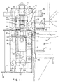
- the filter and pressure relief assembly constructed in accordance with the principles of the present invention for use in conjunction with an adhesive supply unit, is generally indicated by the reference character 10.
- the assembly 10 is fixedly mounted upon an adhesive supply hopper 12 by means of a plurality of screw or bolt fasteners 14, and the assembly 10 comprises a filter block 16 within which is defined a pair of substantially vertically extending cavities 18.
- a filter basket 20 is disposed within the lower part or end of each one of the cavities 18, while a filter plug 22 is disposed within the upper part or end of each one of the cavities 18.
- each one of the filter plugs 22 is seen to comprise a first, lower, horizontal through-bore 24 and a second, upper, horizontal through-bore 26, and a first, lower, vertical passageway or bore 28 fluidically intersecting and connected to the first, lower, horizontal through-bore 24, and a second, upper, vertical passageway or bore 30 fluidically intersecting and interconnecting the upper and lower horizontal through-bores 24 and 26.
- the filter block 16 is further provided with respective inlet bores or passageways 32 through which adhesive is conducted respectively into the cavities 18 by means of a suitable pump, not shown, operatively disposed within the adhesive supply unit of which the supply hopper 12 is a component part.
- the filter block 16 is further provided with a first pair of hose outlets 36 which are in fluidic communication, at one respective side thereof, with the lower end or part of each one of the cavities 18, and at an opposite respective side thereof with an outlet hose, not shown, which is operatively associated with and connected to an adhesive applicator, also not shown.
- the adhesive flows from the supply hopper 12, through the supply conduit 34, through the inlet bores 32 of the filter block 16, into the cavities 18, through the first, lower, horizontal through-bores 24 of the filter plugs 22, downwardly through the first, lower, vertical passageways or bores 28 of the filter plugs 22, through the filter baskets 20, and out of the first pair of hose outlets 36 defined within the filter block 16 such that the adhesive can be discharged or applied, in accordance with a predetermined adhesive application, by means of the outlet hoses and the adhesive applicator, not shown.
- each filter plug 22 is provided with an enlarged bore 38 which is fluidically connected to the second, upper, vertical passageway or bore 30 as well as to the second, upper, horizontal through-bore 26.
- the enlarged bore 38 and the second, upper, vertical bore 30 have an annular shoulder portion 40 defined therebetween, and the radially inner peripheral edge portion of the shoulder portion 40 defines a valve seat 42 upon which a valve member 44 is normally seated.
- the valve member 44 is normally biased toward and onto its valve seat 42 by means of a spring member 46 which is disposed within the enlarged bore 38.
- the uppermost, open ended portion of the bore 38 is internally threaded so as to define a threaded socket 48, and a set screw 50 is threadedly engaged within the socket 48 so as to impress a predetermined amount of compression upon the spring member 46 whereby the valve member 44 will be unseated from its valve seat 42 by means of a predetermined amount of pressure within the adhesive flow system, and as more particularly determined by means of the pressure of the adhesive within the vertical bore 30, as variably or adjustably determined by means of the set screw 50.
- the threaded disposition or axial position of the set screw 50 with respect to the threaded socket 48 of the filter plug 22 may be fixed by means of a lock nut 52.
- the filter block 16 is provided with a second pair of return ports 54 which are in fluidic communication, at one respective side thereof, with an upper end or part of each one of the cavities 18, and at an opposite respective side thereof with a return hose or conduit 56 which, in turn, is operatively connected at its opposite end to the supply hopper 12.
- a check valve 58 is disposed within conduit 56 so as to ensure fluid flow of the adhesive within conduit 56 back toward the supply hopper 12.
- pressure taps are provided at predetermined locations both upstream and downstream of the filter baskets 20.
- pressure data can be generated so as to provide operator personnel, for example, with indications of the proper functioning of the filters 20 of the system or the improper functioning thereof due, for example, to clogging of the same with debris whereby replacement of the filters 20 would be necessitated.
- the upstream pressure taps are shown at 60 as being operatively associated with the inlet bores 32, while the downstream pressure taps are illustrated at 62, and thus, the provision of such pressure taps 60 and 62 can be used to optimize filter change intervals.
- the operator personnel may detect clogged filter conditions, for example, or the improper temperature control of the adhesive material which would impart to the adhesive material improper viscosity characteristics, by abnormal flow characteristics of the adhesive material through the adhesive applicator. Either case, would probably necessitate replacement of the filter baskets 20.
- the present invention is therefore also concerned with the provision of a system by means of which the filter baskets 20 can be replaced or exchanged in a safe manner without operator personnel being exposed to operational hazards.
- spring members 64 in the form of, for example, perforate wave springs, are interposed between the upper ends of the filter baskets 20 and the lower ends of the filter plugs 22 so as to, in effect, bias the filter baskets 20 downwardly within the lower end portions of the cavities 18 while biasing the filter plugs 22 upwardly within the upper end portion C of the cavities 18.
- the wave spring members 64 are of course perforate so as to permit the adhesive material to flow therethrough from the filter plugs 22 and into the filter baskets 20.
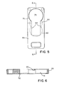
- a slide plate 66 is operatively engaged with each one of the filter plugs 22.
- a slide frame 68 is secured to the upper part of the filter block 16 by means of suitable screw or bolts fasteners 70 so as to slidably house the slide plates 66 upon the filter block 16.
- the upper portion of each filter plug 22 comprises an annular shoulder portion 72 and a pair of flats 74 disposed upon diametrically opposite sides of the plug 22.
- Each slide plate 66 has a key-hole shaped slot 76 defined therein wherein the key-hole shaped slot 76 includes a through-bore portion 78 which corresponds to a first one of three slidable positions of the slide plate 66, with respect to the slide frame 68 and filter block 16, at which the through-bore portion 78 of the slide plate 66 will be coaxially disposed with respect to its associated filter plug 22 and filter basket 20 so as to permit removal of the latter components from the filter block 16.
- the slide plate 66 further comprises first and second undercut or counterbored portions 80 and 82 which define second and third slidable positions of the slide plate 66, with respect to the slide frame 68 and the filter block 16, at which the respective filter plug 22 is disposed within the filter block 16 at its partially inserted or retained position, and at its fully inserted or retained position, respectively, as will soon be more fully explained and understood hereinafter.
- the slideframe 68 is of course provided with a pair of through-bores 86 which are adapted to be coaxially aligned with the throughbore portion 78 of the slide plate 66 when the latter is disposed at its first position with respect to the slide frame 68 so as to permit the filter plugs 22 and the filter baskets 20 to be removed from the filter 16 assembly.
- the slide frame 68 is further provided with a pair of slots 88 within substantially central portions thereof, the slots 88 extending inwardly from a side edge portion 90 of the slide frame 68.
- Each of the slide plates 66 is provided with a pair of apertures 92, only one of which is shown in FIGURE 1, and an upstanding guide pin 94 is adapted to be fixedly disposed within one of the apertures 92 of each plate 66 depending upon the particular disposition of the particular plate 66 with respect to the slide frame 68 as best seen in FIGURE 7.
- each of the filter plugs 22 is provided with vertically or axially spaced annularly or peripherally recessed portions 96 and 98 which are adapted to house secondary and primary O-ring sealing members 100 and 102, respectively.
- a central region 104 of each filter block cavity 18 has a first predetermined diametrical extent, while an upper region 106 of each filter block cavity 18 has a second predetermined diametrical extent which is larger than the first predetermined diametrical extent of the central region 104.
- the O-ring members 102 and 100 respectively engage internal peripheral wall portions of the central and upper regions 104 and 106, respectively, so as to provide sealing for the filter plug assemblies 22 with respect to the cavities 18 of the filter blocks 16.
- the provision of the two O-ring sealing members 100 and 102 serves two primary functions.
- a first one of the two primary functions encompasses sealing redundancy so as to provide the system with a safety feature or procedure should, for example, the primary O-ring sealing member 102 experience failure.
- the secondary O-ring sealing member 100 would nevertheless provide the sealing capabilities to the system whereby, for example, the hot adhesive would not be forcefully discharged out of the filter block 16 and thereby present a safety hazard to operator personnel, and would be routed back to hopper 12 through ports 54.
- the second primary function of providing the two sealing members 100 and 102 also encompasses safety procedures in connection with the filter and pressure relief assembly 10 of the present invention, particularly in connection with the exchange or replacement of the filter baskets 20 when in fact they need to be changed or replaced.
- adhesive is supplied to or conducted into the filter block cavities 18 by means of the inlet passageways or ports 32 operatively connected to the adhesive supply conduit 34, pressurized adhesive will be disposed within the cavities 18 at elevational levels which are beneath the lower peripheral recessed portion 98 and the primary O-ring sealing member 102.
- the filter plug assemblies 22 are constantly biased in an upward direction within the filter block cavities 18, however, the filter plug assemblies 22 are of course fixedly retained within the filter block 16 by means of the slide plate 66 and slide frame 68 components as noted hereinbefore, that is, when the slide 5 plate 66 is disposed at its second or third positions 80 and 82 corresponding to the partially or fully retained positions of the filter plug assemblies 22 with respect to the filter block 16.
- the slide plate 66 When the filter plugs 22 and the filter baskets 20 are to be removed from the filter block 16 so as to permit maintenance work to be performed upon the filter baskets 20, or alternatively, replacement of the filter baskets 20, the slide plate 66 must of course be moved to its first position 78 which corresponds to the full release position at which the filter plugs 22 and the filter baskets 20 may in fact be removed from the filter block 16.
- pressure within the system must first be relieved such that hot adhesive is not forcefully discharged or ejected from the filter block 16 and thereby present a safety hazard for operator personnel.
- the slide plates 66 are able to be moved from their third, full retention positions 82 to their second, partial release positions 80 as a result of the disengagement of the shoulder portions 72 of the filter plugs 22 with respect to the counter bored sections 82 of the slide plates 66.
- the filter plugs 22 Upon movement of the slide plates 66 to their second, partial release positions 80, and in view of the particular provision or disposition of the counterbored structures or undercut portions 80 and 82, as best seen in FIGURE 6, when the filter plugs 22 are released from their depressed states, the filter plugs 22 will rise within the cavities 18 until the shoulder portions 72 of the plugs 22 engage the undercut or counterbored portions 80 of the slide plates 66, the filter plugs 22 rising under the influence of the wave spring members 64 returning to their normal, non-depressed positions, as well as under the influence of the residual adhesive pressure within the system.
- the lower primary O-ring members 102 are now disposed within the enlarged diameter upper regions 106 of the filter block cavities 18, are therefore no longer engaged in sealing relationship with the smaller diameter central regions 104 of the filter block cavities 18, and are similarly not engaged in sealing relationship with the larger diameter upper regions 106 of the cavities 18 due to the differences in diametrical extents. Consequently, adhesive, disposed within the cavities 18 and exhibiting the previously noted residual pressure, can now, in effect, escape around the lower primary O-ring members 102 so as to flow back toward the supply hopper 12 through means of the return ports 54.
- the slide plates 66 can be moved from their second, partial release positions 80 to their first, full release positions 78,after the filter plugs 22 have again been depressed, such that the shoulder portions 72 of the plugs 22 clear the counterbored portions 80 of the slide plates 66, whereby the filter plug 22 and the filter baskets 20 can be safely removed from the filter block 16 without any danger of hot adhesive being force fully discharged or ejected from the filter block 16 and there by otherwise presenting a safety hazard to operator personnel.
- the filter plugs 22 and filter baskets 20 can be removed from the system filter block 16 as a result of the particular interoperative structure comprising the slide plates 66 and the slide frame 68 without the necessity or requirement of using specialized tools.
- the filter block 16 is adapted to be heated to a temperature level of approximately 375°F (190°C), and accordingly, a suitable heating component 108 is disposed in operative association with a lower portion of filter block 16, while a temperature sensor 110 is disposed within the vicinity of component 108 so as to sense or determine the temperature level of block 16 and control component 108 through an electronic temperature controller, not shown.
- a clamp plate 112 fixedly secures heater 108 and sensor 110 to a lower portion of block 16.
- Heater 108 can comprise any suitable type of heater, such as an electrical resistance type, a conduit for heated water or combustion gases, and the like.
- a circuit breaker or resettable switch 114 is also provided upon block 16 within the vicinity of spring washers 64 so as to redundantly terminate power to heater 108 if excessive temperature levels are sensed by means of the temperature sensor 110.
- a heat insulating plate 116 is interposed between filter block 16 and supply hopper 12, and the filter block 16 has a junction box 118 operatively connected thereto or mounted thereon for housing the various electrical power supply components required for operation of the various components comprising the filter and pressure relief assembly 10 of the invention.
- the present invention incorporates significant safety features or structural components within the overall filter and adhesive supply system so as to render the operation of the system safe and secure, and in addition, to facilitate the safe and secure replacement of the filter baskets or modules within the overall system.
- the overall system is provided with redundancy sealing capabilities during operation of the system.
- such dual O-ring sealing system provides controlled pressure relief for the system when the filter baskets or modules are to be serviced, replaced, or exchanged. Replacement of the filter baskets or modules is also substantially impossible to achieve while the system is being operated under normal operations and pressures whereby operation of the system supply pumps must initially be terminated or shut-down.
- a cross channel 120 which is normally closed by means of a plug 122 disposed internally within the channel 120, may be opened by removing such plug 122, whereby operative pressure conditions, for example, within the two filter modules comprising in particular the filter baskets 20 are equalized.
- An access plug 124 is provided within the right side end of the filter block 16 so as to provide access to the cross channel 120 and the plug 122 normally disposed therein.
Landscapes
- Engineering & Computer Science (AREA)
- Mechanical Engineering (AREA)
- Chemical & Material Sciences (AREA)
- Chemical Kinetics & Catalysis (AREA)
- Filtration Of Liquid (AREA)
- Coating Apparatus (AREA)
- Application Of Or Painting With Fluid Materials (AREA)
- Electrical Discharge Machining, Electrochemical Machining, And Combined Machining (AREA)
- Fluid-Pressure Circuits (AREA)
Applications Claiming Priority (2)
| Application Number | Priority Date | Filing Date | Title |
|---|---|---|---|
| US08/610,087 US5672269A (en) | 1996-02-29 | 1996-02-29 | Filter/pressure relief assembly for an adhesive supply unit |
| US610087 | 1996-02-29 |
Publications (2)
| Publication Number | Publication Date |
|---|---|
| EP0792675A1 true EP0792675A1 (fr) | 1997-09-03 |
| EP0792675B1 EP0792675B1 (fr) | 2003-05-07 |
Family
ID=24443586
Family Applications (1)
| Application Number | Title | Priority Date | Filing Date |
|---|---|---|---|
| EP97301195A Expired - Lifetime EP0792675B1 (fr) | 1996-02-29 | 1997-02-24 | Ensemble de détente et de filtration |
Country Status (5)
| Country | Link |
|---|---|
| US (1) | US5672269A (fr) |
| EP (1) | EP0792675B1 (fr) |
| JP (1) | JP3930091B2 (fr) |
| AT (1) | ATE239538T1 (fr) |
| DE (1) | DE69721613T2 (fr) |
Cited By (1)
| Publication number | Priority date | Publication date | Assignee | Title |
|---|---|---|---|---|
| CN117160123A (zh) * | 2023-11-02 | 2023-12-05 | 福建省德尚电子材料有限公司 | 一种光刻胶滤芯更换用管路结构 |
Families Citing this family (6)
| Publication number | Priority date | Publication date | Assignee | Title |
|---|---|---|---|---|
| US6260583B1 (en) * | 2000-05-24 | 2001-07-17 | Illinois Tool Works Inc. | Segmented stackable head design |
| US6406625B1 (en) | 2000-10-31 | 2002-06-18 | Nordson Corporation | Spring-biased filter assembly |
| US6799702B1 (en) | 2000-11-22 | 2004-10-05 | Gopro, Inc. | Device for dispensing viscous liquids |
| US9090002B2 (en) * | 2011-10-06 | 2015-07-28 | Kolcor Technologies LLC | Sealing device in a polymer filtration device |
| EP3308940B1 (fr) * | 2016-10-17 | 2025-03-05 | Next Generation Analytics GmbH | Système de filtre pour les fluides visqueux ou fortement visqueux, surtout plastique fondu et procédé de filtration des liquides visqueux ou fortement visqueux |
| US11260570B2 (en) * | 2018-05-07 | 2022-03-01 | PSI-Polymer Systems, Inc. | Filtration apparatuses and screen changer devices for polymer processing and related methods |
Citations (4)
| Publication number | Priority date | Publication date | Assignee | Title |
|---|---|---|---|---|
| US3815788A (en) * | 1972-10-24 | 1974-06-11 | Nordson Corp | Thermoplastic applicator including a removable filter |
| US3825121A (en) * | 1973-06-01 | 1974-07-23 | Gk Syst Inc | Apparatus for the continuous filtration of thermoplastic or elastomeric materials used in extrusion processes |
| US4200207A (en) * | 1978-02-01 | 1980-04-29 | Nordson Corporation | Hot melt adhesive foam pump system |
| EP0171511A2 (fr) * | 1984-05-30 | 1986-02-19 | Nordson Corporation | Procédé et appareil pour la régulation du contenu de gaz d'une colle mousseuse thermoplastique chaude |
Family Cites Families (3)
| Publication number | Priority date | Publication date | Assignee | Title |
|---|---|---|---|---|
| FR1399683A (fr) * | 1964-04-08 | 1965-05-21 | Rhone Poulenc Sa | Perfectionnement aux dispositifs de filtration dans l'extrusion des matières plastiques |
| US3912630A (en) * | 1972-10-24 | 1975-10-14 | Nordson Corp | Filter cartridge for thermoplastic applicator system |
| US5192425A (en) * | 1991-07-22 | 1993-03-09 | Wagner Spray Tech Corporation | Mounting base and assembly for pressure sensor, filter and pressure relief valve |
-
1996
- 1996-02-29 US US08/610,087 patent/US5672269A/en not_active Expired - Lifetime
-
1997
- 1997-02-24 DE DE69721613T patent/DE69721613T2/de not_active Expired - Lifetime
- 1997-02-24 EP EP97301195A patent/EP0792675B1/fr not_active Expired - Lifetime
- 1997-02-24 AT AT97301195T patent/ATE239538T1/de not_active IP Right Cessation
- 1997-02-28 JP JP04570997A patent/JP3930091B2/ja not_active Expired - Lifetime
Patent Citations (4)
| Publication number | Priority date | Publication date | Assignee | Title |
|---|---|---|---|---|
| US3815788A (en) * | 1972-10-24 | 1974-06-11 | Nordson Corp | Thermoplastic applicator including a removable filter |
| US3825121A (en) * | 1973-06-01 | 1974-07-23 | Gk Syst Inc | Apparatus for the continuous filtration of thermoplastic or elastomeric materials used in extrusion processes |
| US4200207A (en) * | 1978-02-01 | 1980-04-29 | Nordson Corporation | Hot melt adhesive foam pump system |
| EP0171511A2 (fr) * | 1984-05-30 | 1986-02-19 | Nordson Corporation | Procédé et appareil pour la régulation du contenu de gaz d'une colle mousseuse thermoplastique chaude |
Cited By (2)
| Publication number | Priority date | Publication date | Assignee | Title |
|---|---|---|---|---|
| CN117160123A (zh) * | 2023-11-02 | 2023-12-05 | 福建省德尚电子材料有限公司 | 一种光刻胶滤芯更换用管路结构 |
| CN117160123B (zh) * | 2023-11-02 | 2024-02-13 | 福建省德尚电子材料有限公司 | 一种光刻胶滤芯更换用管路结构 |
Also Published As
| Publication number | Publication date |
|---|---|
| JP3930091B2 (ja) | 2007-06-13 |
| EP0792675B1 (fr) | 2003-05-07 |
| DE69721613T2 (de) | 2004-03-25 |
| US5672269A (en) | 1997-09-30 |
| DE69721613D1 (de) | 2003-06-12 |
| JPH09327607A (ja) | 1997-12-22 |
| ATE239538T1 (de) | 2003-05-15 |
Similar Documents
| Publication | Publication Date | Title |
|---|---|---|
| US5590684A (en) | Dual pilot manifold assembly for a safety relief valve | |
| CA2638610C (fr) | Collecteur a isolement hydraulique | |
| JP7171093B2 (ja) | ガスの充填及び回収装置 | |
| DE102013105910A1 (de) | Elektronisch steuerbares und prüfbares Turbinenschnellschlusssystem und Verfahren mit redundanten Ablassverteilern | |
| US5672269A (en) | Filter/pressure relief assembly for an adhesive supply unit | |
| EP2106229B1 (fr) | Soupape de sécurité pour une machine de préparation de boissons par percolation | |
| EP1780472A2 (fr) | Ensemble pour alimenter en eau des installations de chauffage comprenant un chauffe-eau | |
| DE3836878C2 (de) | Sicherheitsabsperrventil | |
| JPS6191569A (ja) | 液体クロマトグラフイー用の溶媒加圧系 | |
| JPH10187247A (ja) | 制御弁システム | |
| EP0736155B1 (fr) | Robinet haute pression | |
| EP1548293B1 (fr) | Une unité integrée pour le traitement de l'air des systèmes pneumatiques | |
| DE19854301C2 (de) | Gasdruckregler mit Überdrucksicherung | |
| WO1992011639A1 (fr) | Dispositif pour assurer la resistance a la pression d'un recipient sous pression | |
| US20020036016A1 (en) | Hydraulic line connection | |
| CA2230480C (fr) | Ensemble collecteur double de commande de soupape de surete | |
| DE10232654B3 (de) | Gasdurchflussregeleinrichtung | |
| RU2648435C2 (ru) | Модуль сброса давления | |
| CA2547602C (fr) | Ensemble collecteur double de commande de soupape de surete | |
| DE3805547C2 (de) | Zulaufventil | |
| DE3324972C2 (de) | Schlauchbruchsicherung mit Leckgasprüfeinrichtung | |
| US5450872A (en) | Constant pressure valve and method |
Legal Events
| Date | Code | Title | Description |
|---|---|---|---|
| PUAI | Public reference made under article 153(3) epc to a published international application that has entered the european phase |
Free format text: ORIGINAL CODE: 0009012 |
|
| AK | Designated contracting states |
Kind code of ref document: A1 Designated state(s): AT CH DE FR GB IT LI |
|
| 17P | Request for examination filed |
Effective date: 19980220 |
|
| 17Q | First examination report despatched |
Effective date: 20020816 |
|
| GRAH | Despatch of communication of intention to grant a patent |
Free format text: ORIGINAL CODE: EPIDOS IGRA |
|
| GRAH | Despatch of communication of intention to grant a patent |
Free format text: ORIGINAL CODE: EPIDOS IGRA |
|
| GRAA | (expected) grant |
Free format text: ORIGINAL CODE: 0009210 |
|
| AK | Designated contracting states |
Designated state(s): AT CH DE FR GB IT LI |
|
| PG25 | Lapsed in a contracting state [announced via postgrant information from national office to epo] |
Ref country code: LI Free format text: LAPSE BECAUSE OF FAILURE TO SUBMIT A TRANSLATION OF THE DESCRIPTION OR TO PAY THE FEE WITHIN THE PRESCRIBED TIME-LIMIT Effective date: 20030507 Ref country code: FR Free format text: LAPSE BECAUSE OF FAILURE TO SUBMIT A TRANSLATION OF THE DESCRIPTION OR TO PAY THE FEE WITHIN THE PRESCRIBED TIME-LIMIT Effective date: 20030507 Ref country code: CH Free format text: LAPSE BECAUSE OF FAILURE TO SUBMIT A TRANSLATION OF THE DESCRIPTION OR TO PAY THE FEE WITHIN THE PRESCRIBED TIME-LIMIT Effective date: 20030507 Ref country code: AT Free format text: LAPSE BECAUSE OF FAILURE TO SUBMIT A TRANSLATION OF THE DESCRIPTION OR TO PAY THE FEE WITHIN THE PRESCRIBED TIME-LIMIT Effective date: 20030507 |
|
| REG | Reference to a national code |
Ref country code: GB Ref legal event code: FG4D |
|
| REG | Reference to a national code |
Ref country code: CH Ref legal event code: EP |
|
| REF | Corresponds to: |
Ref document number: 69721613 Country of ref document: DE Date of ref document: 20030612 Kind code of ref document: P |
|
| REG | Reference to a national code |
Ref country code: CH Ref legal event code: PL |
|
| PG25 | Lapsed in a contracting state [announced via postgrant information from national office to epo] |
Ref country code: GB Free format text: LAPSE BECAUSE OF NON-PAYMENT OF DUE FEES Effective date: 20040224 |
|
| PLBE | No opposition filed within time limit |
Free format text: ORIGINAL CODE: 0009261 |
|
| STAA | Information on the status of an ep patent application or granted ep patent |
Free format text: STATUS: NO OPPOSITION FILED WITHIN TIME LIMIT |
|
| 26N | No opposition filed |
Effective date: 20040210 |
|
| EN | Fr: translation not filed | ||
| GBPC | Gb: european patent ceased through non-payment of renewal fee |
Effective date: 20040224 |
|
| PGFP | Annual fee paid to national office [announced via postgrant information from national office to epo] |
Ref country code: IT Payment date: 20160223 Year of fee payment: 20 Ref country code: DE Payment date: 20160226 Year of fee payment: 20 |
|
| REG | Reference to a national code |
Ref country code: DE Ref legal event code: R071 Ref document number: 69721613 Country of ref document: DE |