EP0792692A1 - Düse zur beseitigung von kesselstein - Google Patents
Düse zur beseitigung von kesselstein Download PDFInfo
- Publication number
- EP0792692A1 EP0792692A1 EP96932814A EP96932814A EP0792692A1 EP 0792692 A1 EP0792692 A1 EP 0792692A1 EP 96932814 A EP96932814 A EP 96932814A EP 96932814 A EP96932814 A EP 96932814A EP 0792692 A1 EP0792692 A1 EP 0792692A1
- Authority
- EP
- European Patent Office
- Prior art keywords
- orifice
- nozzle
- liquid
- passage
- jetting direction
- Prior art date
- Legal status (The legal status is an assumption and is not a legal conclusion. Google has not performed a legal analysis and makes no representation as to the accuracy of the status listed.)
- Granted
Links
Images




Classifications
-
- B—PERFORMING OPERATIONS; TRANSPORTING
- B21—MECHANICAL METAL-WORKING WITHOUT ESSENTIALLY REMOVING MATERIAL; PUNCHING METAL
- B21B—ROLLING OF METAL
- B21B45/00—Devices for surface or other treatment of work, specially combined with or arranged in, or specially adapted for use in connection with, metal-rolling mills
- B21B45/04—Devices for surface or other treatment of work, specially combined with or arranged in, or specially adapted for use in connection with, metal-rolling mills for de-scaling, e.g. by brushing
- B21B45/08—Devices for surface or other treatment of work, specially combined with or arranged in, or specially adapted for use in connection with, metal-rolling mills for de-scaling, e.g. by brushing hydraulically
-
- B—PERFORMING OPERATIONS; TRANSPORTING
- B05—SPRAYING OR ATOMISING IN GENERAL; APPLYING FLUENT MATERIALS TO SURFACES, IN GENERAL
- B05B—SPRAYING APPARATUS; ATOMISING APPARATUS; NOZZLES
- B05B1/00—Nozzles, spray heads or other outlets, with or without auxiliary devices such as valves, heating means
-
- B—PERFORMING OPERATIONS; TRANSPORTING
- B05—SPRAYING OR ATOMISING IN GENERAL; APPLYING FLUENT MATERIALS TO SURFACES, IN GENERAL
- B05B—SPRAYING APPARATUS; ATOMISING APPARATUS; NOZZLES
- B05B1/00—Nozzles, spray heads or other outlets, with or without auxiliary devices such as valves, heating means
- B05B1/02—Nozzles, spray heads or other outlets, with or without auxiliary devices such as valves, heating means designed to produce a jet, spray, or other discharge of particular shape or nature, e.g. in single drops, or having an outlet of particular shape
- B05B1/04—Nozzles, spray heads or other outlets, with or without auxiliary devices such as valves, heating means designed to produce a jet, spray, or other discharge of particular shape or nature, e.g. in single drops, or having an outlet of particular shape in flat form, e.g. fan-like, sheet-like
- B05B1/042—Outlets having two planes of symmetry perpendicular to each other, one of them defining the plane of the jet
-
- B—PERFORMING OPERATIONS; TRANSPORTING
- B05—SPRAYING OR ATOMISING IN GENERAL; APPLYING FLUENT MATERIALS TO SURFACES, IN GENERAL
- B05B—SPRAYING APPARATUS; ATOMISING APPARATUS; NOZZLES
- B05B1/00—Nozzles, spray heads or other outlets, with or without auxiliary devices such as valves, heating means
- B05B1/34—Nozzles, spray heads or other outlets, with or without auxiliary devices such as valves, heating means designed to influence the nature of flow of the liquid or other fluent material, e.g. to produce swirl
- B05B1/3402—Nozzles, spray heads or other outlets, with or without auxiliary devices such as valves, heating means designed to influence the nature of flow of the liquid or other fluent material, e.g. to produce swirl to avoid or reduce turbulence, e.g. with fluid flow straightening means
Definitions
- the present invention relates to descaling nozzles, and particularly to a descaling nozzle having a nozzle body formed of cemented carbide and defining a liquid passage having a diameter reducing as it extends downstream with respect to a liquid jetting direction, and a orifice in the form of a slot when seen in the liquid jetting direction and having an inlet communicating with a downstream position with respect to the liquid jetting direction of the liquid passage, for causing a high-pressure liquid jetting from the orifice to collide with a metal surface to remove scales from the metal surface.
- the high-pressure water When the jetting high-pressure water is collected for repeated use, the high-pressure water contains fine scales ad the like. The fine scales and the like further accelerate the wear.
- the nozzle body may be formed of a carbide hard metal containing tungsten (W) as its main component.
- W tungsten
- a nozzle tip 01 acting as a nozzle body includes a groove 03 of U-shaped cross section formed in a distal end thereof ad crossing a high-pressure water discharge passage 02 in a downstream position with respect to a high-pressure water jetting direction.
- An elongated (when seen in the high-pressure water jetting direction) orifice 04 is formed at the intersection of the high-pressure water discharge passage 02 and the groove 03.
- Orifice peripheries 05 define thin wall portions 06 in the form of knife edges in bottoms of the groove 03 and at longitudinal positions of the orifice (Japanese Laid-open Patent Application No. 1-111464).
- the thin wall portions 06 tend to be worn away or chipped as indicated by dot-and-dash lines in Fig. 13.
- the orifice peripheries 05 are damaged quickly, resulting in a deformation of the orifice 04 and a reduction in the jetting pressure of the ultrahigh-pressure water to become unable to remove scales efficiently.
- the durability of the orifice peripheries 05 cannot be improved.
- the thin wall portions 06 are more susceptible to chipping due to the fine scales colliding with the thin wall portions 06.
- Ultrahigh-pressure water jetting from one descaling nozzle may splash in the longitudinal direction of the groove 03 of another descaling nozzle and collide with the thin wall portions 06 of that nozzle tip 01. This may also result in early damage of the orifice peripheries 05.
- the present invention has been devised to solve these drawbacks of the prior art, and its object is to provide a descaling nozzle which includes orifice peripheries of improved configuration whereby the orifice peripheries have increased wear resistance against ultrahigh-pressure water, and which effectively prevents the orifice peripheries from being damaged due to a decrease in the impact resistance resulting from the increased wear resistance.
- a nozzle body formed of cemented carbide defines;
- the concave section and an inner surface of the liquid passage may form a large angle across orifice peripheries through the entire circumference of the orifice.
- the orifice peripheries may be thick-walled in the liquid jetting direction through the entire circumference of the orifice.
- the outlet of the orifice is entirely surrounded by the annular forward end protruding in the liquid jetting direction. There is little possibility of high-pressure water jetting from a different descaling nozzle splashing back and colliding with the outlet of the orifice.
- the forward end having an annular shape integrally surrounding the entire outer circumference of the concave section provides a reinforced structure to cope with severe conditions, compared with a forward end formed by a separate element.
- the hardness of the cemented carbide forming the nozzle body may be increased to enhance wear resistance of the orifice peripheries against ultrahigh-pressure water, and at the same time the orifice peripheries may be prevented from being damaged soon due to a decrease in the impact resistance resulting from the increased hardness of the cemented carbide.
- a construction as shown in Figs. 4 and 6 can be realized.
- said cemented carbide has a Rockwell hardness (HRA) of 94.0 or higher by A Graduation of Rockwell hardness test stipulated in the Japanese Industrial Standards.
- This construction can prevent, with greater effect, the orifice peripheries from being damaged soon, to realize a descaling nozzle having increased durability.
- Nozzle bodies shaped according to the present invention were manufactured by using cemented carbide A, B, and C whose Rockwell hardness (HRA) was 88.7, 90.7, and 94.0, respectively. Each of these nozzle bodies was attached to a descaling noble. Each descaling nozzle was used to jet high-pressure water with a pumping pressure of 15.7 MPa for a fixed time period (about five weeks) under the same conditions, and a flow increase rate accompanying damage to the orifice peripheries was measured. As shown in Fig. 9, the descaling nozzles employing the nozzle bodies formed of cemented carbide A and B had very high flow increase rates. By contrast, the dealing nozzle with the nozzle body formed of cemented carbide C had a minimal increase rate.
- HRA Rockwell hardness
- the concave section of the descaling nozzle of the present invention is formed to be out of contact with the high-pressure liquid jetting from said orifice.
- the concave section is hardly worn away or chipped.
- a jet pattern of the high-pressure water does not change with the shape of the concave section. Consequently, the jet pattern may be maintained in a predetermined pattern without difficulty.
- an inner surface is formed through an inner circumference of said orifice to extend parallel to a orifice axis and between an inlet and an outlet of said orifice.
- the orifice peripheries 13 can be further thick-walled in the liquid jetting direction.
- an inlet-side corner 15 and an outlet-side corner 16 of the orifice peripheries 13 may define obtuse angles, to reinforce the orifice peripheries 13 to prevent early damage thereof with increased effect.
- Fig. 1 shows a descaling device in this embodiment.
- This descaling device has a descaling nozzle 1 fixed to an adapter P2 for removing scales from a steel plate surface. As shown in Fig. 4, the descaling device removes scales from a surface of rolled steel plate by jetting high-pressure water W as high-pressure liquid with a pumping pressure of 15 to 60 Mpa, in a thin band spray pattern S to the surface of steel plate.
- the descaling nozzle 1 includes a cylindrical passage forming member 2, a filter 3 screwed to one end of the passage forming member 2, and a jet passage forming member 4 screwed to the other end of the passage forming member 2.
- the passage forming member 2 has, formed coaxially with each other, a straightening passage 2a with a straightening device 5 mounted therein, and a restricting passage 2b continuous with a downstream end of the straightening passage 2a.
- the jet passage forming member 4 has a nozzle tip 7 coaxially press-fit in a nozzle case 6 to act as a nozzle body formed of carbide hard metal containing tungsten as a main component thereof.
- a bush 9 is mounted between the nozzle tip 7 and the passage forming member 2, and a jet passage 8 is formed downstream of the restricting passage 2b to continuous and coaxial therewith.
- the adapter P2 is attached to a main pipe P1 in the form of a branch pipe.
- the descaling nozzle 1 is inserted into the adapter P2 with the filter 3 protruding into the main pipe P1.
- a packing is disposed between a flange 6a of the nozzle case 6 and an end of the adapter P2, and the nozzle case 6 is fixed tight to the adapter P2 with a cap nut 10.
- the descaling nozzle 1 is fixed to the main pipe P1.
- the nozzle tip 7 is formed of cemented carbide whose Rockwell hardness in A Graduation of Rockwell hardness test (HRA) stipulated by JIS Standard (Japanese Industrial Standard) is about 94.0.
- HRA Rockwell hardness in A Graduation of Rockwell hardness test
- the nozzle tip 7 has a high-pressure water discharge passage 7a defining a downstream end of the jet passage 8 and having a diameter reducing as it extends downstream with respect to a high-pressure water jetting direction, and an orifice 7b having an elongated (elliptic) shape when seen in the high-pressure water jetting direction, with an inlet thereof communicating with the end of the high-pressure water discharge passage 7a downstream with respect to the high-pressure waterjetting direction.
- the orifice 7b jets out high-pressure water W against the surface of steel plate, thereby removing scales from the surface of steel plate.
- the nozzle tip 7 has, formed on an end portion 11 forward with respect to the high-pressure water jetting direction, a flat surface 11a extending at tight angles to the high-pressure water jetting direction.
- the flat surface 11a has in its center a conical concave section 12 of elliptical shape when seen in the high-pressure water jetting direction, having a diameter reducing as it extends upstream with respect to the high-pressure water jetting direction.
- the end portion 11 has an annular shape integrally surrounding the entire outer circumference of the concave section 12.
- the orifice 7b has an outlet opening to the entire bottom of the concave section 12.
- Orifice peripheries 13 are thick-walled in the high-pressure water jetting direction throughout the entire circumference of the orifice 7b.
- an inner surface 14 having a small width (about 0.2mm in the embodiment) and extending parallel to orifice axis X.
- the concave section 12 has an opening angle (set to about 60o.
- the high-pressure water W jets out of the orifice 7b at a jetting angle (of about 27o to be clear of the concave section 12.
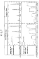
- a descaling nozzle employing the nozzle tip 01 of conventional shape shown in Fig. 12 and a descaling nozzle employing the nozzle tip 7 shaped according to the present invention were manufactured to provide the same flow rate and jetting angle (. Then, impact distributions were measured with a pressure sensor Q as shown in Fig. 8, by setting pumping pressure at 14.7 MPa, 29.4 MPa, 49.0 MPa and 62.8MPa. The results are shown in Fig. 7. It is seen from Fig. 7 that there is little difference between the impact distribution obtained from the nozzle tip 01 having the conventional shape and the impact distribution obtained from the nozzle tip 7 shaped according to the present invention.
- Nozzle bodies shaped according to the present invention were manufactured by using cemented carbide A, B, and C whose Rockwell hardness (HRA) was 88.7, 90.7, and 94.0, respectively. Each of these nozzle bodies was attached to a descaling nozzle. Each descaling nozzle was used to jet high-pressure water with a pumping pressure of 15.7 MPa for a fixed time period (about five weeks) under the same conditions, and a flow increase rate accompanying damage to the orifice 7b was measured. The results shown in percentage in Fig. 9 indicate that the descaling nozzles employing the nozzle bodies formed of cemented carbide A and B had very high flow increase rates. By contrast, the descaling nozzle with the nozzle body formed of cemented carbide C had a minimal increase rate.
- HRA Rockwell hardness
- Varied methods are available for manufacturing cemented carbide having a Rockwell hardness (HRA) of 94.0 or higher.
- HRA Rockwell hardness
- it can easily be obtained by making particles of a carbide intermetallic compound (such as WC) uniform and fine (e.g. 1(m or less in diameter) or by adding a proper amount of one or more metal carbides (or nitrides), such as titanium, tantalum, and vanadium, to the carbide intermetallic compound.
- Figs. 10 and 11 show an embodiment including no inner surface 14 formed throughout the inner circumference of the orifice 7b to be parallel to the orifice axis X as shown in the first embodiment Other aspects are the same as in the first embodiment.
- This embodiment can also provide a descaling nozzle having orifice peripheries of higher durability than in the prior art.
Landscapes
- Engineering & Computer Science (AREA)
- Mechanical Engineering (AREA)
- Physics & Mathematics (AREA)
- Fluid Mechanics (AREA)
- Nozzles (AREA)
Applications Claiming Priority (4)
| Application Number | Priority Date | Filing Date | Title |
|---|---|---|---|
| JP25600295A JP3494327B2 (ja) | 1995-10-03 | 1995-10-03 | スケール除去用ノズル |
| JP256002/95 | 1995-10-03 | ||
| JP25600295 | 1995-10-03 | ||
| PCT/JP1996/002886 WO1997012684A1 (en) | 1995-10-03 | 1996-10-02 | Scale removing nozzle |
Publications (3)
| Publication Number | Publication Date |
|---|---|
| EP0792692A1 true EP0792692A1 (de) | 1997-09-03 |
| EP0792692A4 EP0792692A4 (de) | 1999-03-17 |
| EP0792692B1 EP0792692B1 (de) | 2002-08-07 |
Family
ID=17286547
Family Applications (1)
| Application Number | Title | Priority Date | Filing Date |
|---|---|---|---|
| EP96932814A Expired - Lifetime EP0792692B1 (de) | 1995-10-03 | 1996-10-02 | Düse zur beseitigung von kesselstein |
Country Status (9)
| Country | Link |
|---|---|
| US (1) | US5878966A (de) |
| EP (1) | EP0792692B1 (de) |
| JP (1) | JP3494327B2 (de) |
| KR (1) | KR100391488B1 (de) |
| AU (1) | AU713005B2 (de) |
| BR (1) | BR9607551A (de) |
| DE (1) | DE69622835T2 (de) |
| TW (1) | TW379592U (de) |
| WO (1) | WO1997012684A1 (de) |
Cited By (9)
| Publication number | Priority date | Publication date | Assignee | Title |
|---|---|---|---|---|
| EP1046426A2 (de) | 1999-04-22 | 2000-10-25 | Lechler GmbH & Co.KG | Hochdrucksprühdüse |
| EP1293258A1 (de) * | 2001-09-12 | 2003-03-19 | H. Ikeuchi & Co., Ltd. | Spritzdüse |
| WO2004058427A1 (en) * | 2002-12-25 | 2004-07-15 | Kyoritsu Gokin Co., Ltd. | Descaling nozzle |
| WO2004085075A1 (de) * | 2003-03-28 | 2004-10-07 | Daimlerchrysler Ag | Sprühkopf für hochdruckstrahlanwendungen |
| SG118253A1 (en) * | 2003-12-22 | 2006-01-27 | Jettech Ltd | Fan jet nozzle for use with ultra high pressure liquid phase cleaning media for use in deflashing apparatus |
| GB2441510A (en) * | 2006-09-08 | 2008-03-12 | R Munro-Walker | An energy saving nozzle |
| EP1992415A3 (de) * | 2007-05-15 | 2010-01-27 | Lechler GmbH | Hochdruckdüse und Verfahren zum Herstellen einer Hochdruckdüse |
| US20110030234A1 (en) * | 2009-07-31 | 2011-02-10 | Soowon Park | Clothes Dryer Having Liquid Injection Nozzle |
| US8079534B2 (en) | 2007-05-15 | 2011-12-20 | Lechler Gmbh | Spray nozzle |
Families Citing this family (22)
| Publication number | Priority date | Publication date | Assignee | Title |
|---|---|---|---|---|
| US6068887A (en) * | 1997-11-26 | 2000-05-30 | Kawasaki Steel Corporation | Process for producing plated steel sheet |
| US6752685B2 (en) | 2001-04-11 | 2004-06-22 | Lai East Laser Applications, Inc. | Adaptive nozzle system for high-energy abrasive stream cutting |
| US7621266B2 (en) * | 2003-01-14 | 2009-11-24 | Boehringer Ingelheim International Gmbh | Nozzle-system for a dispenser for fluids consisting of a nozzle and a nozzle-holder and/or screw cap |
| US7040959B1 (en) | 2004-01-20 | 2006-05-09 | Illumina, Inc. | Variable rate dispensing system for abrasive material and method thereof |
| KR100863227B1 (ko) * | 2004-11-10 | 2008-10-15 | 주식회사 나래나노텍 | 평탄부 및 리세스부를 구비한 노즐 단부 구조를 갖는 노즐디스펜서 및 그 제조 방법 |
| KR100765036B1 (ko) * | 2005-12-26 | 2007-10-09 | 주식회사 포스코 | 고탄소강 연속열간압연재의 전단접합방법 |
| US8544765B1 (en) * | 2006-09-12 | 2013-10-01 | Donald E. Cornell | Long range solid stream nozzle |
| DE102007024221B4 (de) * | 2007-05-15 | 2011-06-16 | Lechler Gmbh | Verfahren zum Herstellen einer Hochdrucksprühdüse und Hochdrucksprühdüse |
| KR101477817B1 (ko) * | 2008-01-25 | 2014-12-30 | 미쓰비시 마테리알 가부시키가이샤 | 반응로 세정 장치 |
| FR2928567B1 (fr) * | 2008-03-14 | 2012-11-02 | Exel Ind | Buse de pulverisation de liquide et pulverisateur de liquide comprenant une telle buse |
| KR100911215B1 (ko) | 2008-09-26 | 2009-08-10 | 주식회사 유천엔바이로 | 세척수 분사장치 |
| CN101780445B (zh) * | 2010-03-02 | 2012-09-26 | 武汉钢铁(集团)公司 | 钢坯轧制前除鳞的螺旋喷嘴集合器 |
| USD638911S1 (en) | 2010-09-17 | 2011-05-31 | Kmt Robotic Solutions, Inc. | Long reach impingement nozzle |
| DE102012211454A1 (de) * | 2012-07-02 | 2014-01-02 | Sms Siemag Ag | Verfahren und Vorrichtung zur Kühlung von Oberflächen in Gießanlagen, Walzanlagen oder sonstigen Bandprozesslinien |
| DK2931434T3 (en) * | 2012-12-14 | 2017-02-13 | Kaercher Gmbh & Co Kg Alfred | Flat jet nozzle |
| JP2015036144A (ja) * | 2013-08-12 | 2015-02-23 | サムソン エレクトロ−メカニックス カンパニーリミテッド. | ノズルチップ |
| JP2015066567A (ja) * | 2013-09-27 | 2015-04-13 | 株式会社共立合金製作所 | 高圧噴射ノズル及び高圧噴射ノズル装置 |
| DE102014112757B4 (de) | 2014-09-04 | 2016-06-02 | Evertz Hydrotechnik Gmbh & Co. Kg | Flachstrahldüse und deren Verwendung |
| DE102015207741A1 (de) | 2015-04-28 | 2016-11-03 | Lechler Gmbh | Sprühdüse |
| JP6437978B2 (ja) * | 2016-10-06 | 2018-12-12 | レヒラー ゲゼルシャフト ミット ベシュレンクテル ハフツング | スプレイノズル及び非円形のスプレイ円錐を発生させる方法 |
| CN116056796A (zh) * | 2020-08-04 | 2023-05-02 | 株式会社共立合金制作所 | 整流部件及具备该整流部件的喷嘴 |
| CN112317549B (zh) * | 2020-09-30 | 2022-09-20 | 南京钢铁股份有限公司 | 一种快速判断处理故障除鳞喷嘴的方法 |
Family Cites Families (18)
| Publication number | Priority date | Publication date | Assignee | Title |
|---|---|---|---|---|
| FR334586A (fr) * | 1903-08-14 | 1903-12-24 | Albert Francois Billa | Jet applicable à tous les systèmes de pulvérisateurs |
| US1192901A (en) * | 1913-12-17 | 1916-08-01 | Babcock & Wilcox Co | Liquid-atomizer. |
| FR41312E (fr) * | 1932-01-30 | 1932-12-03 | Castaing Fils Soc | Jet spécial pour pulvérisateurs |
| US2701412A (en) * | 1952-06-14 | 1955-02-08 | Spraying Systems Co | Method of making spray nozzle orifice with plural tapered ends |
| US2794683A (en) * | 1954-06-15 | 1957-06-04 | Ind Molasses Corp | Spraying nozzle |
| US3776706A (en) * | 1971-12-15 | 1973-12-04 | Du Pont | Aluminum oxide based articles of jewelry |
| US4097000A (en) * | 1975-07-07 | 1978-06-27 | Derr Bernard A | Spray nozzle |
| US4063908A (en) * | 1976-01-21 | 1977-12-20 | Nippon Tungsten Co., Ltd. | Process for manufacturing ceramic cutting tool materials |
| JPS5881511A (ja) * | 1981-11-06 | 1983-05-16 | Nisshin Steel Co Ltd | 熱延鋼板のデスケ−リングノズルのセツト方法 |
| JPH0645001B2 (ja) * | 1985-05-20 | 1994-06-15 | 出光石油化学株式会社 | フリ−デル・クラフツ反応用触媒 |
| JPS6238257A (ja) * | 1985-08-09 | 1987-02-19 | R D Kosan Kk | 超高圧水噴射装置 |
| JPS63107747U (de) * | 1986-12-31 | 1988-07-12 | ||
| JPH0673697B2 (ja) * | 1987-10-24 | 1994-09-21 | 株式会社共立合金製作所 | スケール除去用ノズル |
| JP2540672B2 (ja) * | 1990-09-20 | 1996-10-09 | 川崎重工業株式会社 | 高圧噴射ノズル |
| US5434112A (en) * | 1990-09-20 | 1995-07-18 | Kawasaki Jukogyo Kabushiki Kaisha | High pressure injection nozzle |
| DE4303762A1 (de) * | 1993-02-09 | 1994-08-11 | Kaercher Gmbh & Co Alfred | Flachstrahldüse für ein Hochdruckreinigungsgerät |
| DK171017B1 (da) * | 1993-11-25 | 1996-04-22 | Kew Ind As | Fladstråledyse, navnlig til en højtryksrenser |
| JPH0852386A (ja) * | 1994-08-10 | 1996-02-27 | Kyoritsu Gokin Seisakusho:Kk | 流体噴射ノズル装置 |
-
1995
- 1995-10-03 JP JP25600295A patent/JP3494327B2/ja not_active Expired - Lifetime
-
1996
- 1996-10-02 KR KR1019970702530A patent/KR100391488B1/ko not_active Expired - Lifetime
- 1996-10-02 US US08/836,861 patent/US5878966A/en not_active Expired - Lifetime
- 1996-10-02 WO PCT/JP1996/002886 patent/WO1997012684A1/ja not_active Ceased
- 1996-10-02 DE DE69622835T patent/DE69622835T2/de not_active Expired - Fee Related
- 1996-10-02 AU AU11308/97A patent/AU713005B2/en not_active Ceased
- 1996-10-02 TW TW087205237U patent/TW379592U/zh not_active IP Right Cessation
- 1996-10-02 EP EP96932814A patent/EP0792692B1/de not_active Expired - Lifetime
- 1996-10-02 BR BR9607551A patent/BR9607551A/pt not_active IP Right Cessation
Cited By (18)
| Publication number | Priority date | Publication date | Assignee | Title |
|---|---|---|---|---|
| DE19918257A1 (de) * | 1999-04-22 | 2000-11-23 | Lechler Gmbh & Co Kg | Hochdrucksprühdüse |
| US6402062B1 (en) | 1999-04-22 | 2002-06-11 | Lechler Gmbh + Co. Kg | High-pressure spray nozzle |
| EP1046426A3 (de) * | 1999-04-22 | 2002-06-26 | Lechler GmbH & Co.KG | Hochdrucksprühdüse |
| EP1046426A2 (de) | 1999-04-22 | 2000-10-25 | Lechler GmbH & Co.KG | Hochdrucksprühdüse |
| EP1293258A1 (de) * | 2001-09-12 | 2003-03-19 | H. Ikeuchi & Co., Ltd. | Spritzdüse |
| AU2003288752B2 (en) * | 2002-12-25 | 2009-09-03 | Jfe Steel Corporation | Descaling nozzle |
| WO2004058427A1 (en) * | 2002-12-25 | 2004-07-15 | Kyoritsu Gokin Co., Ltd. | Descaling nozzle |
| US7367518B2 (en) | 2002-12-25 | 2008-05-06 | Kyoritsu Gokin Co., Ltd. | Descaling nozzle |
| WO2004085075A1 (de) * | 2003-03-28 | 2004-10-07 | Daimlerchrysler Ag | Sprühkopf für hochdruckstrahlanwendungen |
| SG118253A1 (en) * | 2003-12-22 | 2006-01-27 | Jettech Ltd | Fan jet nozzle for use with ultra high pressure liquid phase cleaning media for use in deflashing apparatus |
| GB2441510A (en) * | 2006-09-08 | 2008-03-12 | R Munro-Walker | An energy saving nozzle |
| GB2441510B (en) * | 2006-09-08 | 2011-06-08 | Guangming Yin | The Energy Saving Nozzle for Sprinkler |
| EP1992415A3 (de) * | 2007-05-15 | 2010-01-27 | Lechler GmbH | Hochdruckdüse und Verfahren zum Herstellen einer Hochdruckdüse |
| US7841548B2 (en) | 2007-05-15 | 2010-11-30 | Lechler Gmbh | High pressure nozzle and method for the manufacture of a high pressure nozzle |
| US8079534B2 (en) | 2007-05-15 | 2011-12-20 | Lechler Gmbh | Spray nozzle |
| RU2469797C2 (ru) * | 2007-05-15 | 2012-12-20 | Лехлер ГмбХ | Распылительная насадка |
| RU2483810C2 (ru) * | 2007-05-15 | 2013-06-10 | Лехлер ГмбХ | Насадка высокого давления и способ изготовления насадки высокого давления |
| US20110030234A1 (en) * | 2009-07-31 | 2011-02-10 | Soowon Park | Clothes Dryer Having Liquid Injection Nozzle |
Also Published As
| Publication number | Publication date |
|---|---|
| JP3494327B2 (ja) | 2004-02-09 |
| BR9607551A (pt) | 1998-11-17 |
| US5878966A (en) | 1999-03-09 |
| AU713005B2 (en) | 1999-11-18 |
| AU1130897A (en) | 1997-04-28 |
| DE69622835T2 (de) | 2003-04-10 |
| EP0792692A4 (de) | 1999-03-17 |
| KR970706904A (ko) | 1997-12-01 |
| DE69622835D1 (de) | 2002-09-12 |
| TW379592U (en) | 2000-01-11 |
| KR100391488B1 (ko) | 2003-10-17 |
| EP0792692B1 (de) | 2002-08-07 |
| JPH0994486A (ja) | 1997-04-08 |
| WO1997012684A1 (en) | 1997-04-10 |
Similar Documents
| Publication | Publication Date | Title |
|---|---|---|
| EP0792692B1 (de) | Düse zur beseitigung von kesselstein | |
| US4848672A (en) | Descaling nozzle | |
| KR102005607B1 (ko) | 정류기 및 유체 노즐 | |
| US3955763A (en) | Rotatable spray nozzle | |
| CA2817812C (en) | Nozzle for blasting liquid detergents with dispersed abrasive particles | |
| US5314545A (en) | Method of cleaning an internal access opening by a nozzle with wearing contact | |
| CA1040236A (en) | Adjustable spray tip | |
| US9586263B2 (en) | Tool holder having improved internal coolant delivery | |
| CA2485118A1 (en) | Descaling nozzle | |
| US6308901B1 (en) | Fuel injector with a cone shaped bent spray | |
| KR20030023528A (ko) | 스프레이 노즐 | |
| EP0862950B1 (de) | Hochdruckreinigungsdüse | |
| CA2110609A1 (en) | Spray nozzle with recessed deflector surface | |
| GB2230976A (en) | Atomisation nozzle | |
| EP0127264A1 (de) | Einrichtung zum Ablenken eines Flüssigkeitsstrahles | |
| JP5037897B2 (ja) | ノズル | |
| EP0655281B1 (de) | Flachstrahldüse, insbesondere für Hochdruckreiniger | |
| EP0956906A3 (de) | Misch- und Strahlvorrichtung für Medien und Schneeerzeuger | |
| US8336791B1 (en) | Insert assembly for a nozzle | |
| JP6262807B2 (ja) | 高圧ノズルのためのフィルタ、高圧ノズル、及び高圧ノズルのためのフィルタの製造方法 | |
| US6045334A (en) | Valve disabler for use in high pressure pipe cleaning applications | |
| JP4397014B2 (ja) | 噴流衝合装置 | |
| CA2209241A1 (en) | Nozzle | |
| AU619426B1 (en) | Descaling nozzle | |
| US20050127205A1 (en) | Method and device for the hydro-erosive rounding of an edge of a component |
Legal Events
| Date | Code | Title | Description |
|---|---|---|---|
| PUAI | Public reference made under article 153(3) epc to a published international application that has entered the european phase |
Free format text: ORIGINAL CODE: 0009012 |
|
| 17P | Request for examination filed |
Effective date: 19970704 |
|
| AK | Designated contracting states |
Kind code of ref document: A1 Designated state(s): DE FR GB IT |
|
| A4 | Supplementary search report drawn up and despatched |
Effective date: 19990203 |
|
| AK | Designated contracting states |
Kind code of ref document: A4 Designated state(s): DE FR GB IT |
|
| 17Q | First examination report despatched |
Effective date: 20010115 |
|
| GRAG | Despatch of communication of intention to grant |
Free format text: ORIGINAL CODE: EPIDOS AGRA |
|
| GRAG | Despatch of communication of intention to grant |
Free format text: ORIGINAL CODE: EPIDOS AGRA |
|
| GRAH | Despatch of communication of intention to grant a patent |
Free format text: ORIGINAL CODE: EPIDOS IGRA |
|
| GRAH | Despatch of communication of intention to grant a patent |
Free format text: ORIGINAL CODE: EPIDOS IGRA |
|
| RAP1 | Party data changed (applicant data changed or rights of an application transferred) |
Owner name: KYORITSU GOKIN CO., LTD. |
|
| GRAA | (expected) grant |
Free format text: ORIGINAL CODE: 0009210 |
|
| AK | Designated contracting states |
Kind code of ref document: B1 Designated state(s): DE FR GB IT |
|
| REG | Reference to a national code |
Ref country code: GB Ref legal event code: FG4D |
|
| REF | Corresponds to: |
Ref document number: 69622835 Country of ref document: DE Date of ref document: 20020912 |
|
| ET | Fr: translation filed | ||
| PLBE | No opposition filed within time limit |
Free format text: ORIGINAL CODE: 0009261 |
|
| 26N | No opposition filed |
Effective date: 20030508 |
|
| PGFP | Annual fee paid to national office [announced via postgrant information from national office to epo] |
Ref country code: IT Payment date: 20080926 Year of fee payment: 13 |
|
| PGFP | Annual fee paid to national office [announced via postgrant information from national office to epo] |
Ref country code: DE Payment date: 20080901 Year of fee payment: 13 |
|
| PGFP | Annual fee paid to national office [announced via postgrant information from national office to epo] |
Ref country code: GB Payment date: 20081001 Year of fee payment: 13 |
|
| REG | Reference to a national code |
Ref country code: FR Ref legal event code: ST Effective date: 20100630 |
|
| PG25 | Lapsed in a contracting state [announced via postgrant information from national office to epo] |
Ref country code: FR Free format text: LAPSE BECAUSE OF NON-PAYMENT OF DUE FEES Effective date: 20091102 Ref country code: DE Free format text: LAPSE BECAUSE OF NON-PAYMENT OF DUE FEES Effective date: 20100501 |
|
| PG25 | Lapsed in a contracting state [announced via postgrant information from national office to epo] |
Ref country code: GB Free format text: LAPSE BECAUSE OF NON-PAYMENT OF DUE FEES Effective date: 20091002 |
|
| PG25 | Lapsed in a contracting state [announced via postgrant information from national office to epo] |
Ref country code: IT Free format text: LAPSE BECAUSE OF NON-PAYMENT OF DUE FEES Effective date: 20091002 |
|
| PGFP | Annual fee paid to national office [announced via postgrant information from national office to epo] |
Ref country code: FR Payment date: 20090923 Year of fee payment: 14 |